 Qingwei Yan1
 Shiguo Xiao2*
- 1Faculty of Geosciences and Environmental Engineering, Southwest Jiaotong University, Chengdu, China
- 2Key Laboratory of High-Speed Railway Engineering of Ministry of Education, Southwest Jiaotong University, Chengdu, China
The vertical spacing among reinforcements in geosynthetic-reinforced earth embankment is crucial to its overall stability. Based on the upper bound theorem of plastic limit analysis and pseudo-static approach, an overall stability analysis method for bilaterally wrapped reinforced embankments under strip surcharge and seismic action is put forward in view of the planar and log-spiral failure mechanism of the reinforced embankments, which quantitatively expresses the relationship between the reinforcement spacing and the factor of safety of the embankments. Some examples show that the maximum relative error of the factor of safety between the proposed method and some existing methods is around 10% under a specified reinforcement spacing. The factor of safety is nonlinearly decreasing as the reinforcement spacing increases, and the results by the log-spiral mode are slightly more conservative than those by the planar mode. The proposed method can quantitatively reflect the influence of the filling properties, reinforcement strength, seismic forces, strip surcharge, and embankment geometry on the reinforcement spacing. The nonlinear negative relationship between the factor of safety and the reinforcement spacing is noticeable under different reinforcement strengths. The reinforcement spacing is almost linearly reducing with the increase of the vertical seismic coefficient increases, while it decreases clearly nonlinearly as the horizontal seismic coefficient increases.
1 Introduction
Geosynthetic reinforcement technology has been widely used in embankment reinforcement, soft ground improvement, as well as slope engineering, and has achieved good practical results and economic benefits (Romstad et al., 1976; Zou et al., 2016; Holtz, 2017; Tatsuoka, 2019; Venkateswarlu and Hegde, 2020). The stability of the geosynthetic-reinforced soil structures is influenced by some factors such as soil parameters, reinforcement strength, reinforcement spacing, seismic conditions and seepage effect (Li et al., 2021). Many scholars have carried out some laboratory model tests (Zhussupbekov et al., 2015; Hajiazizi et al., 2018; Ma et al., 2022a) and numerical simulations on the issue (Basha and Babu, 2011; Ruan and Sun, 2013; Pain et al., 2017; Ma et al., 2022b). Based on the horizontal slice method, Choudhury et al. (2006) analyzed the tensile force and length of reinforcements required to maintain the stability of a geosynthetic-reinforced soil retaining wall (GRSW) under seismic action. They investigated the influence of soil friction angle, horizontal and vertical seismic accelerations on the stability of the GRSW. Sitar and Nova-Roessig (1999) used a numerical method to study the influence of dynamic load on GRSW. The results show that vertical spacing of reinforcement, stiffness of reinforcement, backfill and panel type have important effects on the stability of the walls. Weerasekara et al. (2017) established an interface friction model, combined it with the reinforcement stiffness to form an analytical model, and fully considered the displacement, strain, force, and friction length of reinforcements to evaluate the stability of the GRSW.
Among the factors influencing the stability of GRSW, the vertical spacing among reinforcements is an essential parameter in design. Leschinsky (2007) discussed the influence of reinforcement spacing on the failure mechanism of the walls by the finite element method. Chen et al. (2015) conducted centrifugal model tests on the GRSW. A low-strength clay was used as the backfill to investigate the effect of reducing the reinforcement spacing on the wall stability. It was found that the deformation mode of the wall panel depended greatly on the vertical spacing. Xie and Leshchinsky (2015) studied the stability of GRSW under surcharge by changing reinforcement spacing, strength, and position. The results indicate that placing dense reinforcements near the wall top under the surcharge significantly improves the wall stability. Also, Leschinsky and Vulova, 2001 analyzed the influence of reinforcement spacing, filling strength, foundation strength, reinforcement stiffness, and interface strength on the failure mechanism of the wall. Ren et al. (2016) applied the dynamic finite element method to systematically simulate the shaking table test of a segmented retaining wall (SRW). It is found that increasing the reinforcement length can improve the stability of SRW more effectively than reducing the vertical spacing among reinforcements. Lee et al. (2010) introduced the numerical simulation results of three full-scale GRSW models under seismic load. The computation results show that the wall displacement is positively related to the reinforcement spacing. In some of the past investigations on reinforced Earth retaining walls, it seems to imply that reinforcement strength and spacing play the same role in the structural stability. However, Wu and Pham, 2013 recent studies have clearly shown that the effect of reinforcement spacing is much more significant than that of reinforcement strength. The beneficial effect of geosynthetics on the GRSW stability is obviously enhanced under relatively small reinforcement spacing (≤0.3 m). Also, the finite element program Plaxis 2D is used to simulate the reinforced soil structure under the condition of plane strain (Gebremariam et al., 2021), and the numerical results show that the vertical reinforcement spacing has more influences on the design members than the reinforcement stiffness.
Apart from the GRSW, some researchers investigated the performance of reinforced Earth structures. Li et al. (2019) conducted some experiments on the geogrid reinforced embankment and monitored pressure and displacement distribution inside the embankment. The results show that the optimal embedded depth and spacing between geogrid reinforcement layers can improve slope stability effectively. Zheng and Fox (2016) introduced a numerical simulation of the performance of a geosynthetic reinforced soil abutment under static load. The results show that the relative compaction of backfill, reinforcement spacing, and bridge load significantly influence the lateral displacement of the abutment and the settlement of the foundation. Abu-Farsakh et al. (2007) conducted a finite element analysis to evaluate the effect of reinforcing medium and low plastic embankment soils with geogrids under strip foundations regarding ultimate bearing capacity and foundation settlement. The research results show that the optimal depth of the first reinforcement layer exists in the position where the highest bearing capacity can be achieved. Xu et al. (2019) used a centrifuge model to evaluate the deformation behaviors, vertical stress, strain, and failure mode of a 14 m high geogrid-reinforced subgrade supporting an 8 m high embankment. As the layer spacing increases, the potential sliding surface moves away from the slope surface, and the overall stability of the reinforced slope decreases.
These existing investigations have indicated that with the increase of the reinforcement spacing, the overall stability of the GRSW gradually decreases obviously and the corresponding slip surface tends to develop towards the embankment interior. Moreover, the deformation of the reinforced soil structure increases with the reinforcement spacing, and the wall displacement is positively correlated with it. In fact, previous studies mainly focus on the influence of reinforcement spacing on the overall stability of reinforced Earth structures. However, the theoretical calculation of the vertical spacing among reinforcement layers in the geosynthetic reinforced soil structures is absent. In particular, the bilaterally wrapped reinforced Earth embankment is less involved in existing reports. In this regard, we propose a calculation method for vertical spacing among reinforcements in the bilaterally wrapped embankment based on the upper bound limit analysis method (Chen, 1975; Yang, 2007; Khoshzaban et al., 2021). The formula of external force power and internal energy consumption rate of the reinforced embankment under strip surcharge is derived, and the relationship between the overall stability of the embankment and the vertical spacing is determined further via the shear strength reduction method (Chen et al., 2014). Matlab programming can efficiently perform the calculation procedure (Farshidfar et al., 2020). Based on the proposed method, the minimum reinforcement spacing meeting the design requirement for the overall stability of the bilaterally wrapped reinforced embankment can be reasonably obtained in the practical design.
2 Analysis model and formula derivation
The results of a large number of shaking table and centrifugal tests on the geosynthetics-reinforced soil slopes show that the most common slip surfaces of the slopes under seismic action are of log-spiral shape (Zornberg et al., 1998) or planar pattern (Nouri et al., 2008). So, the planar failure mode (Narasimha Reddy et al., 2008; Ahmadabadi and Ghanbari, 2009) and log-spiral failure mode (Segrestin, 1992; Michalowski, 1998) are assumed in the present investigation to analyze the vertical spacing among the reinforcement layers in the bilaterally wrapped reinforced embankment.
2.1 Planar failure mode
2.1.1 Analysis model
A bilaterally wrapped reinforced embankment is shown in Figure 1. The sliding wedge ABC sliding surface BC with sliding velocity V is a velocity discontinuity surface, which can be assumed to be a plane with dip angle θ, particularly under high internal friction angle φ of the filling. According to the associated flow rule, the angle between the sliding surface BC and velocity V equals φ. A series of horizontally-arranged geogrids with layer spacing h are rewound to wrap local filling at lateral two ends of the embankment. In addition, H is the vertical height of the embankment; α is the inclination angle of the panel to the vertical direction; kh and kv are horizontal and vertical seismic coefficients, respectively; and q is strip surcharge with distribution width b and horizontal offset to the embankment crest a.
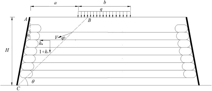
FIGURE 1. Analysis model of planar failure mode.
2.1.2 Derivation of work rates
2.1.2.1 Gravity work rate
The soil in zone ABC is regarded as a rigid-plastic body, and the area of the sliding wedge is
Because the admissible velocity field is translational, the velocity component along the gravity direction in the mechanism is equal to Vsin(θ−φ), then the work rate of the sliding wedge gravity is
where γ is the unit weight of the soil.
2.1.2.2 Work rate of seismic force
Considering the effect of horizontal and vertical seismic forces on the wedge, the corresponding work rates are, respectively
where G is the sliding wedge weight.
2.1.2.3 Surcharge work rate
The work rate of the surcharge on the embankment top surface can be expressed as
where lq is the distribution width of the strip surcharge on the sliding wedge.
2.1.2.4 Work rate related to lateral Earth pressure on the wrapped constraint ends
Since the surcharge distributes on a certain width, it only influences the lateral Earth pressure on the wrapped constraint ends at a limited height of the embankment. So, the expression of the Earth pressure in the ith layer can be divided into two cases.
Thus, the work rate corresponding to the lateral Earth pressure of the ith slice is
where K is the Earth pressure coefficient, and Hi is the vertical distance from the reinforcements’ layer to the embankment’s top surface.
Assuming that there are n layers of the reinforcements, then the total work rate related to the Earth pressure is
2.1.2.5 Dissipation power on the slip surface
According to the Mohr-Coulomb yield criterion and associated flow rule, the energy dissipation power on slip surface due to the friction is
where c is the cohesion of the filling soil.
2.1.2.6 Dissipation power of reinforcement failure
There are two possible failures for the reinforcements, including tensile cut-off and pull-out failure. For the former, Leschinsky and Reinschmidt (1985) believed that because the reinforcements are flexible materials and can only bear the tensile force, the reinforcement at the sliding surface can gradually adjust its position with the soil movement until it is in the same direction as the velocity V of the soil.
The energy dissipation power of the reinforcements in the sliding layer owing to tensile cut-off failure depends on generally two aspects. One is the power of reinforcement tensile force. The other is the power of friction between the reinforcement and soil. The frictional force can be regarded as a positive correlation with the small thickness of the sliding layer. It is assumed that the power of the friction is an ignored high-order small quantity compared with the power of the tensile force.
In the sliding layer, the tensile strain rate of the reinforcement
where ε is the axial strain of the reinforcement; Δl is the axial elongation of the reinforcement segment; t is the thickness of the sliding layer; l is the original length of the reinforcement in the sliding layer, and ΔT is a minimal time increment.
Thus, the energy dissipation power of the ith reinforcement can be expressed as
where T is the ultimate tensile strength per meter of the reinforcement.
For the pull-out failure of the ith layer reinforcement, it is necessary to overcome the sum of the reinforcement-soil friction in the sliding soil and the corresponding lateral Earth pressure on the wrapped constraint ends or that in the stable soil. Namely, the pulling force of the reinforcement for this failure mode should be adopted as
where FiL and FiR are the reinforcement-soil frictional resistance in the sliding soil and stable soil, respectively; and they can be expressed as
where c0 and φ0 are the cohesion and frictional angle of the reinforcement-soil interface, respectively; NiL and NiR are the normal force on the ith layer reinforcement in the slide and stable soil, respectively; LiL and LiR are the lengths of the ith layer reinforcement in the slide and stable soil, respectively, and there are
The upper and lower reinforcement-soil interfaces are velocity discontinuities for the ith layer reinforcement, and the corresponding velocity is Vcos (θ−φ). So, the pullout dissipation power of the reinforcement can be derived as
In the tensile failure state of the reinforcement, there is the minimum energy dissipation power between the tensile cut-off and pullout mode. Thus, the dissipation power of the ith reinforcement failure can be expressed as:
Naturally, the total energy dissipation power of n layers of reinforcement is
According to the upper-bound theory of plastic limit analysis (Chen, 1975), the total work rate of external forces is equal to the total dissipation power of internal energy. Namely, there is
Besides, it should be noted that the shear strength reduction approach can be introduced in the above analysis with the factor of safety Fs of the soil slope stability (Zienkiewicz et al., 1975). Namely, there is
where φ′ and c′ are the soil’s internal friction angle and cohesion after strength reduction, respectively.
Thus, by replacing φ and c with φ′ and c′ respectively in the previously related formulas and then substituting Eqs 2–5, 8, 9, 15 into Eq. 16, the relationship between the safety factor Fs and dip angle of the potential slip surface θ can be obtained. Therefore, the minimum Fs and the corresponding slip surface can be determined by
The computational procedure can be easily carried out via computer programs such as Microsoft Excel or Matlab.
2.2 Log-spiral failure mode
2.2.1 Analysis model
As shown in Figure 2, the potential sliding surface can be generally assumed as a curved plane. For simplification, a log-spiral slip surface is adopted herein, and its equation can be written as (Chen and Snitbhan, 1975)
where r is the distance from any point on the slip surface AC to its rotation center O, r0 and rh are the length of lines OA and OC, respectively; θ is the inclination angle between the radius of the slip surface AC and the horizontal direction, where subscripts 0, i, h stands for starting radius OA, the ith layer of reinforcements, and ending radius OC, respectively; Ω is the angular velocity of the sliding wedge rotating around point O; LAB is the distance between points A and B on the top of the reinforced embankment.
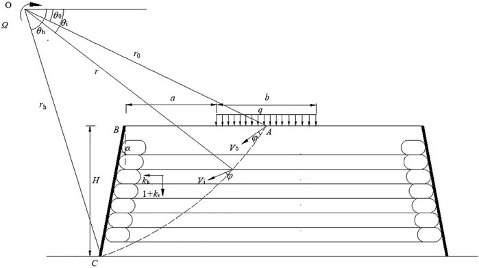
FIGURE 2. Analysis model of log-spiral failure mode.
The following geometric relationships can be obtained from Figure 2 as
2.2.2 Derivation of work rates
2.2.2.1 Gravity work rate
The sliding body ABC is equal to the area OAC minus areas OAB and OBC (see Figure 2). So, the gravity work rate of mass ABC can be obtained by superpositioning the corresponding work rates of the three areas.
The gravity work rate of zone OAC can be calculated by the integral method to be derived as
The gravity work rate of zones OAB and OBC can also be derived respectively as
Thus, the gravity work rate of slide mass ABC can be expressed as
where the calculation coefficients
2.2.2.2 Work rate of seismic force
Similar to the determination approach of the gravity work rate of mass ABC, the work rate of the corresponding vertical and horizontal seismic force can be derived, respectively as
where the calculation coefficients
2.2.2.3 Surcharge work rate
Considering three possible location relationships between the surcharge and slide mass ABC, the surcharge work rate Wq can be expressed as three cases as
where the calculation coefficients fi (i = 7 and 8) are
2.2.2.4 Work rate related to lateral Earth pressure on the wrapped constraint ends
According to the direction of the velocity at the intersection between the slip surface and each reinforcement layer, the work rate related to the lateral Earth pressure on the wrapped constraint end of the ith reinforcements can be derived as
Similarly, the total work rate related to the lateral Earth pressure can be written in the same format as Eq. 8.
2.2.2.5 Dissipation power on the slip surface
The energy dissipation power on the slip surface AC can be obtained by integral calculus as
where the calculation coefficient f9 is
2.2.2.6 Dissipation power of reinforcement failure
As shown in Figure 3, the axial strain rate of the linear segment of the ith reinforcement in the sliding layer can be expressed as
where Δθ is the increment of the inclination angle between the starting and ending radius corresponding to the linear segment of the ith reinforcement in the sliding layer.
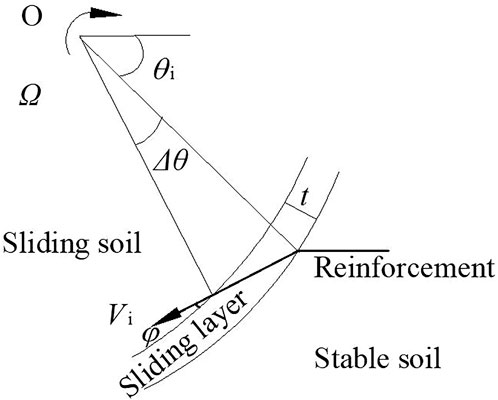
FIGURE 3. Movement mode of reinforcement in sliding layer under the log-spiral mode.
If the reinforcement is in the tensile cut-off state, the energy dissipation power of the ith layer can be expressed as
Based on the direction of the velocity at the intersection between the slip surface and the ith reinforcement, if the ith reinforcement is in the pulling-out state, the corresponding energy dissipation power can be derived as
where the two lengths LiL and LiR are respectively expressed as
Further, the expression of the pulling-out energy dissipation power of the ith reinforcement and the total dissipation power of all reinforcements are the same as Eqs 14, 15, respectively.
Similarly, the factor of safety of the soil slope stability can be introduced via Eq. 17, and the relationship between Fs and variables θ0 and θh can be determined via Eq. 16. Then the minimum safety factor and the corresponding slip surface can be obtained by
3 Practical example and verification
A geogrid-reinforced embankment on a stable foundation in a single-track railway in Bangladesh is shown in Figure 4. The width of the top surface of the embankment is 10.6 m, and there is an equivalent strip surcharge of 70 kPa with a 3.7 m distribution width in the middle of the top of the embankment with a 6 m height. The horizontal net distance between the surcharge and the slope crest is 3.45 m. The angle between the wall panel and the vertical direction is 3°, and the unit weight and internal friction angle of the sandy filling are 20 kN/m3 and 30°, respectively. The designed ultimate tensile force of the geogrids is 24 kN/m after the requirement of safety margin. According to the field seismic conditions, the horizontal and vertical seismic coefficients are specified as kh = 0.2 and kv = 0.1, respectively.
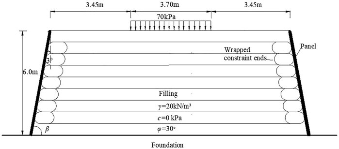
FIGURE 4. Cross-sectional diagram of a bilaterally wrapped geogrid-reinforced embankment.
The factors of safety of the reinforced embankment obtained using the proposed method are shown in Figure 5. As can be seen, the safety factor is nonlinearly decreasing with the increase of the reinforcement spacing. There are similar results between the planar mode and log-spiral failure mode. To verify the proposed method, numerical modeling via FLAC3D (Rai et al., 2012; Mabrouk et al., 2018) is established (see Figure 6) for the reinforced embankment. The elastic-perfectly plastic constitutive model, the Mohr-Coulomb yield criterion, and the associative flow rule are assumed to simulate the soils. The panels are simulated with the linear elastic model. The geogrids are modeled with the Geogrid Element inserted in FLAC3D, and the shear characteristics of the geogrid-soil interface obey the elastic-perfectly plastic mode. The left and right boundaries of the numerical model are fixed in the horizontal direction, while the bottom is fixed in both the horizontal and vertical directions. The hexahedral mesh is used to divide the entity model to form a total of 239,520 elements and 254,851 nodes. Equivalent seismic forces are exerted on each element based on the pseudo-static approach. The main physical and mechanical parameters involved in the numerical model are shown in Tables 1, 2, which is determined mainly according to the related laboratory material tests with enough number to eliminate possible accidental error, as well as the empirical references in FLAC3D.
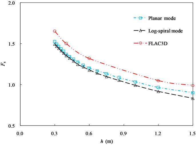
FIGURE 5. Calculation results of factor of safety using different methods.
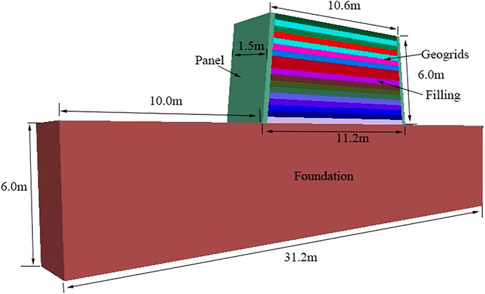
FIGURE 6. Numerical model via FLAC3D for the example.
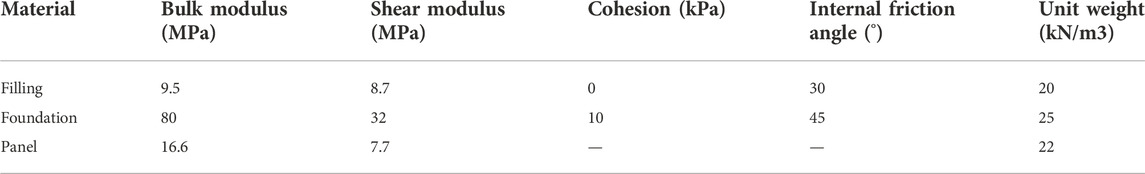
TABLE 1. Material properties of the numerical model.
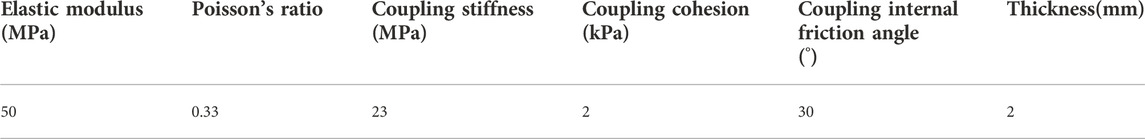
TABLE 2. Geogrid and geogrid-soil interface parameters.
It can also be seen from Figure 5 that the factors of safety by FLAC3D are slightly larger than the proposed results under different reinforcement spacing, and the relationships between Fs and h using the analytical and numerical methods are similar. If the geogrid spacing is 0.3 m, the factors of safety of using FLAC3D and the proposed method with planar mode and log-spiral mode are 1.66, 1.52, and 1.49, respectively, and the maximum relative error is 10.2%. So, the proposed results are in good agreement with the numerical value. According to Li et al. (2006), the safety factor of embankment stability should not be less than 1.3 in some cases. The maximum vertical spacing of the geogrids is accordingly figured out to be 0.46 m by the planner mode and 0.43 m by the log-spiral mode. So the latter can be conservatively adopted as the design control value. There are some differences of the calculation results between the two failure surface modes. The reason lies mainly that the shape of the slip surface has close influence on the internal and external power of the failure mechanism. In particular, the dissipation power of the log-spiral slip surface is more significant than that of the planar slip surface, which means the required reinforcement spacing under the former is possibly smaller than that under the latter. In addition, from the perspective of deformation mechanism of the reinforced embankment, the reinforcement tension in the planar mode is much more developed than that in the log-spiral mode, which naturally allows a higher reinforcement spacing to maintain the specified stability of the embankment.
The other geosynthetics-reinforced embankment with vertical slope face under different seismic actions is adopted herein to further verify the proposed method. The embankment height is 6 m and the reinforcement spacing is 0.6 m. The unit weight and internal friction angle of the sandy filling are 16 kN/m3 and 32°, respectively. The horizontal seismic coefficient is 0.25, and the reinforcement strength is 90 kN/m. The proposed results are shown in Figure 7, where they are compared with the results by FHWA (2009) and Xu and Hatami (2019). As can be seen, the proposed results are fairly close to those using the existing methods, particularly in most cases of −1 ≤ kv/kh ≤ 1. If kv/kh = 0.5, the proposed safety factors under the planer and log-spiral modes are individually 1.303 and 1.290, whose relative errors with those by FHWA (2009) and Xu and Hatami (2019) are 0.5% and 1.3%, 1.5% and 0.3%, respectively.
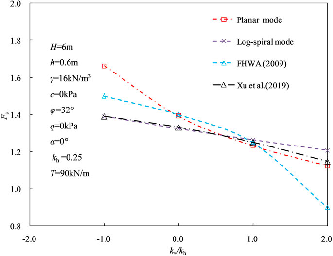
FIGURE 7. Comparison of factor of safety of another example using different methods.
4 Parameter study and discussion
According to the proposed analysis model and derived formulas, many factors have influences on the reinforcement spacing. The reinforced embankment shown in Figure 4 is taken herein as an example to discuss the influences by the essential parameters, including T, γ, c, φ, q, kh and kv. The parameter study is conducted using the controlling variable tactic with specified basic values c = 0 kPa, φ = 30°, γ = 18 kN/m3 α = 3°, a = 3.45 m, b = 3.7 m, H = 6 m, T = 24 kN/m, q = 70 kPa, kh = 0.2 and kv = 0.1. The values of each parameter are assumed mainly according to the common range in practical engineering as well as the related empirical data. Besides, vertical seismic coefficient is usually half of the horizontal seismic coefficient (Kavazanjian, 1995).
4.1 Reinforcement strength
The variation of the safety factor with the reinforcement spacing under different reinforcement strengths is shown in Figure 8. It can be seen that the nonlinear negative relationship between the factor of safety and the reinforcement spacing is noticeable under different T. Figure 9 shows that the spacing is nonlinearly increasing with the reinforcement strength under Fs = 1.0. However, the nonlinear characteristics are not obvious with the increase of Fs. Additionally, the spacing is almost not influenced as expected under a designed safety factor if the reinforcement strength reaches a relatively high value.
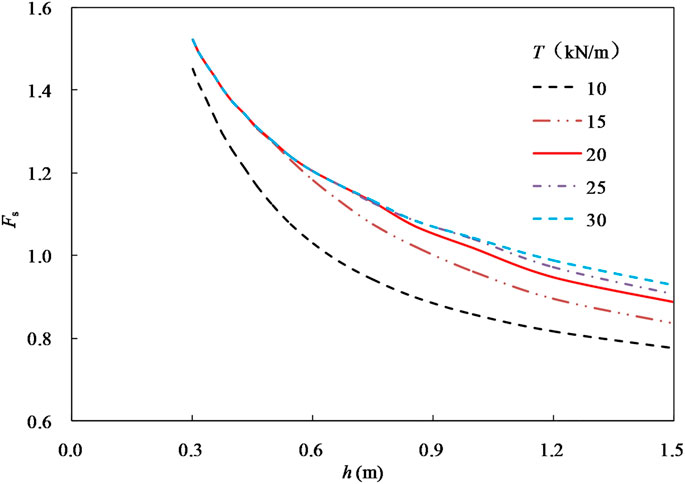
FIGURE 8. Relationship between Fs and h under different T.
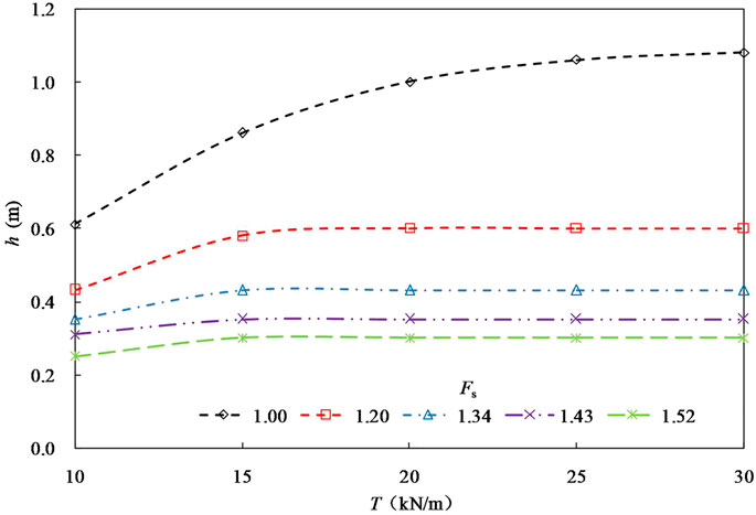
FIGURE 9. Relationship between h and T under different Fs.
4.2 Unit weight of filling
Figure 10 shows the relationship between the reinforcement spacing and the unit weight of the filling under different factors of safety. As can be seen, the unit weight has almost no effect on the reinforcement spacing. Under the same unit weight, the required spacing is nonlinearly decreasing with the safety factor increase. Taking the unit weight of 18 kN/m3 as an example, the reinforcement spacing required to meet the overall stability with designed safety factors of 1.20, 1.34, and 1.43 is 0.6, 0.43, and 0.38 m, respectively.
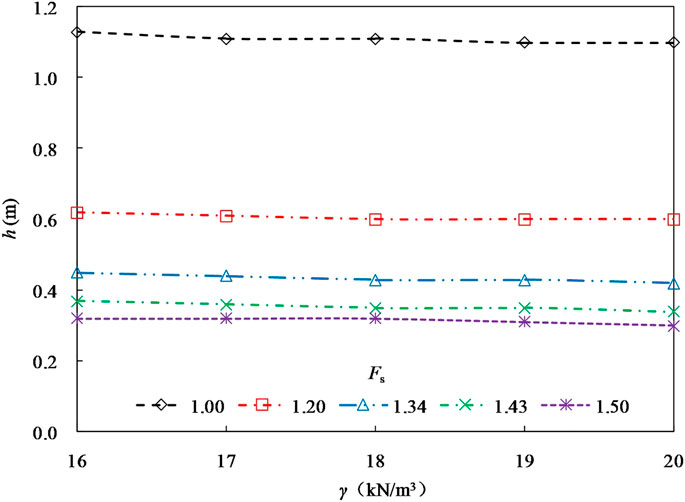
FIGURE 10. Relationship between h and γ under different Fs.
4.3 Cohesion of filling
The influence of the filling cohesion on the reinforcement spacing is shown in Figure 11. It can be seen that the spacing is generally nonlinearly increasing with cohesion. However, if the designed safety factor is small, there is an approximately linear relationship between the spacing and the cohesion, and the spacing necessary is considerably increasing with the cohesion. The filling shear strength is liable to meet the requirement of the overall stability of the reinforced embankment under lower factors of safety. In these cases, the effect of the reinforcements on the embankment stability is not significant to naturally allow fairly high reinforcement spacing.
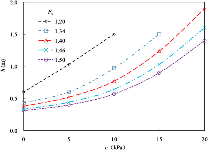
FIGURE 11. Relationship between h and c under different Fs.
4.4 Internal friction angle of filling
Figure 12 shows the relationship between the reinforcement spacing and the internal friction angle of the filling. As can be seen, with the increase of the internal friction angle, the reinforcement spacing required to meet the overall stability almost increases linearly. However, the increased gradient is closely related to the factor of safety. If the factor of safety is small and close to 1.0, the increasing gradient is relatively obvious; but if the factor of safety is high enough, the required spacing is almost not varied with the internal friction angle.
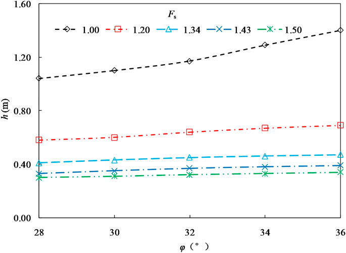
FIGURE 12. Relationship between h and φ under different Fs.
4.5 Strip surcharge
Figure 13 reveals the variation of the reinforcement spacing with the strip surcharge under different safety factors. As the strip surcharge increases, the reinforcement spacing is approximately linear decreasing. The decrease gradient depends to some extent on the specified factor of safety. With the increase of safety factor, the decrease gradient is reduced.
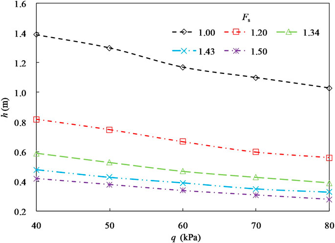
FIGURE 13. Relationship between h and q under different Fs.
4.6 Seismic coefficients
The relationships between the reinforcement spacing and the horizontal and vertical seismic coefficient under different safety factors are shown in Figure 14 and Figure 15, respectively. It can be seen from Figure 14 that the reinforcement spacing decreases nonlinearly with the increase of the horizontal seismic coefficient. As the specified factor of safety increases, the nonlinear characteristics lessen to some extent. Figure 15 reveals the spacing is almost linearly reducing as the vertical seismic coefficient increases. With the rise of the designed safety factor, the decrease gradient reduces gradually. Under high safety factors, the vertical seismic coefficient has a minor effect on the reinforcement spacing.
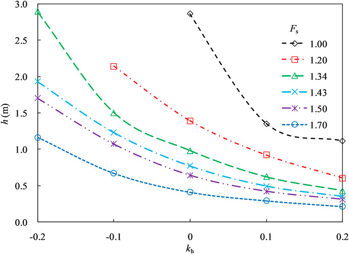
FIGURE 14. Relationship between h and kh under different Fs.
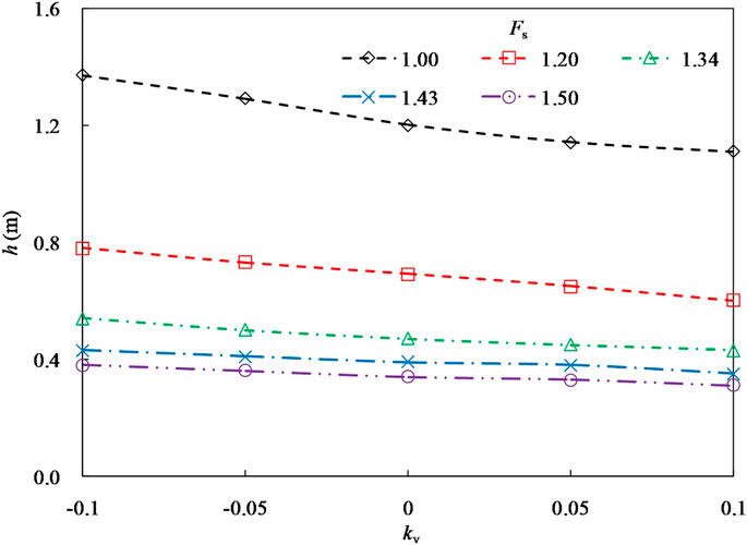
FIGURE 15. Relationship between h and kv under different Fs.
4.7 Sensitivity analysis
The sensitivity of the vertical spacing to the seven independent parameters mentioned-above can be further analyzed by an orthogonal test design. According to the empirical range of physical and mechanical indexes of embankment filling, four levels are assumed for this test, and the specific values are shown in Table 3. So, the total number of the orthogonal test can be assumed as 32 to effectively reflect the combination of different factors. The range analysis results of the orthogonal test are listed in Table 4, where K1, K2, K3 and K4 as well as m1, m2, m3 and m4 are the sum and arithmetic mean values of the corresponding test results if the level is 1, 2, 3 and 4, respectively; and R is the range of m. As can be seen that the range value of the seven factors T, γ, c, φ, q, kh and kv are 0.048, 0.056, 0.388, 0.086, 0.212, 0.653 and 0.126, respectively. Therefore, the sensitivity order of these factors from large to small is subsequentially horizontal seismic coefficient, filling cohesion, strip surcharge, vertical seismic coefficient, filling internal friction angle, filling unit weight, and reinforcement strength.
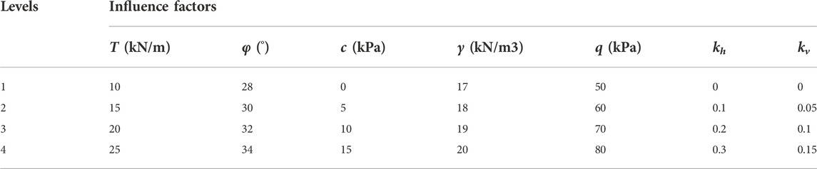
TABLE 3. Factors and levels of the orthogonal test.
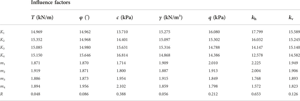
TABLE 4. Range analysis results of the orthogonal test.
5 Conclusion
Based on the upper-bound limit analysis method and pseudo-static approach, a stability analysis method of the bilaterally wrapped reinforced embankment under strip surcharge and seismic action is provided considering the planar and log-spiral failure mechanism of the reinforced embankment, which can substantially reflect the relationship between the reinforcement spacing and the overall stability of the reinforced embankment. Under a specified factor of safety of the overall stability, the required spacing can be consequently figured out. The main conclusions are drawn as follows:
• The safety factor of the reinforced embankment decreases nonlinearly with the increase of reinforcement spacing, and similar results are obtained in the planar and log-spiral failure mechanisms. Under the same safety factor for the stability requirement, the allowable reinforcement spacing calculated using the log-spiral mode is smaller and more conservative than that using the planar mode. Under a specified reinforcement spacing in some examples, the maximum relative error of the safety factor between the proposed method and some existing methods, including FLAC3D, is around 10%.
• The proposed method can quantitatively reflect the influence of properties of the filling, reinforcement strength, seismic forces, strip surcharge, and geometry of the embankment on the reinforcement spacing under a specified safety factor. The reinforcement spacing is nonlinearly positively related to the filling cohesion and approximately linearly positively related to the internal friction angle of the filling, while the unit weight of the filling does not almost influence it.
• The nonlinear negative relationship between the factor of safety and the reinforcement spacing is noticeable under different reinforcement strengths, but the nonlinear characteristics are not obvious with the increase of the design factor of safety. The spacing is scarcely influenced under a design factor of safety if the reinforcement strength reaches a relatively high value. The spacing is almost linearly reduced as the strip surcharge or vertical seismic coefficient increases, whereas it decreases nonlinearly with the rise of the horizontal seismic coefficient.
Data availability statement
The original contributions presented in the study are included in the article/Supplementary Material, further inquiries can be directed to the corresponding author.
Author contributions
QY: conceptualization, methodology, software analysis, data curation, writing- original draft preparation. SX: supervision, reviewing and editing.
Conflict of interest
The authors declare that the research was conducted in the absence of any commercial or financial relationships that could be construed as a potential conflict of interest.
Publisher’s note
All claims expressed in this article are solely those of the authors and do not necessarily represent those of their affiliated organizations, or those of the publisher, the editors and the reviewers. Any product that may be evaluated in this article, or claim that may be made by its manufacturer, is not guaranteed or endorsed by the publisher.
References
Abu-Farsakh, M. Y., Gu, J., Voyiadjis, G., and Tao, M. J. (2007). Numerical parametric study of strip footing on reinforced embankment soils. Transp. Res. Rec. 2004, 132–140. doi:10.3141/2004-14
Ahmadabadi, M., and Ghanbari, A. (2009). New procedure for active Earth pressure calculation in retaining walls with reinforced cohesive-frictional backfill. Geotext. Geomembranes 27, 456–463. doi:10.1016/j.geotexmem.2009.06.004
Basha, B. M., and Babu, G. L. S. (2011). Seismic reliability assessment of internal stability of reinforced soil walls using the pseudo-dynamic method. Geosynth. Int. 18, 221–241. doi:10.1680/gein.2011.18.5.221
Chen, H. T., Hung, W. Y., Chen, P. W., and Lee, C. J. (2015). Improvement of the stability of a vertical geotextile reinforced Earth wall backfilled with low strength clayey soil. Int. J. Phys. Model. Geotechnics 7, 35–45. doi:10.1680/ijpmg.2007.070203
Chen, J. F., Liu, J. X., Xue, J. F., and Shi, Z. M. (2014). Stability analyses of a reinforced soil wall on soft soils using strength reduction method. Eng. Geol. 177, 83–92. doi:10.1016/j.enggeo.2014.05.018
Chen, W. F. (1975). Limit analysis and soil plasticity. Amsterdam, Netherlands: Elsevier Scientific Publishing Company. doi:10.1016/b978-0-444-41249-2.x5001-x
Chen, W. F., and Snitbhan, N. (1975). On slip surface and slope stability analysis. Soils Found. 15, 41–49. doi:10.3208/sandf1972.15.3_41
Choudhury, D., Mandal, J. N., and Nimbalkar, S. S. (2006). Seismic stability of reinforced-soil wall by pseudo-dynamic method. Geosynth. Int. 13, 111–119. doi:10.1680/gein.2006.13.3.111
Farshidfar, N., Keshavarz, A., and Mirhosseini, S. M. (2020). Pseudo-static seismic analysis of reinforced soil slopes using the horizontal slice method. Arab. J. Geosci. 13, 1–14. doi:10.1007/s12517-020-5269-0
Fhwa, (2009). Mechanically stabilized earth walls and reinforced soil slopes design and construction guidelines. Washington, D C, USA: Federal Highway Administration.
Gebremariam, F., Tanyu, B. F., Guler, E., Urgessa, G. S., and Shen, P. (2021). Numerical investigation of reinforced soil structures with GRS-IBS design features. Geosynth. Int. 28, 1–50. doi:10.1680/jgein.20.00031
Hajiazizi, M., Bavali, M., and Fakhimi, A. (2018). Numerical and experimental study of the optimal location of concrete piles in a saturated sandy slope. Int. J. Civ. Eng. 16, 1293–1301. doi:10.1007/s40999-017-0155-1
Holtz, R. D. (2017). 46th terzaghi lecture: Geosynthetic reinforced soil: From the experimental to the familiar. J. Geotech. Geoenviron. Eng. 143, 03117001. doi:10.1061/(asce)gt.1943-5606.0001674
Kavazanjian, E. (1995). “Hanshin earthquake-replyCalifornia, CA, USA,” in NSF earthquake hazard mitigation program (Los Angeles: Geotechnical Bulletin Board).
Khoshzaban, A., Askari, F., and Farzaneh, O. (2021). Introduction of plastic block method in the upper bound limit analysis of soil stability problems. Int. J. Civ. Eng. 19, 897–910. doi:10.1007/s40999-020-00596-3
Lee, K. Z. Z., Chang, N. Y., and Ko, H. Y. (2010). Numerical simulation of geosynthetic-reinforced soil walls under seismic shaking. Geotext. Geomembranes 28, 317–334. doi:10.1016/j.geotexmem.2009.09.008
Leschinsky, D. (2007). Discussion of the influence of facing stiffness on the performance of two geosynthetic reinforced soil retaining walls. Can. Geotech. J. 44, 1479–1482. doi:10.1139/t07-100
Leschinsky, D., and Reinschmidt, A. J. (1985). Stability of membrane reinforced slopes. J. Geotech. Eng. 111, 1285–1300. doi:10.1061/(asce)0733-9410
Leschinsky, D., and Vulova, C. (2001). Numerical investigation of the effects of geosynthetic spacing on failure mechanisms in MSE block walls. Geosynth. Int. 8, 343–365. doi:10.1680/gein.8.0199
Li, X. H., Qin, L. X., Bao, L. M., Feng, J. D., and Wu, L. H. (2006). Code for design for applications of geosynthetics on subgrade of railway. Beijing, China: China Railway Publishing House.
Li, L. H., Cui, F. L., Ferreira, P., Xiao, H. L., and Jie, H. (2019). Experimental study of embankments with different reinforcement materials and spacing between layers. Geotext. Geomembranes 47, 477–482. doi:10.1016/j.geotexmem.2019.03.003
Li, Q., Ma, D., Zhang, Y. D., Liu, Y., and Ma, Y. J. (2021). Insights into controlling factors of pore structure and hydraulic properties of broken rock mass in a geothermal reservoir. Lithosphere-Us 5. doi:10.2113/2022/3887832
Ma, D., Duan, H. Y., Zhang, J. X., Liu, X. W., and Li, Z. H. (2022b). Numerical simulation of water–silt inrush hazard of fault rock: A three-phase flow model. Rock Mech. Rock Eng. 55, 5163–5182. doi:10.1007/s00603-022-02878-9
Ma, D., Duan, H. Y., and Zhang, J. X. (2022a). Solid grain migration on hydraulic properties of fault rocks in underground mining tunnel: Radial seepage experiments and verification of permeability prediction. Tunn. Undergr. Space Technol. 126, 104525. doi:10.1016/j.tust.2022.104525
Mabrouk, T., Ahmed, R., Mustapha, B., and Belkacem, A. (2018). Experimental and numerical analysis of geogrid-reinforced soil systems. Arab. J. Sci. Eng. 43, 5295–5303. doi:10.1007/s13369-018-3158-6
Michalowski, R. L. (1998). Limit analysis in stability calculations of reinforced soil structures. Geotext. Geomembranes 16, 311–331. doi:10.1016/s0266-1144(98)00015-6
Narasimha Reddy, G. V., Madhav, M. R., and Saibaba Reddy, E. (2008). Pseudo-static seismic analysis of reinforced soil wall-Effect of oblique displacement. Geotext. Geomembranes 26, 393–403. doi:10.1016/j.geotexmem.2008.02.002
Nouri, H., Fakher, A., and Jones, C. J. F. P. (2008). Evaluating the effects of the magnitude and amplification of pseudo-static acceleration on reinforced soil slopes and walls using the limit equilibrium horizontal slices method. Geotext. Geomembranes 26, 263–278. doi:10.1016/j.geotexmem.2007.09.002
Pain, A., Choudhury, D., and Bhattacharyya, S. K. (2017). Effect of dynamic soil properties and frequency content of harmonic excitation on the internal stability of reinforced soil retaining structure. Geotext. Geomembranes 45, 471–486. doi:10.1016/j.geotexmem.2017.07.003
Rai, R., Khandelwal, M., and Jaiswal, A. (2012). Application of geogrids in waste dump stability: A numerical modeling approach. Environ. Earth Sci. 65, 1459–1465. doi:10.1007/s12665-011-1385-1
Ren, F. F., Zhang, F., Xu, C., and Wang, G. (2016). Seismic evaluation of reinforced-soil segmental retaining walls. Geotext. Geomembranes 44, 604–614. doi:10.1016/j.geotexmem.2016.04.002
Romstad, K. M., Herrmann, L. R., and Shen, C. K. (1976). Integrated study of reinforced Earth–I: Theoretical formulation. J. Geotech. Engrg. Div. 102, 457–471. doi:10.1061/ajgeb6.0000269
Ruan, X. B., and Sun, S. L. (2013). Seismic stability of reinforced soil walls under bearing capacity failure by pseudo-dynamic method. J. Cent. South Univ. 20, 2593–2598. doi:10.1007/s11771-013-1773-7
Segrestin, P. “Design of sloped reinforced fill structure,” in Proceedings of the conference organized by the institution of civil engineers and robinson college, Cambridge, MA, USA, July 1992, 574–584.
Sitar, N., and Nova-Roessig, L. A. “Review of experimental studies of seismic behavior of reinforced soil structures,” in Proceedings of the Second International Conference On Earthquake Geotechnical Engineering, Rotterdam, Netherlands, June 1999, 1083–1088.
Tatsuoka, F. (2019). Geosynthetic-reinforced soil structures for railways and roads: Development from walls to bridges. Innov. Infrastruct. Solut. 4, 49. doi:10.1007/s41062-019-0236-x
Venkateswarlu, H., and Hegde, A. (2020). Isolation prospects of geosynthetics reinforced soil beds subjected to vibration loading: Experimental and analytical studies. Geotech. Geol. Eng. 38, 6447–6465. doi:10.1007/s10706-020-01447-7
Weerasekara, L., Hall, B., and Wijewickreme, D. (2017). A new approach for estimating internal stability of reinforced soil structures. Geosynth. Int. 24, 419–434. doi:10.1680/jgein.17.00012
Wu, J. T. H., and Pham, T. Q. (2013). Load-carrying capacity and required reinforcement strength of closely spaced soil-geosynthetic composites. J. Geotech. Geoenviron. Eng. 139, 1468–1476. doi:10.1061/(asce)gt.1943-5606.0000885
Xie, Y. G., and Leshchinsky, B. (2015). MSE walls as bridge abutments: Optimal reinforcement density. Geotext. Geomembranes 43, 128–138. doi:10.1016/j.geotexmem.2015.01.002
Xu, H., Ren, X., Chen, J. N., Liu, C. N., Xia, L., and Liu, Y. W. (2019). Centrifuge model tests of geogrid-reinforced slope supporting a high embankment. Geosynth. Int. 26, 629–640. doi:10.1680/jgein.19.00027
Xu, P., and Hatami, K. (2019). Sliding stability and lateral displacement analysis of reinforced soil retaining walls. Geotext. Geomembranes 47, 483–492. doi:10.1016/j.geotexmem.2019.03.004
Yang, X. L. (2007). Upper bound limit analysis of active earth pressure with different fracture surface and nonlinear yield criterion. Theor. Appl. Fract. Mech. 47, 46–56. doi:10.1016/j.tafmec.2006.10.003
Zheng, Y. W., and Fox, P. J. (2016). Numerical investigation of geosynthetic-reinforced soil bridge abutments under static loading. J. Geotech. Geoenviron. Eng. 142, 04016004. doi:10.1061/(asce)gt.1943-5606.0001452
Zhussupbekov, A. Z., Tanaka, T., and Aldungarova, A. K. (2015). Model tests of the influence of reinforcement on levee stability. Soil Mech. Found. Eng. 52, 131–134. doi:10.1007/s11204-015-9318-8
Zienkiewicz, O. C., Humpheson, C., and Lewis, R. W. (1975). Associated and non-associated visco-plasticity and plasticity in soil mechanics. Geotechnique 25, 671–689. doi:10.1680/geot.1975.25.4.671
Zornberg, J. G., Sitar, N., and Mitchel, J. K. (1998). Performance of geosyn-thetic reinforced slopes at failure. J. Geotech. Geoenviron. Eng. 124, 670–683. doi:10.1061/(asce)1090-0241(1998)124:8(670)
Keywords: geosynthetic-reinforced embankment, reinforcement spacing, upper bound limit analysis method, factor of safety, seismic forces
Citation: Yan Q and Xiao S (2023) Calculation method for reinforcement spacing of bilaterally wrapped reinforced embankments under seismic force. Front. Earth Sci. 10:1054595. doi: 10.3389/feart.2022.1054595
Received: 27 September 2022; Accepted: 17 November 2022;
Published: 19 January 2023.
Edited by:
Chengyi Pu, Central University of Finance and Economics, ChinaReviewed by:
Yankun Wang, Yangtze University, ChinaDan Ma, China University of Mining and Technology, China
Copyright © 2023 Yan and Xiao. This is an open-access article distributed under the terms of the Creative Commons Attribution License (CC BY). The use, distribution or reproduction in other forums is permitted, provided the original author(s) and the copyright owner(s) are credited and that the original publication in this journal is cited, in accordance with accepted academic practice. No use, distribution or reproduction is permitted which does not comply with these terms.
*Correspondence: Shiguo Xiao, eGlhb3NoaWd1bzE2M0AxNjMuY29t