- 1School of Civil Engineering, Liaoning Technical University, Fuxin, China
- 2Liaoning Key Laboratory of Mine Subsidence Disaster Prevention and Control, Fuxin, China
Existing studies on surface deformation prediction consider single soil layers and straight-line excavation when investigating deformation caused by metro shield construction. In this study, we provide a new prediction method for studying the soil deformation caused by curved shield tunnel construction in the upper soft and lower hard soil. The deformation equations are derived using the Mindlin solution and random medium theory and are verified using engineering examples and numerical simulation. The influencing factors and laws of the surface deformation caused by the excavation are also identified. The study found that the horizontal settlement trough on the ground surface was distributed asymmetrically during the curve construction, with maximum settlement on the inner side of the curve. The offset and settlement values were affected by the thrust difference coefficients α and β and the turning radius. When constructing in the upper soft and lower hard soil layers, the settlement trough tends to become wider and shallower. The results show that the derived equation is suitable for actual engineering calculations, and the measured data are in good agreement.
Introduction
With the rapid development of urban rail transportation, shield construction has become the main method of subway tunnel construction because of its high efficiency and low impact on the surrounding environment. However, owing to the unpredictability of construction, accurate prediction of surface deformation is crucial for safe shield construction. Many scholars have studied the surface deformation prediction caused by metro shield construction using methods such as empirical methods (Peck, 1969; Fargnoli et al., 2013; Broere and Festa, 2017), theoretical analysis methods (Sagaseta, 1987; Yuan et al., 2018; Zhang M. et al., 2020), numerical simulation methods (Sugimoto et al., 2007; Gong et al., 2020), and model test methods (Xie et al., 2012; Zhang et al., 2018; Lei et al., 2021).
However, the abovementioned methods are mainly used to study the surface deformation caused by a linear shield construction under the condition of single-layer or multi-layer soil with similar mechanical indexes transformed into a single uniform soil layer using the weighted average method, and shield construction is often limited by complex soil layer conditions and tunnel route planning. When the shield machine is in a soil layer that has large differences in mechanical indexes, the influence of curve construction on surface deformation is very different from that of straight-line shield construction under the condition of a single soil layer (Katebi et al., 2015). Zhang et al. (2011) studied the ground surface changes caused by tunneling in multi-layer soil, considered the influence of soil stratification, and predicted the ground surface deformation using the displacement control boundary integral method. Li et al. (2018) studied the stability of the working face during tunnel shield excavation in multi-layer soil and developed a calculation method for the ultimate support pressure of the excavation face in multi-layer soil. Likitlersuang et al. (2014) and Likitlersuang et al. (2019) studied the surface subsidence caused by soil loss during tunnel excavation in multi-layered soil and determined the range of tunnel shrinkage rates under different conditions. Based on the elastic equivalence theory, Cao et al. (2020) converted the excavation and convergent boundaries of a shield tunnel from a multi-layer soil system to a single-layer soil system, and the calculation accuracy was significantly improved. Li et al. (2021) studied the variation law of the additional stress caused by a shield curve construction load and deduced the analytical equation for the additional stress of a curve shield. Wu et al. (2021) used the nonlinear three-dimensional finite element method to study the characteristics and laws of the surface deformation caused by a double-track shield along the curve. Zhang Z. et al. (2020) studied the influence of the yaw excavation load on the surface displacement and segment stress of a curved shield tunnel using a finite element model. Li et al. (2021) deduced the analytical solution of additional stress caused by construction load of a curved shield tunnel based on three-dimensional imaging theory. Wu et al. (2021) investigated the ground deformation characteristics induced by mechanized shield twin tunneling along curved alignments by adopting the nonlinear three-dimensional finite element method. Deng et al. (2022) derived the prediction equation for surface settlement in curved shield construction and studied the influence of the unbalanced force difference coefficient and curve radius on the surface deformation. Zhang W. et al. (2021) and Zhang W. et al. (2022) predicted the surface deformation caused by tunnel excavation in multi-layer soil using machine learning and a neural network. However, the abovementioned studies only considered the impact of multi-layer soil or shield curve construction on tunnel construction and surface deformation; however, these two factors were not considered comprehensively, and less consideration was given to upper soft and lower hard soil conditions with large differences in mechanical parameters. In this article, the equation of the surface deformation caused by the curved construction of the shield machine in the upper soft and lower hard soil layers is derived, the influencing factors and laws of the surface deformation are studied, and the effectiveness of this method is verified using an engineering example.
Calculation Model and Assumptions
Mechanical Model of Shield Tunneling
The disturbance forces in the surrounding soil during the curved shield construction can be divided into three types: the uneven thrust force q at the excavation surface of the shield, the friction force f between the shield shell and surrounding soil, and the grouting pressure p at the end of the shield. Based on the characteristics of the three forces, a shield excavation mechanics model is established, where the excavation direction of the shield machine is in the positive direction of the x-axis, and the excavation surface is located in the yoz plane at x = 0.
For convenience, subsequent calculations satisfy the following assumptions:
1) The soil has two layers with different elastic parameters, where the thickness of the upper layer is H1, and the lower layer is an elastic semi-infinite space. Both the upper and lower layers are undrained.
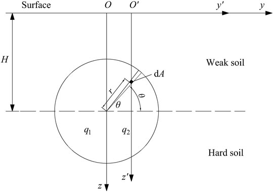
2) When the curve shield is constructed, an uneven thrust q acts on the excavation surface; the thrust q1 on the inside of the curve is smaller than the thrust q2 on the outside. If the centerline of the shield cutter is used as the boundary, then q2 = αq1, α is greater than 1 and is the coefficient of difference between the thrusts on both sides.
3) When tunneling in the curved section with the midline of the shield blade as the boundary, the larger extrusion of the inner shell of the surrounding soil results in the friction force f1 on the inner side of the curve becoming larger than the friction force f2 on the outer side., i.e., f2 = βf1, β is smaller than 1 and is the friction force difference coefficient on both sides.
4) The influence range of the grouting pressure at the end of the shield is mainly the width of the tube sheet in the back ring of the shield tail and is uniformly distributed radially along the circumference of the tube sheet.
Soil Layer Conversion
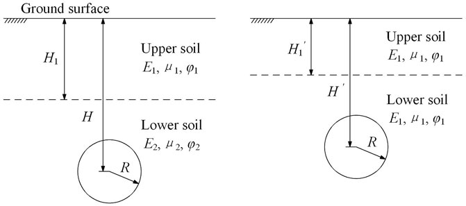
Because the Mindlin solution is used in an isotropic linear elastic semi-infinite space, when dealing with complex soil conditions, the weighted average method can be used to simplify different soil layers with approximate mechanical parameters into a single uniform soil layer, Subsequently, for calculations, the layer method is used to convert the upper soft and lower hard soil layers with a large difference in mechanical parameters into a uniform soil layer with unified parameters (Zhou et al., 2020). The soil transformation model is shown in Figure 1, the upper soil layer thickness is H1, and the elastic modulus, Poisson’s ratio, and internal friction angle are E1, μ1, and φ1, respectively. The modulus of elasticity, Poisson’s ratio, and angle of internal friction of the soil layer below are E2, μ2, and φ2, respectively. The buried depth of the shield axis is H, and the shield radius is R. After transformation, the mechanical parameters of the upper soil layer with thickness H1′ become E2, μ2, and φ2. The buried depth of the shield axis is H’.
The height of the upper layer of soil after conversion is
When the mechanical parameters of the upper and lower soil layers differ greatly, a = 0.33, and when the mechanical parameters of the upper and lower soil layers have a small difference, a = 0.5. Assuming that the coordinates of any point in the current soil layer are (x, y, z), a new coordinate system (x′, y′, z′) after transformation of the upper soft and lower hard soil layers is established, where
Surface Deformation Caused by Shield Construction
Uneven Thrust
Mindlin (1936) derived a point (0, 0, c) in a semi-infinite elastic space (x′, y′, z′) under the action of the vertical concentrated force Pv and horizontal concentrated force Ph. The vertical displacements wv and wh are obtained using Eqs 3, 4, respectively.
where G is the soil shear modulus (kPa) and μ is Poisson’s ratio.
The soil deformation calculation model obtained by the additional thrust on the excavation surface when the shield machine is driving in the curved section of the upper soft and lower hard soil layer is shown in Figure 2. The additional thrust q is assumed to be unevenly distributed at the cut, and the inner and outer thrusts of the curve are q1 and q2, respectively; this is shown by the division of the tunneling soil layer into upper and lower layers.In the area dA = rdrdθ of any micro-element in the excavation surface, r is the distance from the micro-element to the center of the excavation surface, and θ is the angle between the micro-element and the center horizontal plane of the excavation surface.
Based on the coordinate transformation, the general analytical Mindlin equation at any point in the space coordinates can be derived. We assume that the space coordinate xyz is parallel to the corresponding coordinate axes of the local coordinate x′y′z′. The distances from the coordinate origin of the offset space coordinate system xyz are l, m, and n, respectively, and the following relationship holds:
Substituting Eq. 6 into Eqs 3–5, the vertical displacement at any point (x, y, z) in the space coordinates of the actual soil mass can be obtained. Substituting l = 0, m = rcosθ, and n = 0 into Eq. 4, and calculating for the uneven thrust on both sides of the shield curve tunneling construction, we obtain
where α is the thrust difference coefficient and
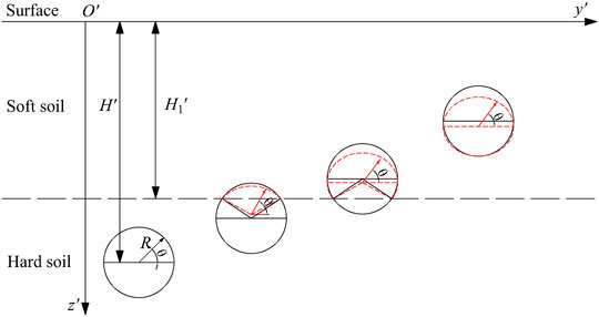
The soil conditions that the shield machine may encounter during the actual construction process, as shown in Figure 3, can be divided into the following four situations: 1) the shield machine in the hard soil layer, 2) most of the shield machine in the hard soil layer, 3) most of the shield machines in the soft soil layer, and 4) shield machines in the soft soil layer. The cross-sectional area of the weak soil layer, marked by the red dashed line, is determined by the ellipse and soil layer boundaries, and the integration area of the hard soil layer, marked by the black solid line, is determined by the original circle and soil layer boundaries.
In addition, owing to the different positions of the soil layer in the tunnel section, the calculation parameter c in Eq. 7 can be expressed as a geometric relationship as follows:
1) When the shield tunnels are in the lower soil layer, substituting Eqs. 6, 8, and 9 into Eq. 7, the vertical displacement of the soil layer caused by the unbalanced force at the excavation surface can be obtained as
2) When most sections of the shield tunnel are in the lower soil, the integral boundary cannot be expressed uniformly and is divided into three areas: the upper ellipse, lower part of the circle, and lower triangle, as shown in Figure 4.
1) Upper ellipse area integral, wqt:
The upper and lower limits of θ are
The upper and lower limits of r′ are
Substituting Eqs. 6, 8, 9, 11, and 12 into Eq. 7, we derive
2) Area integral wqy of the lower part of the circle:
The upper and lower limits of θ are
Substituting Eqs. 7, 9, 10, and 14 into Eq. 7, we obtain
3) Area integral wqs of the lower triangle:
The upper and lower limits of θ are
The upper and lower limits of r′ are
Substituting Eqs. 6, 8, 9, 16, and 17 into Eq. 7, we derive
The total vertical displacement is
3) Most sections of the shield tunnel were in the upper soil.
1) Upper ellipse area integral, wqt:
The upper and lower limits of θ are
The upper and lower limits of r′ are
Substituting Eqs. 6, 8, 9, 20, and 21 into Eq. 7, we derive
2) Area integral wqy of the lower part of the circle:
The upper and lower limits of θ are
The upper and lower limits of r′ are
Substituting Eqs. 6, 8, 9, 23, and 24 into Eq. 7, we derive
3) Integral wqs of the lower part of the triangular area:
The upper and lower limits of the θ are
The upper and lower limits of r′ are
Substituting Eqs. 6, 8, 9, 26, and 27 into Eq. 7, we derive
4) When the shield tunnels are in the upper soil, the upper and lower integral limits of r are
Substituting Eqs. 6, 8, 9, and 29 into Eq. 7, we derive
Uneven Friction of Shield Shell
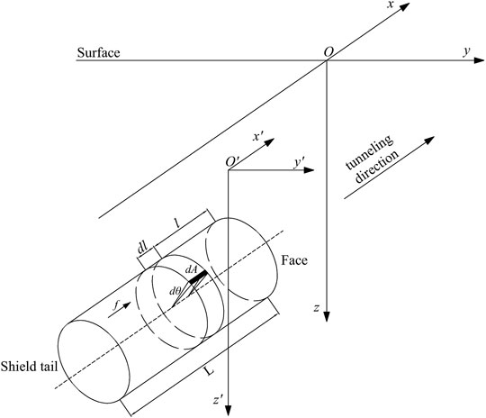
The calculation model of the ground uplift caused by the friction f between the shield shell and surrounding soil is shown in Figure 4. The calculation model can be regarded as the horizontal load acting along the cylinder axis on the side surface of the cylinder. The friction force f is assumed to be unevenly distributed along the central axis. For f1 and f2, the tunneling soil layer is divided into upper and lower layers. The inner and outer thrusts of the curve are q1 and q2, respectively. Suppose the length of the shield from the excavation cutter head to the tail of the shield is L. Then, the area of any infinite element on the surface of the shell is given by dA = Rdθdl, where l is the axial distance from the infinite element to the excavation surface, and the concentrated force received is dPh = fR′dθdl. We substitute l = −l, m = R′cosθ, and n = 0 in Eq. 6 to transform the coordinate system as follows.
Because of the unequal frictional resistance of the inner and outer shells of the curved shield tunnel and the integral between the partitions, the vertical displacement of the soil layer caused by the frictional distribution force of the infinitesimal element can be obtained from Eq. 4 as follows:
where β is the thrust difference coefficient and
Because there is no need to integrate in the triangular area, the second and third cases shown in Figure 3 can be regarded as the same. Therefore, the integration cases were as follows: 1) the full section of the tunnel is located in the lower soil; 2) the tunnel section spans the upper and lower layers; and 3) the full section of the tunnel is located in the upper soil. Because of the different positions of the soil layer in the section, the calculation parameters R and c in Eq. 31 are different. According to the geometric relationship, it can be expressed as follows:
1) When the full section of the tunnel is in the lower layer of soil, substituting Eqs. 6, 32, and 33 into Eq. 31, the vertical displacement of the soil layer caused by friction can be obtained as follows:
2) When the tunnel section crosses the upper and lower layers of soil, substituting Eqs 6, 32, 33 into Eq. 31, the integral boundary cannot be expressed uniformly; therefore, it is divided into an upper ellipse and a lower partial circle, and the two areas are calculated separately.
1) Upper ellipse area integral wft:
The upper and lower integral limits of θ are
Substituting Eqs. 6, 32, 33, and 35 into Eq. 31, we derive
2) Area integral of the lower part of the circle wfy:
The upper and lower integral limits of θ are
Substituting Eqs. 6, 32, 33, and 37 into Eq. 31, we derive
The total vertical displacement is
3) When the full section of the tunnel is in the upper soil, substituting Eqs. 6, 32, and 33 into Eq. 31, we derive
Shield Tail Grouting Pressure
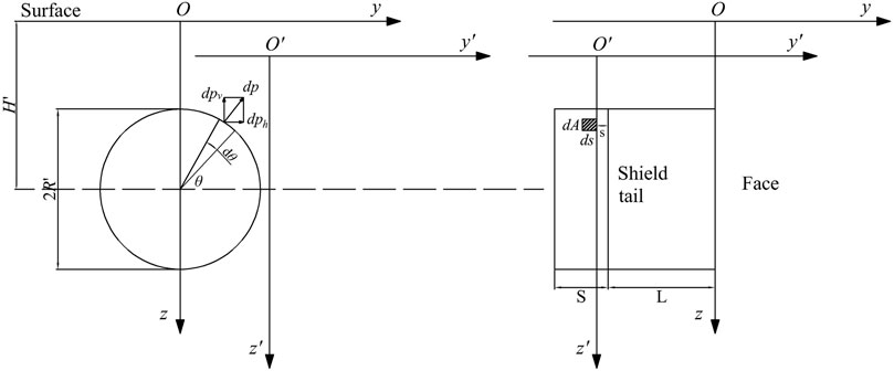
As shown in Figure 5, the length of the shield from the shield tail to the grouting end is s, and the grouting pressure at the shield tail is p. The grouting pressure decreases along the grouting length, reaching 0 at point S, far from the shield tail. For any infinite element dA = Rdθds, the concentrated force dp can be decomposed into the horizontal and vertical components dph and dpv, respectively. This paper only considers the ground displacement caused by the vertical component of the force, dph = p(1 − s/S)·Rdθds. In this section, we do not consider the influence of curved shield tunneling on the grouting pressure. Therefore, we set l = −L−s, m = Rcosθ, and n = 0, and substitute these in Eq. 6 to transform the coordinate system as follows:
From Eq. 2, the vertical displacement of the soil layer caused by the vertical component of the additional pressure of the synchronous grouting of the micro-element shield tail is obtained as
where S is the length of the grouting section of the shield tail (m). Generally, the width of a ring segment is 1.2 m.
Considering similar cases as in Section 3.2, we derive the following:
1) When the full section of the tunnel is in the lower soil, substituting Eqs. 6, 32, and 42 into Eq. 41, the vertical displacement of the soil layer caused by the shield tail grouting pressure can be obtained as
2) When the tunnel section crosses the upper and lower layers of soil, and substitutes Eqs. 6,32, and 42 into Eq. 41, the integral boundary cannot be expressed uniformly; therefore, it is divided into an upper ellipse and a lower partial circle, and the two areas are calculated separately.
1) Upper ellipse area integral wpt:
The upper and lower integral limits of θ are
Substituting Eqs. 6, 32, 42, and 44 into Eq. 41, we derive
2) Area integral of the lower part of the circle wpy:
The upper and lower integral limits of θ are
Substituting Eqs. 6, 32, 42, and 46 into Eq. 41, we derive
The total vertical displacement is
3) When the full section of the tunnel is in the upper soil, substituting Eqs. 6, 32, and 42 into Eq. 41, we derive
Soil Loss
During shield tunneling, over-excavation of the cutter head creates a gap between the shield shell and the surrounding soil, resulting in the loss, loosening, and deformation of the soil layer (Zou and Zuo, 2017). When calculating the surface deformation caused by the loss of the soil layer, as the curved shield will over-excavate the inner soil, the influence of the over-excavated part on the excavation boundary needs to be considered. When the upper soft and lower hard soil layers are equivalent to a single soil layer, the excavation and convergence boundary will change after convergence, that is, from a circle to a combination of an ellipse at the top and a circle at the bottom (Cao et al., 2020), as shown in Figure 6. The length of the semi-horizontal axis of the ellipse is the same as the radius of the original circle, the length of the semi-longitudinal axis is

FIGURE 6. Transformation model between excavation boundary and convergence boundary of curved shield.
For curved shields, owing to the large over-excavation on the inner side of the curved shield tunneling route, the equivalent soil loss parameter g on the inner side is larger than that on the outer side. The extra over-excavation amount on the inner side of the line is set as
According to Sun et al. (2019), the over-excavation amount on the inner side of the line in the curve shield construction is
where Rc is the curve radius of the curved shield tunnel and L is the length of the single-section shield shell. If the shield machine is equipped with a hinge device, L is half the length of the single-section shield shell.
The changes in the excavation boundary and convergence boundary are calculated using the random medium theory method. The influence of tunnel excavation on the ground surface can be regarded as the sum of the influences of an infinite number of unit excavation
where
where k is the width parameter of the ground settlement trough. According to Han and Li (2007),
According to Cao et al. (2019), the value of β in Eq. 53 varies with the location of the tunnel and can be divided into the following two cases:
1) When the tunnel axis is located in the upper soil, i.e., when H ≤ H1, there is
2) When the tunnel is located in the lower soil, i.e., when H > H1, there is
Equation 52 can only calculate the final stable settlement under the plane strain state and cannot calculate the three-dimensional settlement caused by soil loss. Cao et al. (2020) extended Eq. 52 to a three-dimensional state to determine the change in soil loss along the tunnel excavation direction as follows:
Then, the vertical displacement of the soil layer can be obtained by the integral method, as follows:
According to Figure 6, when the excavation surface is located in the upper soft and lower hard soil layers, Eq. 57 can be transformed into the following equation:
where
According to the ellipse equation, the upper and lower limits of the integral can be expressed by
Engineering Case Analysis
Relying on the example of the shield tunnel project of the intercity Pazhou branch line in the Pearl River Delta, the revised theoretical formula was used to analyze the construction influences of the shield machine in the upper soft and lower hard soil layers. Accordingly, the surface deformation caused by the shield tunnel excavation was solved, and the settlement value calculated using the revised formula was compared with the field measured value. The numerical simulation and theoretical formula values were compared to verify the validity and reliability of the calculation method deduced in this study.
Project Overview and Parameter Values
The total length of the shield tunnel was 3,257.36 m. The excavation diameter of the shield is 9.14 m, the length is 7.1 m, the outer diameter of the segment is 8.8 m, the inner diameter is 8.0 m, the ring width is 1.8 m, and the thickness is 0.4 m. The cover of the shield tunnel is 2.98–34.45 m. The maximum slope of the interval tunnel is 3%, and the minimum curve radius is 800 m. The crossing soil layers are mainly mixed soil layers of silty clay and fully weathered granite and are a mix of fully weathered, strongly weathered, and moderately weathered granite soil layers. The average pressure of the shield soil bin is maintained at 240–300 kPa, which is slightly higher than the static soil pressure at the center of the tunnel. Because the soil layer before the excavation slightly swells, a shield is used to compensate for the soil loss caused by the shield tail falling out. According to existing research (Sun et al., 2019; Deng et al., 2022) and engineering experience, the additional thrust on the inner side of the excavation surface is 60 kPa, the difference coefficient
Numerical Model
To verify the accuracy of the calculation results of the prediction equation (Likitlersuang et al., 2019; Petchkaew et al., 2022), the construction process of the shield machine curve tunneling in the upper soft and lower hard strata is simulated using the Midas GTS finite element software. The dimensions of the model are taken as 60, 100, and 40 m along the X, Y, and Z directions, respectively. The boundary conditions of the model are set to default. The bottom surface is fully constrained, the top surface is free, and normal constraints are applied on four sides. The numerical calculation model is shown in Figure 8.
The constitutive model of the rock and soil mass adopts the Mohr column model. The main structure adopted the elastic model, and the physical and mechanical parameters of the rock, soil mass, and main structural materials are listed in Table 1 γ, E, μ, φ, e, and c are the characteristic values of gravity, elastic modulus, Poisson’s ratio, internal friction angle, porosity, and cohesion, respectively.
Analysis of Results
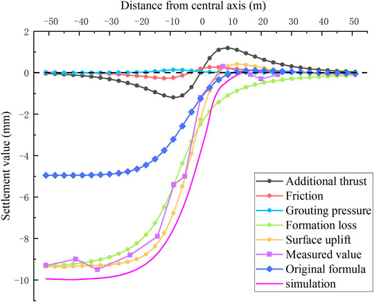
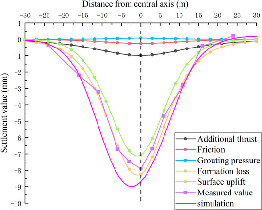
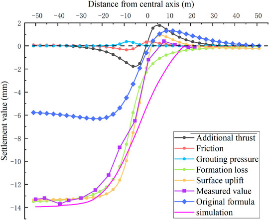
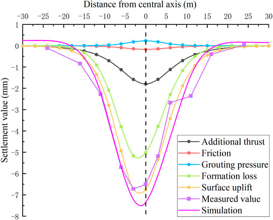
The surface deformations of Sections 1, 2 are calculated using the revised theoretical formula. The calculated results are compared with the measured, numerical simulation, and (original) theoretical formula values, as shown in Figures 9–12. The soil layer conditions and tunnel burial depth of Sections 1, 2 are shown in Figure 7, and the equivalent soil loss parameters are equal to 9.5 and 9.7 mm, respectively.
Figures 9, 11 shows that the longitudinal deformations of the surfaces of Sections 1, 2 are consistent. The longitudinal deformation of the surface caused by the additional thrust during shield construction is antisymmetrically distributed at the excavation face, and the maximum uplift value appears in front of the excavation face. At distances in the range of 5–10 m, the surface deformation caused by the frictional force of the shield shell reaches its maximum value along the rear of the excavation face at 0.5 L, it is uplifted in front of it, and subsidence is formed behind it. The grouting pressure of the shield tail caused the surface uplift. Moreover, the maximum uplift value appeared at 1 L behind the excavation face, that is, at the position at which the segment came out of the shield shell. The total surface deformation exhibited a rapid subsidence stage (5 m in front of the cutterhead to 25 m behind the cutterhead), and the uplift was larger within the range of 5–15 m in front of the cutterhead. At distances >25 m, the deformation was stable behind the cutterhead.
For analysis the lateral deformation of the surface of Section 1 at which the excavation surface is located (x = −14.2 m) and the lateral deformation of Section 2 at which the excavation surface is located (x = −5.1 m) were selected for analysis (Figures 10, 12). The lateral deformation laws of the surfaces of the two sections were the same. Due to the difference in friction between the two sides of the shield shell, the uneven additional thrust on the excavation surface, and the over-excavation inside the shield turning line, the soil loss inside the turning was large and led to the formation of the surface settlement tank. The lateral deformation of the total surface presents a specific asymmetry. However, owing to the high proportion of weak soil in Section 2, the peak value of the surface deformation curve was large.
Figures 9–12 show that the lateral and longitudinal deformations of Sections 1, 2 calculated by the modified theoretical formula are in good agreement with the measured deformation values, and the variation trend of the surface soil before and after excavation is consistent. In addition, the deformation curve of the simulation results obeys the same law as that obeyed by the measured results. This curve can also represent more accurately the process responsible for the changes in the surface deformation (which increases slowly and then falls rapidly) in front of the excavation. However, compared with the revised theoretical formula and the measured results, the numerical simulation showed that the surface settlement value behind the excavation face was larger, and the increase of the soil mass in front of the excavation face was smaller. This is mainly attributed to the fact that the numerical simulations do not consider the friction between the shield shell and the soil during excavation, or the influence of the shield shell side on the surrounding soil during shield turning.
The deformation curve of the original theoretical formula has values that are smaller than the measured results, and the calculated lateral settlement curve is centrosymmetric and has values that are different from the measured result. This is because the original theoretical formula did not consider the influences of the upper soft soil and the lower hard soil layers on the construction parameters, or the offset, or the increase in the settlement tank caused by the over-excavation of the shield machine inside the curve during tunnel construction.
In summary, the calculation method in this study can more accurately represent the surface deformation caused by the curved construction of the shield machine in the upper soft and lower hard soil layers. In conclusion, all construction parameters are affected by the changes in different soil layers and the construction process. Collectively, these parameters can provide a theoretical basis for the curved shield construction in the upper soft and lower hard soil layers.
Analysis of Influencing Factors
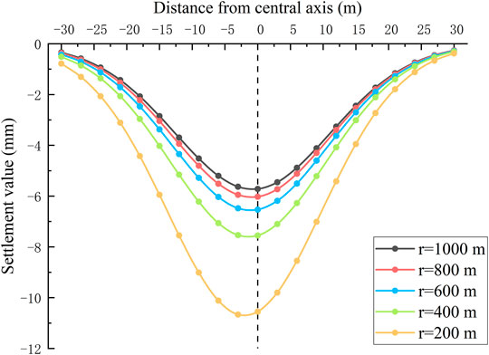
The following parameter values are used for calculating the influence of surface deformation on the soil layer: shield radius R = 4 m, shield buried depth H = 20 m, shield length L = 7 m, segment width = 1.2 m, soft soil elastic modulus E1 = 10 MPa, Poisson’s ratio μ1 = 0.35, hard soil elastic modulus E2 = 30 MPa, Poisson’s ratio μ2 = 0.25, additional thrust of the excavation surface = 50 kPa, friction force = 20 kPa, shield tail grouting pressure = 30 kPa, and soil loss rate Vloss = 0.4%; the width coefficient of the settlement tank k = 0.6, and construction gap g = 20 mm. For analysis, we choose a point at the tail of the shield on the surface axis and calculate the change rule of the uplift value at this point caused by each fixed construction parameter for different shield vault depth and excavation surface distance. A positive uplift indicates surface uplift, while a negative uplift indicates surface subsidence.
Influence of Different Turning Radii
When the shield is changed from straight excavation to curved excavation, as shown in Figure 2, the shield will apply an uneven additional thrust on the excavation surface. As the radius of the curve increases, the difference coefficient α increases accordingly. Differences in the friction between the inner and outer sides of the shield shell and the soil are observed during curve shield excavation. As the radius of the curve increases, the difference coefficient
Influence of Different Soil Conditions
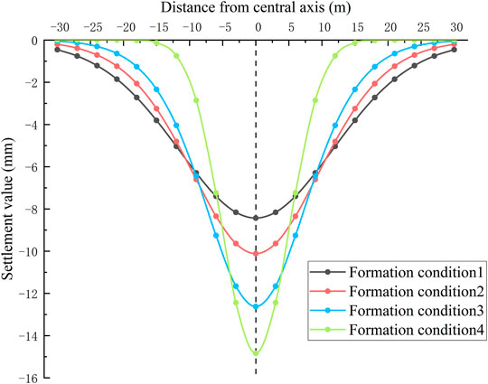
For comparing the uplift characteristics of the ground surface when the shield is driven in a straight line under different soil conditions, we assume that the buried depth of the tunnel is 4D. Four soil conditions were considered according to the position of the shield: 1) the overlying soil is all hard soil
Conclusion
Based on the equivalent layered method, Mindlin’s basic solution, and random medium theory, we derive equations to predict the ground uplift caused by the curved construction of the shield machine in the upper soft and lower hard soil layers. The validity and reliability of the calculation method in this study were verified by analyzing various engineering applications and numerical simulation analysis. The influencing factors and laws of surface deformation during shield curve construction in the upper soft and lower hard soil layers are also being investigated. The main conclusions are as follows:
1) The soil layer model of the surface deformation caused by various construction parameters during the curved construction of the shield in the upper soft and lower hard soil layers is proposed. The uneven force on both sides of the curved shield, the characteristics of the curve over-excavation, and the upper soft and lower hard soil layers are considered. For the influence of surface deformation, compared with the traditional analytical method, the calculation equation of this study can reflect the comprehensive influence of various construction parameters by different soil layer changes and curve constructions during the construction process.
2) The study found that when the shield machine is used for curved construction in the upper soft soil and lower hard soil layers, the longitudinal surface deformation law is similar to that of the shield machine when the shield machine is constructed in a straight line in a uniform single soil layer, but the lateral surface deformation law is significantly different. The friction difference between the two sides of the shield shell, the uneven additional thrust of the excavation surface, and the over-excavation on the inner side of the shield turning line caused a large amount of soil loss on the inner side of the turn. This induced the surface settlement trough to shift a certain distance to the left of the centerline. This lateral deformation of the total ground surface thus presents a certain asymmetry.
3) The influence of curve excavation and upper soft and lower hard soil layers on the surface deformation is analyzed. When the shield machine is excavating in a curve with a decrease in the turning radius, the difference coefficient of the additional thrust increases, the difference coefficient of the shield shell friction decreases, the over-excavation inside the shield increases, the soil loss increases, the final deformation of the surface increases, and the offset distance of the settlement tank on the surface to the inside of the curve increases. When the shield is dug in the hard soil layer, it causes the settlement trough on the ground surface to be deeper and narrower, while the settlement trough becomes wider and shallower with increasing thickness of the soft soil layer.
Data Availability Statement
The original contributions presented in the study are included in the article/Supplementary Material, further inquiries can be directed to the corresponding author.
Author Contributions
B-XJ: conceptualization, formal analysis, and writing—review and editing. Z-xG: writing—original draft and methodology.
Conflict of Interest
The authors declare that the research was conducted in the absence of any commercial or financial relationships that could be construed as a potential conflict of interest.
Publisher’s Note
All claims expressed in this article are solely those of the authors and do not necessarily represent those of their affiliated organizations, or those of the publisher, the editors, and the reviewers. Any product that may be evaluated in this article, or claim that may be made by its manufacturer, is not guaranteed or endorsed by the publisher.
Acknowledgments
The authors would like to thank Editage for English language editing.
References
Broere, W., and Festa, D. (2017). Correlation between the Kinematics of a Tunnel Boring Machine and the Observed Soil Displacements. Tunnelling Underground Space Technol. 70, 125–147. doi:10.1016/j.tust.2017.07.014
Cao, L., Zhang, D., Fang, Q., Hou, Y., and Sun, Z. (2019). Ground Vertical Displacements Due to Shield Tunnelling in Double-Layer Soil. Chin. J. Rock Mech. Eng. 38 (03), 634–648. doi:10.13722/j.cnki.jrme.2018.1051
Cao, L., Zhang, D., and Fang, Q. (2020). Semi-analytical Prediction for Tunnelling-Induced Ground Movements in Multi-Layered Clayey Soils. Tunnelling Underground Space Technol. 102, 103446. doi:10.1016/j.tust.2020.103446
Dalong, J., Xiang, S., and Dajun, Y. (2020). Theoretical Analysis of Three-Dimensional Ground Displacements Induced by Shield Tunneling. Appl. Math. Model. 79, 85–105. doi:10.1016/j.apm.2019.10.014
Deng, H.-S., Fu, H.-L., Yue, S., Huang, Z., and Zhao, Y.-Y. (2022). Ground Loss Model for Analyzing Shield Tunneling-Induced Surface Settlement along Curve Sections. Tunnelling Underground Space Technol. 119, 104250. doi:10.1016/j.tust.2021.104250
Fargnoli, V., Boldini, D., and Amorosi, A. (2013). TBM Tunnelling-Induced Settlements in Coarse-Grained Soils: The Case of the New Milan Underground Line 5. Tunnelling Underground Space Technol. 38, 336–347. doi:10.1016/j.tust.2013.07.015
Gong, C., Ding, W., and Xie, D. (2020). Twin EPB Tunneling-Induced Deformation and Assessment of a Historical Masonry Building on Shanghai Soft clay. Tunnelling Underground Space Technol. 98, 103300. doi:10.1016/j.tust.2020.103300
Han, X., and Li, N. (2007). Comparative Analysis of Strata Prediction Model for Ground Movement Induced by Tunnel Construction. Chin. J. Rock Mech. Eng. 3, 594–600.
Katebi, H., Rezaei, A. H., Hajialilue-Bonab, M., and Tarifard, A. (2015). Assessment the Influence of Ground Stratification, Tunnel and Surface Buildings Specifications on Shield Tunnel Lining Loads (By FEM). Tunnelling Underground Space Technol. 49, 67–78. doi:10.1016/j.tust.2015.04.004
Lei, H., Zhang, Y., Hu, Y., and Liu, Y. (2021). Model Test and Discrete Element Method Simulation of Shield Tunneling Face Stability in Transparent clay. Front. Struct. Civil Eng. 15, 147–166. doi:10.1007/s11709-020-0704-6
Li, P., Wang, F., Zhang, C., and Lia, Z. (2018). Face Stability Analysis of a Shallow Tunnel in the Saturated and Multilayered Soils in Short-Term Condition. Comput. Geotechnics 107, 25–35. doi:10.1016/j.compgeo.2018.11.011
Li, S., Li, P., and Zhang, M. (2021). Analysis of Additional Stress for a Curved Shield Tunnel. Tunnelling Underground Space Technol. 107, 103675. doi:10.1016/j.tust.2020.103675
Likitlersuang, S., Chheng, C., and Keawsawasvong, S. (2019). Structural Modelling in Finite Element Analysis of Deep Excavation. J. Geo Eng. 14, 121–128. doi:10.6310/jog.201909_14(3).1
Likitlersuang, S., Surarak, C., Suwansawat, S., Wanatowski, D., Oh, E., and Balasubramaniam, A. (2014). Simplified Finite-Element Modelling for Tunnelling-Induced Settlements. Geotechnical Res. 1 (4), 133–152. doi:10.1680/gr.14.00016
Mindlin, R. D., and Raymond, D. (1936). Force at a Point in the Interior of a Semi‐Infinite Solid. Physics 7 (5), 195–202. doi:10.1063/1.1745385
Peck, R. B. (1969). “Deep Excavations and Tunnelling in Soft Ground,” in Proc.7th International Conference on Soil Mechanics and Foundation Engineering, State of the Art Volume, Mexico Citypp, 225–290.
Petchkaew, P., Keawsawasvong, S., Tanapalungkorn, W., and Likitlersuang, S. (2022). Seismic Stability of Unsupported Vertical Circular Excavations in C-φ Soil. Transp. Infrastruct. Geotech. doi:10.1007/s40515-021-00221-3
Sagaseta, C. (1987). Analysis of Undrained Soil Deformation Due to Ground Loss. Géotechnique 37 (3), 301–320. doi:10.1680/geot.1987.37.3.301
Sugimoto, M., Sramoon, A., Konishi, S., and Sato, Y. (2007). Simulation of Shield Tunneling Behavior along a Curved Alignment in a Multilayered Ground. J. Geotech. Geoenviron. Eng. 133 (6), 684–694. doi:10.1061/(asce)1090-0241(2007)133:6(684)
Sun, J. C., Lu, L. H., Wan, G. F., Zhou, G. F., Tan, S. Y., Han, S., et al. (2019). Calculation Method of Surface Deformation Induced by Small Radius Curve Shield Tunneling Construction. China Railway Sci. 40 (05), 63–72.
Wei, G., Zhang, S., Qi, J., and Yao, N. (2006). Study on Calculation Method of Ground Deformation Induced by Shield Tunnel Construction. Chin. J. Rock Mech. Eng. S1, 3317–3323.
Wu, D., Xu, K., Guo, P., Lei, G., Cheng, K., and Gong, X. (2021). Ground Deformation Characteristics Induced by Mechanized Shield Twin Tunnelling along Curved Alignments. Adv. Civil Eng. 2021, 17. doi:10.1155/2021/6640072
Xiang, Y., Liu, H., Zhang, W., Chu, J., Zhou, D., and Xiao, Y. (2018). Application of Transparent Soil Model Test and DEM Simulation in Study of Tunnel Failure Mechanism. Tunnelling Underground Space Technol. 74, 178–184. doi:10.1016/j.tust.2018.01.020
Xie, H., Duan, X., Yang, H., and Liu, Z. (2012). Automatic Trajectory Tracking Control of Shield Tunneling Machine under Complex Stratum Working Condition. Tunnelling Underground Space Technol. 32 (6), 87–97. doi:10.1016/j.tust.2012.06.002
Yuan, W., Fu, H., Zhang, J., and Huang, Z. (2018). Analytical Prediction for Tunneling-Induced Ground Movements with Modified Deformation Pattern. Int. J. Geomechanics 18 (6), 04018039. doi:10.1061/(asce)gm.1943-5622.0001156
Zhang, M., Li, S., and Li, P. (2020). Numerical Analysis of Ground Displacement and Segmental Stress and Influence of Yaw Excavation Loadings for a Curved Shield Tunnel. Comput. Geotechnics 118, 103325. doi:10.1016/j.compgeo.2019.103325
Zhang, W. G., Li, H. R., Wu, C. Z., Li, Y. Q., Liu, Z. Q., and Liu, H. L. (2021). Soft Computing Approach for Prediction of Surface Settlement Induced by Earth Pressure Balance Shield Tunneling. Underground Space 6, 353–363. doi:10.1016/j.undsp.2019.12.003
Zhang, W. G., Li, Y. Q., Wu, C. Z., Li, H. R., Goh, A., and Liu, H. L (2022). Prediction of Lining Response for Twin Tunnels Constructed in Anisotropic clay Using Machine Learning Techniques. Underground Space 7, 122–133. doi:10.1016/j.undsp.2020.02.007
Zhang, Z., Huang, M., and Zhang, M. (2011). Theoretical Prediction of Ground Movements Induced by Tunnelling in Multi-Layered Soils. Tunnelling Underground Space Technol. 26, 345–355. doi:10.1016/j.tust.2010.11.005
Zhang, Z., Pan, Y., Zhang, M., Lv, X., Jiang, K., and Li, S. (2020). Complex Variable Analytical Prediction for Ground Deformation and Lining Responses Due to Shield Tunneling Considering Groundwater Level Variation in Clays. Comput. Geotechnics 120, 103443. doi:10.1016/j.compgeo.2020.103443
Zhou, Z., Chen, Y., Liu, Z., and Miao, L. (2020). Theoretical Prediction Model for Deformations Caused by Construction of New Tunnels Undercrossing Existing Tunnels Based on the Equivalent Layered Method. Comput. Geotechnics 123, 103565. doi:10.1016/j.compgeo.2020.103565
Keywords: upper soft and lower hard soil layer, curved shield construction, Mindlin solution, random medium theory, surface deformation
Citation: Jia B-X and Gao Z-x (2022) Investigating Surface Deformation Caused by Excavation of Curved Shield in Upper Soft and Lower Hard Soil. Front. Earth Sci. 10:844969. doi: 10.3389/feart.2022.844969
Received: 29 December 2021; Accepted: 28 February 2022;
Published: 24 March 2022.
Edited by:
Mingfeng Lei, Central South University, ChinaReviewed by:
Suched Likitlersuang, Chulalongkorn University, ThailandWengang Zhang, Chongqing University, China
Copyright © 2022 Jia and Gao. This is an open-access article distributed under the terms of the Creative Commons Attribution License (CC BY). The use, distribution or reproduction in other forums is permitted, provided the original author(s) and the copyright owner(s) are credited and that the original publication in this journal is cited, in accordance with accepted academic practice. No use, distribution or reproduction is permitted which does not comply with these terms.
*Correspondence: Zong-xian Gao, MTk2OTA2OTkxOEBxcS5jb20=
 Bao-Xin Jia1,2
 Zong-xian Gao