 Zhenwei Dai1
 Shengtao Zhou2,3*
 Yueping Yin4Xiaolin Fu1Yanjun Zhang1Jinjun Guo5
 Zhigang Du5Yawen Tao6Xiaolei Wu7
- 1Wuhan Center, China Geological Survey (Central South China Innovation Center for Geosciences), Wuhan, China
- 2Faculty of Engineering, China University of Geosciences, Wuhan, China
- 3Oulu Mining School, University of Oulu, Oulu, Finland
- 4China Institute of Geo-environment Monitoring, Beijing, China
- 5School of Civil Engineering, Luoyang Institute of Science and Technology, Luoyang, China
- 6College of Civil Engineering and Architecture, Henan University of Technology, Zhengzhou, China
- 7School of Civil Engineering, Henan Polytechnic University, Jiaozuo, China
Basalt fiber-reinforced polymer bars are lightweight composite materials with high strength, low density, and excellent corrosion resistance. The anchor system made from basalt fiber-reinforced polymer bars is worthy of being developed and expected to be used in rock anchoring projects. In this work, four different basalt fiber-reinforced polymer anchor systems were designed, the influences of different design parameters on the ultimate bearing capacity of the anchor system were investigated through tension tests, and the failure modes of different anchor systems were elucidated. The test results indicated that failure modes, such as the transverse fracture of these bars and debonding of the bonding medium, were widely present in the wedge-modified anchor system and the steel-pipe-protected anchor system. These two anchor systems performed poorly with the wedge anchorage, whereas the basalt fiber-reinforced polymer bars protected by seamless steel pipes burst under the tension imposed by a universal testing machine. The threaded steel-pipe-bonded anchor system and the steel strand–basalt fiber-reinforced polymer bar composite anchor system had maximum anchorage efficiency coefficients of 97.7% and 98.5%, respectively. The bars in the corresponding test groups all exhibited burst failure, indicating that these two anchoring structures achieved effective anchorage of the basalt fiber-reinforced polymer bars.
1 Introduction
Prestressed anchor cables have been widely applied as an effective rock mass reinforcement method in slopes (Koca et al., 2011; Yang et al., 2015; Xu et al., 2018), tunnels (Gao et al., 2016; Sun et al., 2019), mine roadways (Cao et al., 2020; Shan et al., 2022), dams (Brown, 2015), geological disasters (Zheng H. et al., 2021; Xia et al., 2022; Yin et al., 2022), and other projects (Tistel et al., 2017; Zheng K. et al., 2021). Prestressed anchor cables are usually made of steel strands or high-strength steel wires. Steel is prone to stress corrosion in humid environments and brackish groundwater (Zhu et al., 2022), leading to a loss in the prestress of the anchor cable (Wang et al., 2019; Ma et al., 2021). After a substantial loss of prestressing, the stability of the rock mass is affected, easily causing a series of geological disasters, such as landslides or the collapse of underground cavities (Yi et al., 2014; Wang et al., 2018; Guo et al., 2020; Li et al., 2020; Zhu et al., 2020). In rock engineering, prestressed anchor cables are always buried deep in rock masses. Their corrosion conditions are detected using non-destructive techniques (Furse et al., 2009; Xu and Li, 2011; Ivanović and Neilson, 2013; Shi et al., 2018), significantly increasing the anchor cable operation and maintenance costs. The durability of prestressed anchor cables has recently become a topic of major interest in the rock anchoring field. Many studies have attempted to protect steel anchor cables by coating the cable with resin or zinc (Zhang, 2015; Meikle et al., 2017). However, these protective treatment methods can only prolong the service life of the anchor cables and cannot fundamentally resolve the problem of corrosion.
Basalt fiber-reinforced polymer (BFRP) bars are an advanced high-strength material. Their tensile strength is approximately 3–4 times higher than that of ordinary rebar, and their density is approximately 1/3–1/4 of that of prestressed steel bars. They can not only resist static loads, but also resist dynamic loads including fluctuating pressure (Zheng et al., 2022), explosion (Feng et al., 2017), and blast vibration (Zhou et al., 2023). Moreover, since they are resistant to acid and alkali corrosion (Inman et al., 2017; Xu et al., 2019; Li et al., 2021; Mohamed et al., 2021), BFRP bars could provide a reliable way to solve the corrosion of steel prestressed anchor cables. Therefore, they are expected to be widely applied in the rock anchoring field. In recent years, BFRP bars have mainly been applied in structural engineering. The use of BFRP bars can improve the stiffness and crack resistance of concrete sections, the structures durability of concrete (Wu and Yamamoto, 2013), and the yielding and ultimate load of the structure (Wang et al., 2015). Moreover, it is indicated from the blast experiments that the engineering structures reinforced with BFRP bars have a higher loading-bearing capacity (Lan et al., 2022; Zhao et al., 2022). BFRP bars are mostly used to make bolts in the field of geotechnical engineering. Although the bonding performance between the BFRP bolt and the grouting body is slightly worse than that of the steel bolt, the ultimate bearing capacity (UBC) of the BFRP bolt and the steel bolt is close. When applying it in the loess slope, the failure mode of the BFRP bolt anchor system is controlled by the relative interface strength of the bolt anchor system (Feng et al., 2019a; Feng et al., 2019b). It is indicated from the field support tests that BFRP bolts can be effectively applied to soil slope support (Zhao et al., 2016; Gao et al., 2017).
Since BFRP was developed after aramid fiber-reinforced polymer, carbon fiber-reinforced polymer, and glass fiber-reinforced polymer, the anchorage used for BFRP bars is still in its infancy. Aramid fiber-reinforced polymer has poor creep resistance and is prone to large deformation under long-term load. When glass fiber-reinforced polymer is bonded with alkaline concrete, a slow chemical reaction will occur, so it is not particularly suitable for bonding with concrete directly. Carbon fiber-reinforced polymer is expensive and has a poor ability to coordinate deformation with concrete. But BFRP bars perform well in these aspects, so it is valuable to develop the BFRP anchor system. When using the industrial wedges applicable to steel strand anchor cables and GFRP anchor cables to tension BFRP bars, the anchoring efficiency of BFRP bars is between 59% and 79% (Motwani et al., 2020), so these existing wedges cannot be used directly. A variable-stiffness composite wedge suitable for BFRP bars was designed to improve the anchoring efficiency by Wang et al. (2020) and Shi et al. (2022). This wedge is wound with organic materials of different stiffnesses from the loading end to the free end. When using this wedge to hold the BFRP bar, the anchoring efficiency could reach as high as 91%, so this wedge can effectively avoid the notch effect and increase the UBC of the BFRP anchor system.
Although the use of the variable-stiffness composite wedge in applications has been shown to be feasible, this special wedge still cannot be widely applied due to its complex processing requirements. To produce a BFRP anchor system with a good anchoring effect and low processing difficulty, in this study, we designed four different BFRP anchor systems, investigated the impact of different design parameters on their UBCs, and elucidated the failure modes of the different anchor systems.
2 Load transfer material of the BFRP anchor systems
Anchoring structures for FRP bar anchor systems can be either mechanical or bonded. In mechanical anchoring structures, the stiffness of the wedge affects the stress of its tip. When the wedge stiffness is very high, a notch effect will appear at the tip, and the FRP bar will fail through transverse fracture, preventing its UBC from being reached. In bonded anchoring structures, the bonding strength of each interface in the anchoring cable structure is affected by the bonding material strength. When the bonding material strength is low, the bonding interface fails first without destroying the FRP bars. Regardless of whether a mechanical or bonded anchoring structure is used, it is critical to select an appropriate wedge material and bonding material for load transfer. In the manufacturing of these anchoring structures, different types of epoxy resins to prepare eight kinds of load transfer materials were used, i.e., Type A-G resins. Their mixing ratio designs are shown in Table 1.
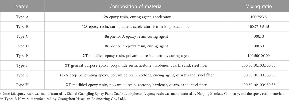
TABLE 1. Mixing ratio design of load transfer materials.
To evaluate the strength and hardening characteristics of the load transfer materials, a large number of resin samples were prepared with curing times of 7, 14, and 28 days according to the mixing ratios of the eight materials mentioned above. The preparation process involved six steps: dosing materials, blending, pouring, curing, demolding, and polishing and cutting. The samples were demolded 48 h after pouring and then maintained at a temperature of 18°C ± 2°C and humidity of 50%. Upon completion, the YBZ2×2(1.5)-50(63) oil pump with the YDC-650 center hole jack was used for a UCS test. The key process for the preparation of load transfer materials and the mechanical test is shown in Figure 1A. Each group contained three epoxy resin material samples to eliminate the errors resulting from sample discreteness. Furthermore, the ratio of the UCS of the material at 7 days to that at 28 days were selected to evaluate the early strength. The test results are shown in Figure 1B.
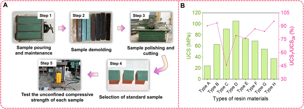
FIGURE 1. UCS test preparation steps and test results of different loading transfer materials: (A) UCS test preparation steps, (B) UCS test results of eight loading transfer materials.
As shown in Figure 1B, Type D resin has the highest UCS, and after 7 days of curing, the strength of Type H resin can reach more than 95% of the final UCS. According to the early strength ratio of the eight resins, Type B, D, and F resins have high UCS and a high hardening efficiency. Hence, these three resins could be considered to have good performance.
3 Design and test process of BFRP anchor systems
Mechanical anchorage is one of the most widely used methods among rock mass reinforcement methods. The wedge is generally made of high-stiffness steel in the traditional mechanical anchor system. However, steel wedges cannot be directly applied as anchors to FRP bars due to the notch effect. Thus, it is important to either modify the steel wedge or design a new anchor system. In this case, reducing the wedge stiffness, protecting the BFRP bars, or using a bonded anchor system may be effective methods. In this study, four anchor systems and tested their ultimate bearing capacity were developed. These four anchor systems are the wedge-modified anchor system, the steel sleeve-protected BFRP anchor system, the threaded steel-pipe-bonded anchor system, and the steel strand–BFRP bar composite anchor system.
3.1 Wedge-modified anchor system
When modifying the wedge, we directly use an epoxy resin wedge to hold the BFRP bar, as shown in Figure 2A. In this design, the epoxy resin wedge reduces the stiffness of the wedge tip.
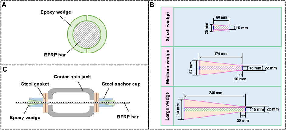
FIGURE 2. Structure of key components in the TSAS and the corresponding tension device: (A) Wedge holding methods in WMAS, (B) Epoxy wedges with different sizes, (C) Tension device of the TSAS.
The wedge size usually has a strong impact on the wedge holding force. In this test, three types of epoxy wedges were made with different sizes, namely, large, medium, and small wedges, as shown in Figure 2B. The inner wall of these wedges has internal threads with a tooth height of 2–2.5 mm. Type B and F resins were chosen to make these epoxy wedges because they harden rapidly and have high strength. Under these conditions, wedge fabrication was more rapid, and the wedge could withstand high stress.
In this test, the diameter of the BFRP bar was 12.6 mm, and the corresponding strength and elastic modulus were 1,170 MPa and 45 GPa, respectively. Depending on whether sand was bonded to the surface, BFRP bars were divided into sand-bonded BFRP bars and smooth BFRP bars. Five groups of tensioning tests were carried out by YDC-650 center hole jack and YBZ2×2(1.5)-50(63) oil pump, as shown in Table 2. Resin wedges were used in Groups J1-J4, and a 40Cr steel wedge with a coating group was used in Group J5. When tensioning the BFRP bar, the load was applied at a constant rate of 100 MPa/min based on the Chinese Standard JGJ 85–2010. When the load reached 20% and 40% of the nominal UBC of the BFRP bar, the load was maintained for 10 min. After the load reached 50% of the nominal UBC, the load was maintained for 20 min. Then, the loading was continually applied until the WMAS failed. The corresponding tensioning test device is shown in Figure 2C.
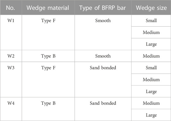
TABLE 2. Tensioning test design of the WMAS under static load.
3.2 Steel sleeve-protected BFRP anchor system
In addition to WMAS, we also fabricated the SBAS wedge anchor system. With a steel sleeve bonded to the outside of the BFRP bar and clamped by the wedge, in this structure the steel sleeve rather than the BFRP bar bears the radial pressure at the wedge tip. Bivalve, trivalve, and seamless steel sleeves with a length of 300 mm were used in this test. The bivalve and trivalve steel sleeves were processed by cutting equally along the axes of the seamless steel sleeves with a laser. To bond the steel sleeve to the BFRP bar as a single unit, Type D resin with the highest strength was chosen as a bonding medium. The BFRP bars used in this test are the same as for WMAS, and the wedge is made of 40Cr Steel, with a length of 48.8 mm and an inclination of 6°. When the BFRP bars were tensioned, three pieces of wedges held the steel sleeves. To increase the roughness of the inner face of the steel sleeve, a part of the inner wall of the steel sleeve was sandblasted. The cross-sectional view of these three bonded structures is shown in Figures 3A–C. Note that the hose clamp was only used in the bonding process and should be removed prior to tensioning.
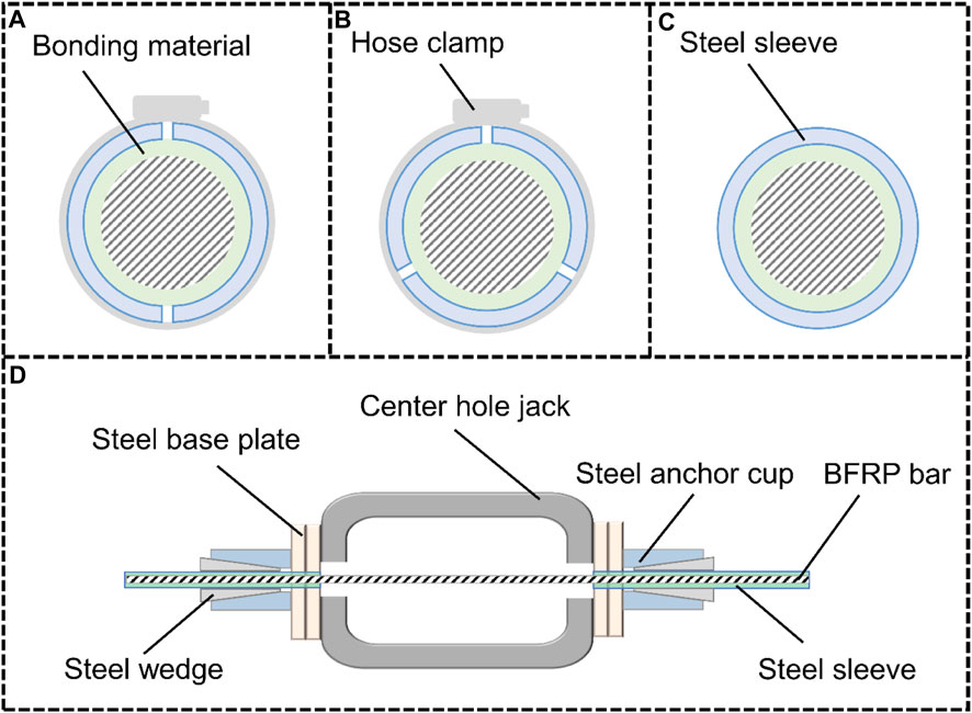
FIGURE 3. Cross-sectional view of bonded structures and the tension device of the SBAS: (A) Bivalve steel sleeve, (B) Trivalve steel sleeve, (C) seamless steel sleeve, (D) Tension device of the SBAS.
The bivalve and trivalve SBAS were tensioned with the center hole jack and the 40Cr Steel wedges, as shown in Figure 3D. The loading method and device were the same as in the WMAS. The seamless SBAS was tensioned by a universal testing machine at a loading speed of 100 MPa/min. Seven sets of static load tests were carried out, and more details about the test parameters are shown in Table 3.
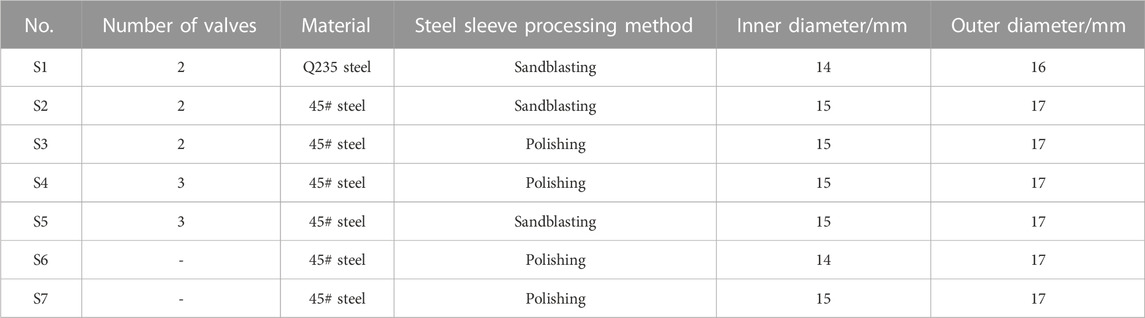
TABLE 3. Tensioning test parameters of the SBAS.
3.3 Threaded steel-pipe-bonded anchor system
Although the mechanical anchor system is widely used, the bonded anchor system is also a reliable option. By bonding BFRP bars and the threaded steel pipe, a new TSAS was also developed, as shown in Figure 4A. The anchor cable was composed of two threaded steel pipes, one BFRP bar, and the bonding medium. Both ends of the BFRP bar were centered in and bonded to the threaded steel pipes. Threads were present on both the inner and outer walls of the steel pipe. Two mutually contacting nuts were installed on the outer wall of every steel pipe, and the steel base plate was set inside the two groups of nuts. When the TSAS was tensioned, the center hole jack directly applied the load to the steel base plate, transferring the load to the threaded steel pipe through the nuts to tension the BFRP bar.
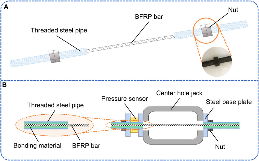
FIGURE 4. Structure of the TSAS and the corresponding tension device: (A) Structure of the TSAS, (B) Tension device of the TSAS.
The bonding medium is important for preventing premature failure of the interfaces of the TSAS. To ensure sufficient strength of the bond interface, Type D resin was also chosen in this test. Some comparative tests were carried out with Types A, B, and C resins. A sand-bonded BFRP bar with a nominal UBC of 145.9 kN was used. For the threaded steel pipe, the outer threads were used to install the necessary nuts, the inner thread was used to increase the contact area between the inner wall and the bonding medium, and the pitch of these two types of threads was 1 mm. During the tensioning tests, the center hole jack and oil pump same as WMAS and SBAS tests were used (Figure 4B), with a single-stage load of 26.3 kN maintained for 10 min. The load on the TSAS was monitored by the center-hole pressure sensor. For the TSAS, eight groups of tests were carried out, and the details of these tests are shown in Table 4.
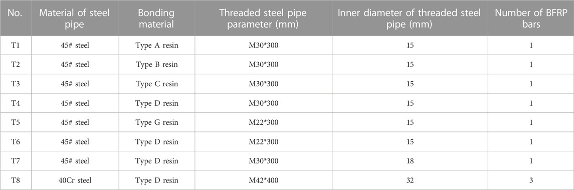
TABLE 4. Tensioning test parameters for the TSAS.
3.4 Steel strand–BFRP bar composite anchor system
Inspired by the structures of the above-mentioned wedge anchor system and bonded anchor system, a steel strand–BFRP bar composite pressure-type anchor system that combines the advantages of these two typical anchor systems was further developed, as shown in Figure 5A. Three BFRP bars with equal length are bound together as the primary stress component in the SBCAS. One end of the three BFRP bars is bonded to the single-stranded steel strands in the coupler after centering, and the other ends are bonded to the tail bonding pipes. A single steel strand and bonded BFRP bars take half of the length of the coupler. The free end of the steel strand passes through the upper anchor plate, where there are steel wedges for clamping the steel strand. The tail bonding pipe is inserted into the bearing plate. When applying the prestress, the wedge first holds the steel strand, and then the prestress is transferred to the BFRP bar through the coupler.
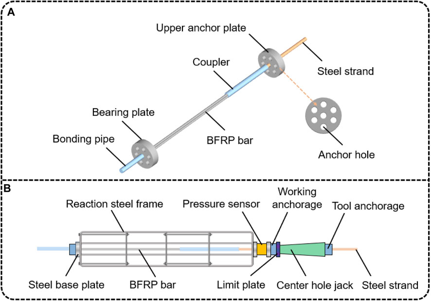
FIGURE 5. Structure of the SBCAS and the corresponding tension device: (A) Structure of the SBCAS, (B) Tension device of the SBCAS.
A 220-cm-long BFRP bar with 20–40 mesh quartz sand on the surface, manufactured by Shanxi ECIC Basalt Development Co., Ltd. was used in this test. This BFRP bar had a tensile strength of 891 MPa. The steel strand had dimensions of 1×7–21.6 mm, and its tensile strength was 1893.7 MPa. Type D resin was poured into the coupler to bond the BFRP bar and the steel strand. With an outer diameter of 38 mm and an inner diameter of 32 mm, the coupler was made of 40Cr steel and has a total length of 80 cm. The tail bonding pipe with a length of 40 cm was also made of 40Cr steel, and a 32 × 1 mm threaded tooth was present on the inner wall.
Prior to the UBC test, a tension test system was assembled, as shown in Figure 5B. The center hole jack applied tension to the steel strand by horizontally pushing the working anchorage. The tail bonding pipe was confined in the bearing plate, the other side of which was provided with a steel base plate in direct contact with the steel reaction frame. This arrangement can convert the tensile force on the BFRP bar into pressure on the reaction frame. The reaction frame was fixed on the ground to provide support for applying prestress to the anchor system. A pressure sensor for the evaluation of the tensile load of the jack was set on the tension side of the anchor system. Two steel base plates were provided on both sides of the pressure sensor. A working anchorage in which a steel wedge was installed to clamp the steel strand was set outside the external steel base plate of the pressure sensor. A limit plate, a center hole jack, and a tool anchorage were arranged in sequence outside the working anchorage.
Some processing parameters of the anchor system (i.e., coupler injection method, steel strand treatment method, and the internal thread pitch of the coupler) were selected as variables in order to evaluate their effects on the UBCs. The three injection methods are as follows:
(1) Water drainage method: fill the water first in the coupler and then pour the Type D resin into the coupler through a catheter to replace the water to ensure that no air bubbles occur.
(2) Direct injection method: Slowly pour the bonding material into the coupler.
(3) Extended injection method: A 10-cm-long PVC pipe was added to the steel strand outlet of the coupler, and the PVC pipe was filled with the bonding material to extend the bonding length of the steel strand.
Since the steel strand surface is smooth and often has oil stains and rust, the bonding interface strength between the bonding material and the steel strand is low, and the rust and oil on the bonding section of all steel strands were removed. Furthermore, surface treatment of the steel strand was carried out with three other methods in this test, namely, paste quartz sand onto the steel strand surface, spray of fine steel shot onto the steel strand surface, and 1-mm-deep grooves cut on the steel strand surface at a 3-mm spacing. When carrying out the tests, a YCQ45Q-200 center-hole jack was used. The oil pressure loading gradient of the jack was 2 MPa, and the load was applied at 100 MPa/min until the anchor system failed. More UBC test parameters are listed in Table 5.
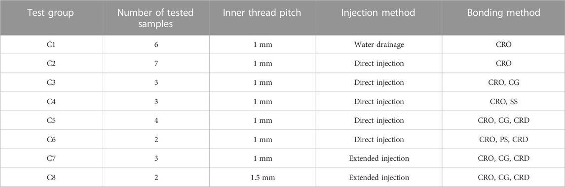
TABLE 5. UBC test parameters for the SBCAS.
4 Test results
4.1 Tensioning test results of WMAS
When the BFRP bar suffers a tension failure, it will burst instantly. However, the BFRP bars did not burst in any of the WMAS tensioning experiments. Four typical failure modes occurred in these tests, as shown in Figures 6A–D. In the first failure mode, a transverse fracture of the BFRP bar occurred, and the wedge tip failed at the same time. In this case, the transverse strength of the anchor cable is still too low to undergo concentrated stress. Within the second failure mode, the wedge was first damaged and slipped from the anchorage. Only slip failure occurred in another failure mode. The lack of friction between the wedge and the BFRP bar led to wedge slipping. In the two tests where large wedges were used (Group W3), the two WMASs had breakage and transverse fracture on the wedge tip, and local splitting failure occurred on the BFRP bar. All tensioning results are shown in Figure 6E, where the four failure modes are marked as Wa–Wd.
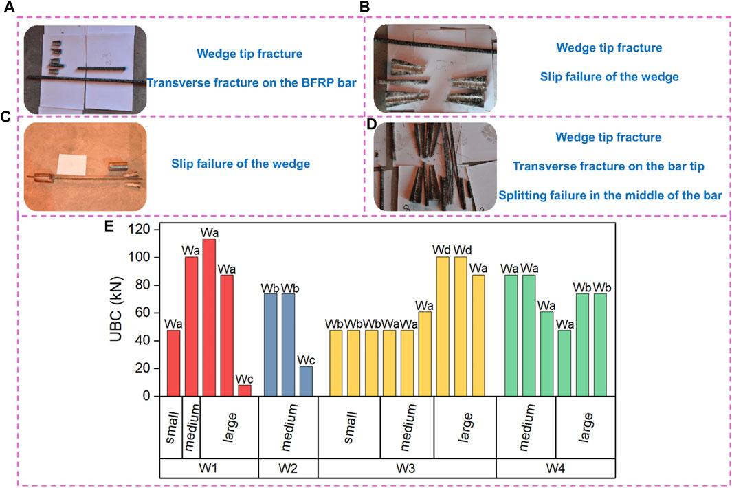
FIGURE 6. Failure modes and UBC test results of the WMASs: (A) Failure mode Wa, (B) Failure mode Wb, (C) Failure mode Wc, (D) Failure mode Wd, (E) UBC test results of WMASs.
Figure 6E indicates that the UBC of the anchor system increased with the increase in the wedge size in W3. When tensioning, a small wedge had slip failure. For medium and large wedges, the BFRP bars showed transverse breakages, and a lower UBC was obtained during slip failure. Note that except for the sample using the large wedge in group W4, the UBC during slip failure in each test group was lower. In groups W1–W4, the wedge material and type of BFRP bar had little impact on the UBC.
During the above tests, because no total bursting failure occurred with the BFRP bars, these WMASs designed in this study are unreliable. The efficiency coefficient of WMAS was less than 0.9; according to Chinese Standard GB/T 14370-2015, this anchor system can also be regarded as ineffective.
4.2 Tensioning test results of SBAS
When tensioning the SBAS with steel wedges, four failure phenomena were observed alone or in combination, as shown in Figures 7A–D. For the two samples in group S1, the steel sleeve containing the BFRP bar exhibited transverse fracture (Figure 7A). Different from group S1, in group S2, the BFRP bars failed along the cross-section, and the wedges popped out from the anchorage with a local fracture (Figure 7B). Another type of failure, the steel sleeve deformed and debonded, was observed with all samples in test groups S3–S5 (Figure 7C). Therefore, a steel wedge cannot be used to tension the BFRP bar when an external steel sleeve protects the BFRP bar. When applying the load by the universal testing machine, all samples in the two groups failed with the bursting of BFRP bars (Figure 7D). In this case, the tensile stress in the BFRP bar was greater than the tensile strength, indicating that the ideal failure mode of the BFRP bar occurred. As long as the steel sleeve was not subjected to an excessive holding force, even if the inner wall of the steel sleeve was only polished, the bonding interface between all components did not fail prior to the bursting of the BFRP bar. The UBCs and failure modes of all samples are shown in Figure 7E, and Sa–Sd represents the four failure phenomena in Figures 7A–D.
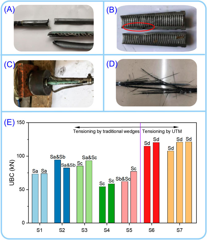
FIGURE 7. Failure modes and UBC test results of the SBAS: (A) Transverse fracture of the BFRP bar (Sa), (B) local fracture of the wedge (Sb), (C) deformation and debonding of the steel sleeve (Sc), (D) BFRP bar bursting (Sd), (E) UBC test results of the SBAS.
Burst failure did not occur in the BFRP bars of groups S1–S5. The BFRP bars in groups S1 and S2 failed with transverse fracture, but the UBC of Group S2 was higher because the strength of #45 steel was higher than that of the Q235 steel. The transverse strength of these two types of steel sleeves is not sufficiently high to overcome the notch effect. The anchor systems in groups S4 and S5 had similar failure modes, but the average UBC in group S5 was greater than that in group S4, demonstrating that sandblasting treatment improved the strength of the interface between the steel sleeve and the bonding medium. The trivalve SBASs had a lower UBC than those using bivalve steel sleeves because a greater number of slits in the steel sleeve resulted in lower strength and made it more difficult to resist the external load. After the steel sleeve deformed, it was prone to separating from the bonding medium, causing failure of the anchor system. When the wedge anchorage was not employed, all samples in groups S6–7 failed by bursting, demonstrating that the strength of the interface between the bonding medium and polished steel sleeve was sufficient to maintain the interface completely prior to the bursting of the BFRP bar. In this case, the inner wall of the steel sleeve does not need sandblasting treatment.
4.3 Tensioning test results of TSAS
When loading the TSAS, three different failure modes occurred in the test results, as shown in Figures 8A–D. When the interface strength of the threaded steel pipe and bonding medium is low, slip failure will occur at the bond interface (Figure 8A). The bursting of the BFRP bar also occurred, indicating that the tensile stress in the bar reached the tensile strength, as shown in Figure 8B. The third failure mode was the failure of the threaded steel pipe, which appeared in one sample of group T6, as shown in Figure 8C. The UBCs and the corresponding failure modes are shown in Figure 8D, where the failure modes in Figures 8A–C were marked as Ta–Tc.
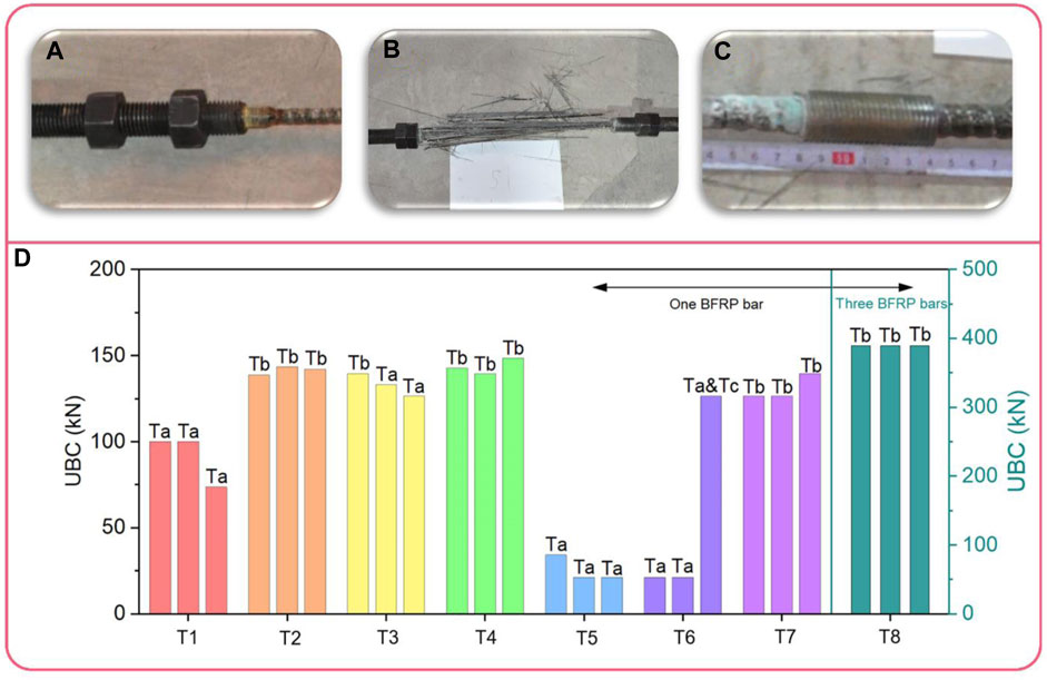
FIGURE 8. Failure modes and UBC test results of the TSAS: (A) Slip failure of the interface (Ta), (B) BFRP bar bursting (Tb), (C) Fracture of the threaded steel pipe (Tc), (D) UBC test results of the TSAS.
Four types of bonding materials were used in T1–T4, and the corresponding slip–load curves for the anchor systems were monitored. All failures of the anchor system in test group T1 were caused by the failure of the interface between the inner wall of the threaded steel pipe and the bonding material. In both groups T2 and T4, all BFRP bars underwent burst failures. This result indicated that the strength of the bonding between Types B and D materials and the threaded steel pipe was sufficient to lead to tension failure of the BFRP bar. For group T3, the interfaces between the bonding material and the threaded steel pipe of the two bonded anchor cables were damaged, and the BFRP bar from one anchor cable underwent burst failure. This result may be associated with the curing process of Type C resin. Since the Type C resin contains a small amount of curing agent, when tensioned, the epoxy resin in some samples may not be completely cured, resulting in low interface strength.
The monitored slip–load curves are given in Figure 9. When using the Type A and C resins as bonding media, the slip–load curves show obvious plastic stages, which is not conducive to the application of prestress. The slip amounts of Type B and D resins both increase linearly with increasing tensile load, demonstrating that they were always in the elastic stage under tensioning. The anchor cable using Type D resin slipped more under the same load. When anchoring the rock mass toward slope treatment or another rock engineering, the reinforced rock mass may deform strongly. Therefore, the anchor cable used in this condition should exhibit larger deformation in the elastic stage to ensure the coordination of deformation between the anchor cable and the rock mass. Although the BFRP bars failed by bursting in group T2, the Type D resin is considered better.
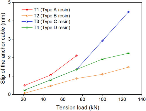
FIGURE 9. Slip–load curves of TSAS with different resins.
The inner interface of the threaded steel pipe in group T5 detached, and two BFRP bars in group T6 showed interface failure. This result occurred because when the tension load increased, the friction and chemical bonding force on the interface between the bonding material and the steel pipe decreased with the deformation until the interface failed. During this process, the BFRP bar was not damaged. Combined with the tension test results of group T4, it is found that if the steel pipe has a low thickness, the bonding medium easily slips from the steel pipe with the BFRP bar wrapped. In the third sample of group T6, the threaded steel pipe failed with 1 mm threads with a length of 8 cm provided at both ends of this pipe. Upon completion of steel pipe bonding, the bonding media at both ends were slightly thicker than those in the middle. The teeth between the threads and the bonding media are not easily continuously cut off, improving the bonding strength of the interface. Nevertheless, the third sample in group T6 finally failed due to the fracture of the steel pipe. Therefore, when BFRP bars were bonded with threaded steel pipes, pipes with thicker walls should be selected.
In addition to groups T2 and T4, the bursting of the BFRP bar also occurred in groups T7 and T8. With the same bonding material, the average UBC of group T7 was slightly lower than that of group T4, indicating that an increase in the inner diameter of the steel pipe may adversely influence the UBC. The average UBC of groups T4 and T7 was 142.415 kN, with an anchorage efficiency coefficient of 97.7%. All BFRP bars in group T8 also underwent burst failures. The average UBC of a single BFRP bar was only 129.86 kN because the “buckets effect” arises when multiple BFRP bars were subjected to loads simultaneously. In this case, if one of the BFRP bars broke first, the tension load on the other two BFRP bars would instantaneously exceed the tensile strength. As a result, the three BFRP bars in a single threaded steel pipe broke off together. In this case, the UBC of the anchor system depends on the BFRP bar that failed first.
4.4 Tensioning test results of SBCAS
After tensioning tests, four failure modes were observed with the failure of SBCAS. These four failure modes were slipping out of the steel strand (Figure 10A), slip failure of the steel strand (Figure 10B), BFRP bar bursting (Figure 10C) and fracture of the coupler (Figure 10D). They can be simply called Sa–Sd. The average UBC and the corresponding failure mode are shown in Figure 10E.
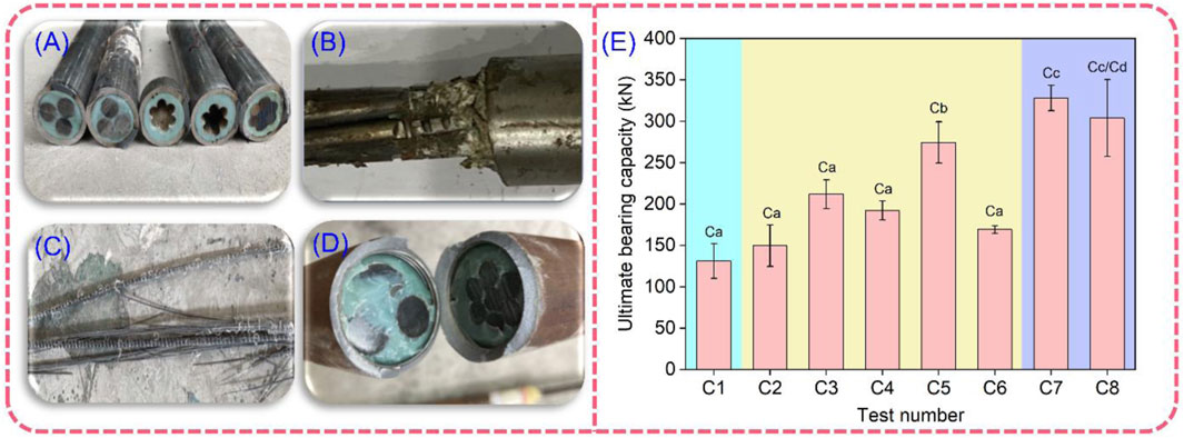
FIGURE 10. Failure modes of the SBCASs and UBC of SBCAS with different manufacturing parameters: (A) Slipping out of the steel strand (Ca), (B) Slip failure of the steel strand (Cb), (C) BFRP bar bursting (Cc), (D) Fracture of the coupler (Cd), (E) UBC test results of SBCASs.
The samples of groups C1–C4 and C6 had the same failure mode, but their average UBCs differed. Although the strength of the interface between the resin and the steel strand in these five groups is too low and could not ensure the bursting of the BFRP bar, the results indicate that the processing method of SBCAS is important for the interface strength. The UBC of SBCAS using water drainage is lower than that using the direct injection method because in the water drainage method, the water attached to the steel strand surface may weaken the adhesive force. Even if the use of the water drainage method can avoid the creation of air bubbles during the bonding process, the bond strength of the soaked steel strand to the epoxy resin was also reduced. Therefore, the drainage method is not recommended. The CG, SS, PS, and CRD treatments all helped increase the UBC to varying degrees. For the treatment methods of steel strands, the best bonding method is CG, followed by SS, while PS is the worst.
All BFRP bars in test group C7 burst, other parts of the anchoring structure were undamaged, and the anchorage efficiency coefficient was 98.5%, indicating that the extended injection method was better than the direct injection method. In one sample of group C8, the tail bonding pipe was first crushed, and the BFRP bar burst; in another test, the coupler fractured, and then the BFRP bar burst. When using the coupler with an internal thread of 1.5 mm, the UBC of the anchor system was lower than that using the coupler with an internal thread of 1 mm.
5 Discussion
To develop an effective BFRP bar anchor system for rock mass reinforcement, four BFRP bar anchor systems were designed. It is indicated from laboratory tensioning tests that, two anchor systems (TSAS and SBCAS) were identified as feasible, and other anchor systems (WMAS and SBAS) were demonstrated to be unusable. The test results demonstrate that both TSAS and SBCAS can achieve a good anchor effect. Moreover, the processing method and structure of these two anchor systems are also very simple. It should be noted that they also have some shortcomings. For TSAS, the tension load needs to be applied through the nut. The nut has a certain thickness. When multiple BFRP anchor cables were expected to use in one borehole, the thickness of the nut may limit the number of BFRP bars. For the SBCAS, the processing of the anchor system is time-consuming due to the pre-treatment of the steel strands and couplers. In the future, better designs may alleviate these problems.
Due to funding limitations, only a number of tests with limited parameters were carried out in this study. The failure modes and mechanical properties of anchor systems depend strongly on the material used, particularly on the types of steel pipes and resin materials. In the future, more types of load transfer materials and steel pipes should be used to develop more anchor systems, and more precise tests should be carried out, which will not only help us further develop an improved anchor system but also help to understand the coupling effect of different components on the UBC. For the WMAS, when the wedge strength is too high, a transverse fracture of the BFRP bar will occur. By contrast, if the wedge strength is too low, the wedge will fracture during tensioning. Currently, it is difficult to find a suitable material for making wedges directly. However, in future work, a flexible coating inside the steel wedge can be set to overcome the notch effect. For the SBAS, when tensioning with wedge anchors, the relative strength of the steel sleeve and the wedge is critical. The size of the wedge must be considered further. The effectiveness of the remaining two anchor systems has been demonstrated. Several possible directions can be pursued for the further optimization of these anchor systems. In this study, their failure mode and mechanical properties were investigated, but the production costs of anchor systems were still not taken into account. In fact, a superior anchor system requires not only good anchoring properties and a simple production process but also low production costs. Future work should focus on reducing production costs and simplifying the production process while ensuring the performance of these anchor systems.
6 Conclusion
(1) The failure modes of wedge-modified anchor systems include transverse fracture of the basalt fiber-reinforced polymer bar and wedge slip failure. The corresponding efficiency coefficient is less than 90%. The modified resin wedges in this study were not applicable to basalt fiber-reinforced polymer bars.
(2) When a wedge anchorage is used to load a steel sleeve-protected BFRP anchor system, the failure modes of bivalve and trivalve steel sleeve-protected BFRP anchor systems include transverse fracture of the basalt fiber-reinforced polymer bar, deformation and debonding of the sleeve, and breakage and pop-up of the wedge. However, when tensioning the anchor system by the universal testing machine, bursting of the basalt fiber-reinforced polymer bar occurred in the anchor system with a basalt fiber-reinforced polymer bar bonded in a seamless steel sleeve.
(3) When one basalt fiber-reinforced polymer bar was bonded in a #45 steel pipe, the maximum anchorage efficiency coefficient of the threaded steel-pipe-bonded anchor system reached 97.7%. When three basalt fiber-reinforced polymer bars were bonded in a 40Cr steel pipe, even if the basalt fiber-reinforced polymer bar in this threaded steel-pipe-bonded anchor system still burst, the average ultimate bearing capacity of each basalt fiber-reinforced polymer bar decreased due to the bucket effect. The threaded steel-pipe-bonded anchor system is a reliable anchor system.
(4) For the steel strand–basalt fiber-reinforced polymer bar composite anchor system, the internal thread pitch of the couple should be 1 mm rather than 1.5 mm. The composite anchor system subject to steel strand grooving, coupler rust removal and drying, and extended injection has the highest ultimate bearing capacity, with an anchorage efficiency coefficient of 98.5%. It is regarded as an effective basalt fiber-reinforced polymer anchor system.
Data availability statement
The original contributions presented in the study are included in the article/Supplementary material, further inquiries can be directed to the corresponding author.
Author contributions
ZD: Conceptualization, Funding acquisition, Writing. SZ: Supervision, Writing-Review and Editing. YY: Methodology, Supervision. XF: Formal analysis, Visualization. YZ: Investigation, Writing—Review and Editing. JG: Data Curation, Resources. ZD: Data Curation, Validation. YT: Investigation, Data Curation. XW: Investigation.
Funding
This work was supported by a follow-up of the Geological Disaster Prevention and Control Project in the Three Gorges area (Grant No. 000121 2019C C60 001 and Grant No. 000121 2021C C60 001), the Natural Science Foundation of Hubei Province (Grant No. 2020CFB352), Qianlong Plan Top Talent Project of Wuhan Center of China Geological Survey (Grant No. QL2022-06), the Fundamental Research Funds for National University, China University of Geosciences (Wuhan) (Grant No. CUGDCJJ202217), and the Key Consulting Project of Chinese Academy of Engineering (Grant No. 2021-XZ-1). The second author thanks the China Scholarship Council for the financial support of his studying in Finland (Grant No. 202106410041).
Conflict of interest
The authors declare that the research was conducted in the absence of any commercial or financial relationships that could be construed as a potential conflict of interest.
Publisher’s note
All claims expressed in this article are solely those of the authors and do not necessarily represent those of their affiliated organizations, or those of the publisher, the editors and the reviewers. Any product that may be evaluated in this article, or claim that may be made by its manufacturer, is not guaranteed or endorsed by the publisher.
Abbreviations
BFRP, Basalt fiber-reinforced polymer; CRD, Cleaned of rust in the coupler and dried; CG, Cut grooves; CRO, Cleaned of rust and oil; PS, Paste quartz sand on the steel strand; SBCAS, Steel strand–BFRP bar composite anchor system; SBAS, Steel sleeve-protected BFRP anchor system; SS, Sprayed fine steel shot; TSAS, Threaded steel-pipe-bonded anchor system; UBC, Ultimate bearing capacity; UCS, Uniaxial compressive strength; WMAS: Wedge-modified anchor system.
References
Brown, E. T. (2015). Rock engineering design of post-tensioned anchors for dams–a review. J. Rock Mech. Geotech. 7, 1–13. doi:10.1016/j.jrmge.2014.08.001
Cao, J., Zhang, N., Wang, S., Qian, D., and Xie, Z. (2020). Physical model test study on support of super pre-stressed anchor in the mining engineering. Eng. Fail Anal. 118, 104833. doi:10.1016/j.engfailanal.2020.104833
Feng, J., Wang, Y., Wu, H., Lai, B., and Xie, X. (2019a). Field pullout tests of basalt fiber-reinforced polymer ground anchor. Rock Soil Mech. 40, 2563–2573. doi:10.16285/j.rsm.2018.0552
Feng, J., Wang, Y., Zhang, Y., Huang, L., He, C., and Wu, H. (2019b). Experimental comparison of anchorage performance between basalt fiber and steel bars. Rock Soil Mech. 40, 4185–4193. doi:10.16285/j.rsm.2018.1640
Feng, J., Zhou, Y., Wang, P., Wang, B., Zhou, J., Chen, H., et al. (2017). Experimental research on blast-resistance of one-way concrete slabs reinforced by BFRP bars under close-in explosion. Eng. Struct. 150, 550–561. doi:10.1016/j.engstruct.2017.07.074
Furse, C., Smith, P., and Diamond, M. (2009). Feasibility of reflectometry for nondestructive evaluation of prestressed concrete anchors. IEEE Sens. J. 9, 1322–1329. doi:10.1109/jsen.2009.2019309
Gao, S., Chen, J., Zuo, C., Wang, W., and Sun, Y. (2016). Structure optimization for the support system in soft rock tunnel based on numerical analysis and field monitoring. Geotech. Geol. Eng. 34, 1089–1099. doi:10.1007/s10706-016-0029-3
Gao, X., Xie, Q., Zhao, W., and Hu, Y. (2017). Experimental study on determining design parameters of non-prestressed BFRP anchor for supporting soil slope. J. Highw. Transp. Res. Dev. 34, 20–28+36. doi:10.3969/j.issn.1002-0268.2017.07.004
Guo, J., Zhang, P., Zhang, Q., Huang, B., and Qin, Z. (2020). Study on landslide hazard identification Technology based on multispectral remote sensing images in Wu gorge. Geol. Mineral Resour. South China 36 (2), 38–45. doi:10.3969/j.issn.1007-3701.2020.01.005
Inman, M., Thorhallsson, E. R., and Azrague, K. (2017). A mechanical and environmental assessment and comparison of basalt fibre reinforced polymer (BFRP) rebar and steel rebar in concrete beams. Energy Procedia 111, 31–40. doi:10.1016/j.egypro.2017.03.005
Ivanović, A., and Neilson, R. D. (2013). Non-destructive testing of rock bolts for estimating total bolt length. Int. J. Rock Mech. Min. 64, 36–43. doi:10.1016/j.ijrmms.2013.08.017
Koca, M. Y., Kincal, C., Arslan, A. T., and Yilmaz, H. R. (2011). Anchor application in karatepe andesite rock slope, izmir—Türkiye. Izmir—Türkiye. Int. J. Rock Mech. Min. 48, 245–258. doi:10.1016/j.ijrmms.2010.11.006
Lan, Y., Zhang, R., Jin, L., and Du, X. (2022). Impact performance of BFRP and steel-reinforced concrete beams with different span-to-depth ratios: Numerical and analytical studies. Sci. China Technol. Sci. 66, 301–319. doi:10.1007/s11431-022-2206-2
Li, C., Zhang, R., Zhu, J., Liu, Z., Lu, B., Wang, B., et al. (2020). Model test of the stability degradation of a prestressed anchored rock slope system in a corrosive environment. J. Mt. Sci-Engl 17, 2548–2561. doi:10.1007/s11629-019-5835-7
Li, S., Guo, S., Yao, Y., Jin, Z., Shi, C., and Zhu, D. (2021). The effects of aging in seawater and SWSSC and strain rate on the tensile performance of GFRP/BFRP composites: A critical review. Constr. Build. Mater 282, 122534. doi:10.1016/j.conbuildmat.2021.122534
Ma, F., Zeng, Q., Lu, X., Wu, T., Lu, X., Zhang, T., et al. (2021). Electrochemical study of stainless steel anchor bolt corrosion initiation in corrosive underground water. Processes 9, 1553. doi:10.3390/pr9091553
Meikle, T., Tadolini, S. C., Sainsbury, B. A., and Bolton, J. (2017). Laboratory and field testing of bolting systems subjected to highly corrosive environments. Int. J. Min. Sci. Tech. 27, 101–106. doi:10.1016/j.ijmst.2016.11.017
Mohamed, O. A., Al Hawat, W., and Keshawarz, M. (2021). Durability and mechanical properties of concrete reinforced with basalt fiber-reinforced polymer (BFRP) bars: Towards sustainable infrastructure. Polymers 13, 1402. doi:10.3390/polym13091402
Motwani, P., Perogamvros, N., Taylor, S., and Laskar, A. (2020). Performance of industrial wedge-anchors for pre-stressing BFRP bars: Experimental and numerical studies. Compos. Struct. 251, 112592. doi:10.1016/j.compstruct.2020.112592
Shan, R., Huang, P., Yuan, H., Meng, C., and Zhang, S. (2022). Research on the full-section anchor cable and C-shaped tube support system of mining roadway in island coal faces. J. Asian Archit. Build. 21, 298–310. doi:10.1080/13467581.2020.1869556
Shi, J., Wang, X., Zhang, L., Wu, Z., and Zhu, Z. (2022). Composite-wedge anchorage for fiber-reinforced polymer tendons. J. Compos Constr. 26, 04022005. doi:10.1061/(asce)cc.1943-5614.0001194
Shi, Z. M., Liu, L., Peng, M., Liu, C. C., Tao, F. J., and Liu, C. S. (2018). Non-destructive testing of full-length bonded rock bolts based on HHT signal analysis. J. Appl. Geophys. 151, 47–65. doi:10.1016/j.jappgeo.2018.02.001
Sun, X., Zhang, B., Gan, L., Tao, Z., and Zhao, C. (2019). Application of constant resistance and large deformation anchor cable in soft rock highway tunnel. Adv. Civ. Eng. 2019, 1–19. doi:10.1155/2019/4347302
Tistel, J., Grimstad, G., and Eiksund, G. (2017). Testing and modeling of cyclically loaded rock anchors. J. Rock Mech. Geotech. 9 (6), 1010–1030. doi:10.1016/j.jrmge.2017.07.005
Wang, J., Huang, B., Zhao, Y., Zhang, Z., and Hu, M. (2018). Study on deformation and failure mechanism of huangnanbeixi dangerous rock in three Gorges reservoir area. Geol. Mineral Resour. South China 34 (4), 339–346. doi:10.3969/j.issn.1007-3701.2018.04.009
Wang, X., Shi, J., Wu, G., Yang, L., and Wu, Z. (2015). Effectiveness of basalt FRP tendons for strengthening of RC beams through the external prestressing technique. Eng. Struct. 101, 34–44. doi:10.1016/j.engstruct.2015.06.052
Wang, X., Zhou, J., Ding, L., Song, J., and Wu, Z. (2020). Static behavior of circumferential stress-releasing anchor for large-capacity FRP cable. J. Bridge Eng. 25, 04019127. doi:10.1061/(asce)be.1943-5592.0001504
Wang, Y., Sun, X., and Ren, A. (2019). Investigations of rock anchor corrosion and its influence factors by exhumations in four typical field sites. Eng. Fail Anal. 101, 357–382. doi:10.1016/j.engfailanal.2019.03.022
Wu, Z., and Yamamoto, M. (2013). “Study on the basic performance of FRP-concrete Structures using basalt fibre reinforced polymer rods,” in The 68th Annual Meeting of the Japan Society of Civil Engineers JSCE. (in Japanese).
Xia, D., Tang, H., Sun, S., Tang, C., and Zhang, B. (2022). Landslide susceptibility mapping based on the germinal center optimization algorithm and support vector classification. Remote Sens. 14 (11), 2707. doi:10.3390/rs14112707
Xu, H., and Li, Q. (2011). Factors affecting the dynamic response of pre-stressed anchors after transient excitation. Min. Sci. Technol. (China) 21, 395–399. doi:10.1016/j.mstc.2011.05.018
Xu, M., Tang, Y., Liu, X., Yang, H., and Luo, B. (2018). A shaking table model test on a rock slope anchored with adaptive anchor cables. Int. J. Rock Mech. Min. 112, 201–208. doi:10.1016/j.ijrmms.2018.10.021
Xu, X., Rawat, P., Shi, Y., and Zhu, D. (2019). Tensile mechanical properties of basalt fiber reinforced polymer tendons at low to intermediate strain rates. Compos Part B-Eng 177, 107442. doi:10.1016/j.compositesb.2019.107442
Yang, G., Zhong, Z., Zhang, Y., and Fu, X. (2015). Optimal design of anchor cables for slope reinforcement based on stress and displacement fields. J. Rock Mech. Geotech. 7, 411–420. doi:10.1016/j.jrmge.2015.04.004
Yi, H., Liu, W., Zhang, X., Yang, H., Yu, H., and Li, L. (2014). Study on deformation mechanism of high stress and broken roadway and its controlling measures. Appl. Mech. Mater 501, 1798–1803. doi:10.4028/www.scientific.net/amm.501-504.1798
Yin, Z., Zhao, B., and Ye, R. (2022). Identification of potential landslides in the head area of the Three Gorges Reservoir based on time series InSAR. South China Geol. 38, 273–280. doi:10.3969/j.issn.2097-0013.2022.02.008
Zhang, H. (2015). Preparation and properties of electroless plating coating on anchor rod in support engineering. Taiyuan, China: Taiyuan University of Technology.
Zhao, C., Tang, Z., Wang, P., Feng, J., Zhou, J., Kong, X., et al. (2022). Blast responses of shallow-buried prefabricated modular concrete tunnels reinforced by BFRP-steel bars. Undergr. Space 7, 184–198. doi:10.1016/j.undsp.2021.07.004
Zhao, W., Wang, H., Chen, Y., and Hu, Y. (2016). Laboratory and field tests use of BFRP anchor bolt in supporting soil slope. J. Eng. Geol. 24, 1008–1015. doi:10.13544/j.cnki.jeg.2016.05.032
Zheng, H., Shi, Z., Haas, D. T., Shen, D., Hanley, K. J., and Li, B. (2022). Characteristics of the impact pressure of debris flows. J. Geophys Res-Earth 127, e2021JF006488. doi:10.1029/2021jf006488
Zheng, H., Shi, Z., Yu, S., Fan, X., Hanley, K. J., and Feng, S. (2021). Erosion mechanisms of debris flow on the sediment bed. Water Resour. Res. 57, e2021WR030707. doi:10.1029/2021wr030707
Zheng, K., Shi, C., Lin, Y., Lei, M., and Liu, J. (2021). Transfer station cracks induced by cutting anchor cables and crack stabilization: A case study. Eng. Fail Anal. 126, 105460. doi:10.1016/j.engfailanal.2021.105460
Zhou, S., Yao, Y., Luo, X., Jiang, N., and Niu, S. (2023). Dynamic response evaluation for single-hole bench carbon dioxide blasting based on the novel SSA–VMD–PCC method. Int. J. Geomech. 23, 04022248. doi:10.1061/(asce)gm.1943-5622.0002589
Zhu, B., Song, Y., Wang, H., and Li, Y. (2020). Coupling effect of creep deformation and prestress loss of anchored jointed rock. Adv. Civ. Eng. 2020, 1–10. doi:10.1155/2020/8850975
Keywords: basalt fiber-reinforced polymer bar, rock anchoring, anchor system, ultimate bearing capacity, failure mode
Citation: Dai Z, Zhou S, Yin Y, Fu X, Zhang Y, Guo J, Du Z, Tao Y and Wu X (2023) Experimental study on the mechanical properties and failure modes of BFRP bar anchor systems under static tension loading. Front. Earth Sci. 11:1106920. doi: 10.3389/feart.2023.1106920
Received: 24 November 2022; Accepted: 27 February 2023;
Published: 13 March 2023.
Edited by:
Biswajeet Pradhan, University of Technology Sydney, AustraliaReviewed by:
Jianqi Zhuang, Chang’an University, ChinaHongchao Zheng, Tongji University, China
Kun He, Southwest Jiaotong University, China
Copyright © 2023 Dai, Zhou, Yin, Fu, Zhang, Guo, Du, Tao and Wu. This is an open-access article distributed under the terms of the Creative Commons Attribution License (CC BY). The use, distribution or reproduction in other forums is permitted, provided the original author(s) and the copyright owner(s) are credited and that the original publication in this journal is cited, in accordance with accepted academic practice. No use, distribution or reproduction is permitted which does not comply with these terms.
*Correspondence: Shengtao Zhou, c3R6aG91QGN1Zy5lZHUuY24=