 Hong Li1Qing Wang1Kun Zhang2Qing Hui Zhang3Tao Song2Chuang Zhang4Lu Bin Zhuo1Chen Hao1Fu Ping Feng5
 He Yuan Wang5*Yin Quan Zhang5
- 1CNPC Engineering Technology Research Institute Co., Ltd., Beijing, China
- 2Petrochina Daqing Oilfield Company Limited, Daqing, China
- 3PetroChina Qinghai Oilfield Third Oil Production Factory, Mangai, China
- 4PetroChina Qinghai Oilfield Drilling and Production Technology Research Institute, Dunhuang, China
- 5Key Laboratory of Ministry of Education of China on Enhanced Oil and Gas Recovery, Institute of Petroleum Engineering, Northeast Petroleum University, Daqing, China
In the process of drilling, the drilling fluid will invade into the bedding plane of shale under the action of pressure difference that will cause hydration collapse and wellbore instability. In order to ensure the wellbore stability during shale oil and gas drilling, it is necessary to clarify the invasion law of drilling fluid along bedding fractures during the drilling process. The immersion experiment method is often used to study the invasion law of drilling fluid, which is quite different from the actual invasion process of drilling fluid underground. In this paper, the depth of drilling fluid invasion into shale under different confining pressures and displacement times is intuitively and accurately determined by the displacement experiment and NMR scanning first. Also, then the mathematical relationships between drilling fluid invasion depth and invasion time, invasion pressure difference, confining pressure, bedding angle, and drilling fluid viscosity were established. The errors between the calculated values of the drilling fluid invasion depth and the experimental values were less than 15%, and the calculation accuracy was high. In addition to the influence of invasion time, formation pressure difference and confining pressure on invasion depth were researched through the method of numerical simulation. The results showed that the liquid invasion depth increased logarithmically with the increase of invasion time and formation pressure difference, but it grew slowly in the later period and tended to be stable; the invasion depth decreased exponentially with the increase of confining pressure, bedding plane angle, and drilling fluid viscosity. The results in the paper provide a basis for the subsequent determination of the collapse pressure and collapse period of bedding shale.
1 Introduction
Shale oil and gas are important unconventional resources and are becoming more and more important in oil and gas production. At present, there are more and more serious wellbore instability problems in the drilling process of shale oil and gas wells (Chen et al., 2003; Akbarpour and Abdideh, 2020; Aslannezhad et al., 2020), and the instability proportion is as high as 90% (Chen et al., 2014; Liu, 2014; Liu et al., 2021). Many factors will lead to wellbore instability, such as wellbore stress concentration caused by wellbore formation, vibration of the drilling tool assembly during drilling, and changes in formation rock properties caused by invasion of drilling fluid into the formation. The wellbore stress concentration caused by the formation of the wellbore and the vibration of the BHA during drilling are mainly related to the actual working conditions on site. The rules of drilling fluid invasion into the formation were mainly studied, and the basic data for the study of wellbore stability were provided in this paper. In the process of overbalanced drilling, the liquid column pressure is greater than the formation pressure. Under the action of pressure difference, the drilling fluid filtrate will invade the formation, especially the shale with well-developed bedding fractures, which will cause hydration expansion, crushing and disintegration of shale, and then lead to the reduction of rock strength and wellbore instability (Mody and Hale, 1993; Shi and Xia, 2011). Such phenomena of rock strength deterioration and wellbore instability caused by drilling fluid intrusion are quite common. Therefore, in order to solve the problem of shale wellbore instability, it is necessary to clarify the deterioration law of the shale strength after drilling fluid intrusions into bedding shale so as to provide a basis for determining the collapse pressure, the collapse period of bedding shale, the selection of drilling fluid density, and the determination of control measures. Laboratory experiments are usually adopted by the researchers in order to study the process of drilling fluid invasion into shale. In a laboratory experiment, the immersion method is usually adopted, in which the shale samples are immersed in the drilling fluid and then the drilling fluid filtrate invades the shale sample in all directions under the action of capillary force (Lin et al., 2022; Liu et al., 2022). However, the drilling fluid invades the shale reservoir only from the wall of the well along the radial axis of the wellbore in the actual drilling process. Therefore, there is a great difference between the immersion method and the actual underground invasion process in the study of drilling fluid invasion into shale. So, the accuracy of the shale strength deterioration law obtained from this experiment also needs to be discussed.
Therefore, in Section 2, the displacement experiment and nuclear magnetic resonance experiment were carried out to explore the change of invasion depth under different displacement times, displacement pressure, and confining pressure. In Section 3, the physical model was established for numerical simulation, the accuracy of the model was verified according to the comparison of the results of the simulation pre-experiment, and the single-factor influence law of drilling fluid invasion was analyzed. Finally, the content of this paper is summarized in Section 4. The method of displacement experiment and numerical simulation were adopted in this paper in order to study the law of drilling fluid invasion along the shale bedding fractures. The influence factors of drilling fluid invasion depth were confirmed, and the mathematical relationships between the invasion depth and a variety of factors were established at last, which provided the basis of accurate data for subsequent studies to determine the degradation law of the borehole strength at different positions around the borehole. The displacement experiment method adopted in the study could realize the one-way invasion of drilling fluid into shale along the end face of the core column under a certain pressure difference, which was more consistent with the actual working conditions than that with the immersion method.
2 Experiment of drilling fluid invasion
2.1 Materials
The composition of the drilling fluid was diesel oil + 3% main emulsion + 1% auxiliary emulsion + 3% organic soil + 3% fluid loss reducer + 2% calcium oxide + 2% superfine calcium carbonate + 1% film forming and blocking agent + 0.7% nano-polymer. The standard core column size is φ25 × 50 mm, which was obtained from shale reservoir at 2550 m depth (Figure 1), and the bedding fracture size obtained from the CT experiment is 160.94 μm (Figure 2).
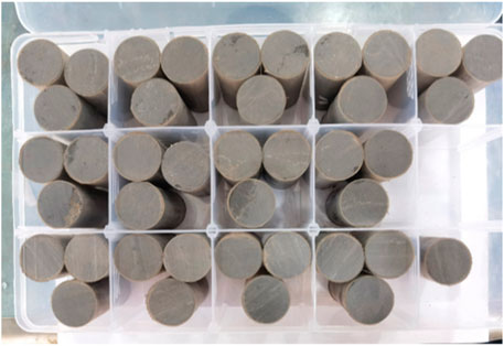
FIGURE 1. Core samples.
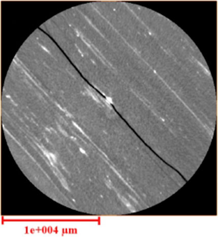
FIGURE 2. CT scanning results.
The experimental equipment used in this paper includes a WCS-FCJ non-isothermal steam oil displacement thermostat, Nantong Zhongjing Machinery Co., Ltd.; an HAS-100HSB constant pressure constant speed pump, Beijing Satellite Manufacturing Factory; a core gripper [4.5 × 4.5 × 30/50/80 (cm)], ZR-3 intermediate vessel, back pressure valve, differential pressure transmitter, and data acquisition system, Hai’an County Petroleum Scientific Research Instrument Co., Ltd.; and a MesoMR low-field nuclear magnetic resonance scanner, Nerl Miay Company (Figure 3).
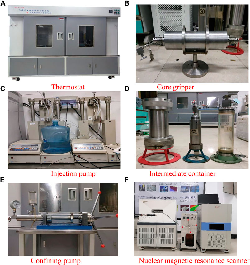
FIGURE 3. Experimental apparatus, (A) thermostat, (B) core gripper, (C) injection pump (D) intermediate container, (E) confining pump, and (F) nuclear magnetic resonance scanner.
2.2 Methods
2.2.1 Drilling fluid invasion experiment
The drilling fluid invasion experiment was carried out with the displacement experimental device. First, the standard core column (φ25 × 50 mm) was dried, and then, it was inserted into the middle container and was vacuumized using a vacuum pump; then, it was saturated with fluorine oil by connecting to a liquid tank. Then, the standard core column saturated with fluorine oil was taken out and put into the core holder. Next, the drilling fluid invaded into the standard core column using a high-voltage drive device along one end face, and the whole process was carried out at a constant temperature. In the aforementioned experiments, the invasion pressure difference is the pressure difference of the formation borehole, and the confining pressure is larger than the invasion pressure difference by 2–3 MPa. In fact, the invasion time, invasion pressure, and the invasion temperature could be changed according to the actual formation conditions. In this paper, the specific conditions of the invasion experiment are shown, as in Table 1.
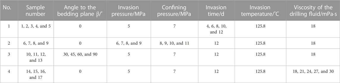
TABLE 1. Drilling fluid invasion test conditions.
2.2.2 Determination of drilling fluid invasion depth
The core column samples obtained under different invasion conditions in Section 2.2.1 were sealed to prevent the volatilization of the invading liquid, and then, they were placed in the low-field NMR scanner (Nerl Miay) for hydrogen atom signal scanning and detection. The core column has been saturated with fluorine oil before drilling fluid invasion, so there was no hydrogen atom in the core column. Therefore, the hydrogen atom signals captured by NMR scanning were all from the invading drilling fluid. Along the invasion direction of drilling fluid in NMR imaging, the distance between the farthest imaging point of the hydrogen atom signal and the starting point of invasion is the invasion depth of the drilling fluid. It could be observed from the NMR T2 spectrum, the smaller the pore, the greater the relaxation time, and the larger the pore, the smaller the relaxation time. According to the comparison of hydrogen atom signal peaks with different relaxation times, the intrusion of hydrogen atoms into rocks along the matrix and bedding fractures could be judged. It is also found that the drilling fluid invaded less along small pores and more along bedding fractures (Figure 4A). As can be observed from NMR imaging, the yellow bright spot in the figure is the signal of the hydrogen atom from the invading drilling fluid (Figure 4B). The invasion depth of the drilling fluid in shale core can be calculated according to the ratio of the distance between the farthest imaging point of the hydrogen atom signal and the beginning of invasion in the overall core image.
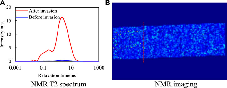
FIGURE 4. NMR spectrum. (A) NMR T2 spectrum. (B) NMR imaging.
2.3 Experimental results
2.3.1 Variation of invasion depth under different invasion times
The invasion depth of drilling fluid under different invasion times was tested under the conditions of invasion pressure, 5 MPa; confining pressure, 7 MPa; invasion temperature, 125.8°C; angle to the bedding plane, 0°; and the viscosity of the drilling fluid, 18 mPa·s. The results are shown in Figure 5.
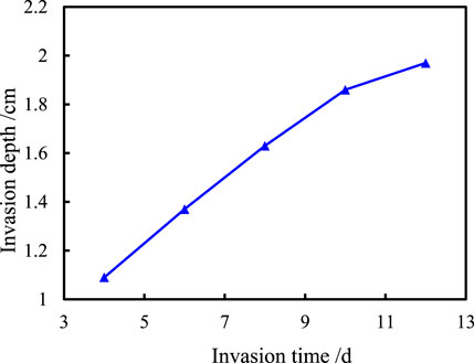
FIGURE 5. Invasion depth of the drilling fluid at different invasion times.
Clearly, the invasion depth increases apparently first but gives modest growth with the increase of invasion time. When the invasion pressure difference is constant, the contacting surface between the drilling fluid and shale pore and fracture increases with the increase of invasion time, and then, the friction resistance increases, which results in the invasion pressure difference being gradually consumed, so the invasion depth decreases.
2.3.2 Variation of invasion depth under different confining pressures
The invasion depth of the drilling fluid under different confining pressures was tested, when the invasion temperature was fixed at 125.8°C, the invasion time was 12 days, the angle to the bedding plane was 0°, and the viscosity of the drilling fluid was 18 mPa·s. The results are shown in Figure 6.
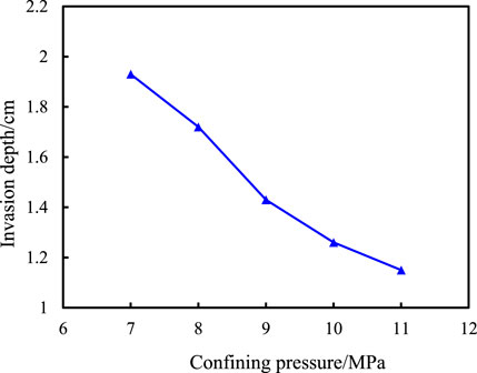
FIGURE 6. Variation of drilling fluid invasion depth with confining pressure.
As can be observed, with the increase of confining pressure, the invasion depth of the drilling fluid gradually decreases. This is because with the increase of confining pressure, the pore structure of the rock is gradually compressed and the pore size of shale fracture is gradually closed, which leads to the gradual decrease in core permeability and porosity. The invasion resistance becomes bigger and bigger, which decreases the invasion depth of the drilling fluid along the bedding fracture.
2.3.3 Variation of invasion depth under different angles to the bedding plane
The invasion depth of the drilling fluid under different angles to the bedding plane was tested under the conditions of the invasion pressure of 5 MPa, confining pressure of 7 MPa, invasion temperature of 125.8°C, invasion time of 12 days, and the viscosity of drilling fluid of 18 mPa·s. The results are shown in Figure 7.
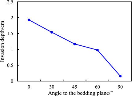
FIGURE 7. Invasion depth of the drilling fluid at different angles to the bedding plane.
As shown in Figure 7, the invasion depth of the drilling fluid gradually decreases with the increase of the angle to the bedding plane. This is because with the increase of the angle to the bedding plane, the resistance of the drilling fluid to intrusion along the bedding joint gradually increases, which results in the gradual decrease in the intrusion depth of the drilling fluid along the bedding joint. When the angle to the bedding plane is 90°, the drilling fluid cannot invade along the bedding plane but can only invade along the rock matrix. Due to the small porosity of the matrix, the invasion depth is basically unchanged.
2.3.4 Variation of invasion depth under different viscosities of the drilling fluid
The invasion depth of drilling fluid under different viscosities of the drilling fluid was tested under the conditions of invasion pressure of 5 MPa, confining pressure of 7 MPa, invasion temperature of 125.8°C, invasion time of 12 days, and angle to the bedding plane of 0°. The results are shown in Figure 8.
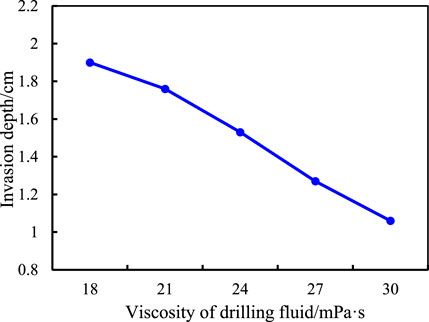
FIGURE 8. Invasion depth of the drilling fluid at different viscosities of the drilling fluid.
As can be observed, with the increase of drilling fluid viscosity, the invasion depth of drilling fluid gradually decreases. This is because as the viscosity of drilling fluid increases, the resistance of drilling fluid invading along the bedding joints gradually increases, which results in the gradual decrease in the depth of drilling fluid invading along the bedding joints.
3 Numerical simulation of drilling fluid invading the bedding shale
The law of drilling fluid invasion into the shale bedding fracture can be examined intuitively and accurately by using the invasion experiment. However, due to the limited indoor conditions and cost problems, the indoor experiment cannot provide all the real mechanical and environmental conditions of the underground shale reservoir. Therefore, it is necessary to use the numerical simulation method to further study the process of drilling fluid invasion on the basis of experimental study results. The drilling fluid invasion model was established based on Darcy’s law and fracture opening model, and then, the law of drilling fluid invasion of shale was further comprehensively explored using the finite element method.
3.1 Physical model
In order to simulate the process of drilling fluid invasion into bedding shale under different conditions, a physical model should be established first. In this paper, the finite element software COMSOL was used to construct a layered shale physical model, in which the Darcy flow and fracture flow were selected as the physical fields. The cylindrical model was established according to the core size (Figure 9A). The bedding fracture pore size, porosity, and permeability of shale in the physical model were set according to the performance parameters of shale (Figure 9B). The injection end and pressure of the injection end were marked, and the invasion depth of drilling fluid along bedding fractures was simulated and analyzed at different invasion times under the action of specified invasion pressure. Unstructured grids are used to divide the computing domain. The number of grids is 113545.
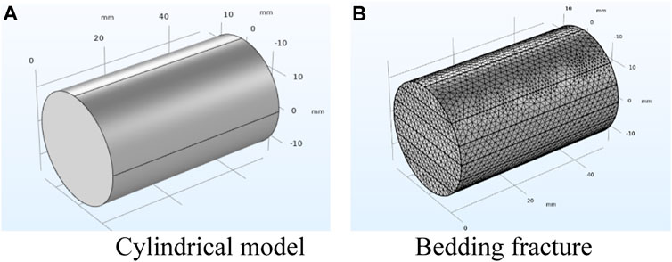
FIGURE 9. Physical model. (A) Cylindrical model; (B) bedding fracture.
In the physical model, there were many parameters, such as invasion pressure, confining pressure, core permeability, porosity, and pore size of bedding fractures. The multiple variables were solved simultaneously by parametric scanning so as to obtain the influence of each parameter on the model results. Specific parameters are shown in Table 2.
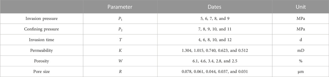
TABLE 2. Parameters.
The seepage velocity of the fluid can be expressed by Darcy’s law (Yang et al., 2022) as follows:
1 v——velocity of the fluid flow, m/s.
2 μ——fluid viscosity, mPas.
3r——invasion depth from the wellbore center to fracture, m.
4 p——the liquid column pressure at m from the fracture in the center of the wellbore, MPa.
Considering that the fracture opening of a single bedding fracture changes with the change of fluid pressure, the opening of bedding fracture when drilling fluid invades into the fracture at depth r is (Cao, 2016)
1 b——the opening of the bedding fracture at any section, m.
2 b0——the opening of the bedding fracture at fluid pressure p0, m.
3 p (r) ——the liquid column pressure at r distance from the center fracture of the wellbore, MPa.
4 p0——original formation pressure, MPa.
5 Kn——stiffness coefficient of the bedding fracture, MPa/m.
The change of the opening of bedding fracture with pressure drop when the drilling fluid intrusion depth is r could be calculated as follows:
1 pi——well fluid column pressure, MPa.
2 ri——wellbore radius, m.
The average flow velocity equation of the fluid in the bedding fracture was applied to the horizontal radial flow model, and then, the flow velocity formula of the drilling fluid through the fracture surface was obtained as follows (Yang et al., 2022):
1 n——power–law index of the drilling fluid.
2 Kci——consistency index of the drilling fluid, Pasn.
When there is no leakage in the borehole, the mass balance equation of incompressible fluid is
At a certain invasion time, the relationship between the change of bedding fracture opening and the change of pressure drop is
The flow equation of the drilling fluid with the change of the opening of the bedding fracture from the borehole wall to the bedding fracture at the finite length fracture is obtained as follows (Zhu et al., 2021):
3.2 Numerical simulation calculation and accuracy verification of drilling fluid invasion depth
3.2.1 Simulation prediction and accuracy analysis of invasion depth under different invasion times
According to the parameters in Table 2, the injection end pressure and confining pressure are, respectively, fixed at 5 MPa and 7 MPa, and then, the processes of drilling fluid invasion into shale under different invasion times were simulated, as shown in Figure 10i.
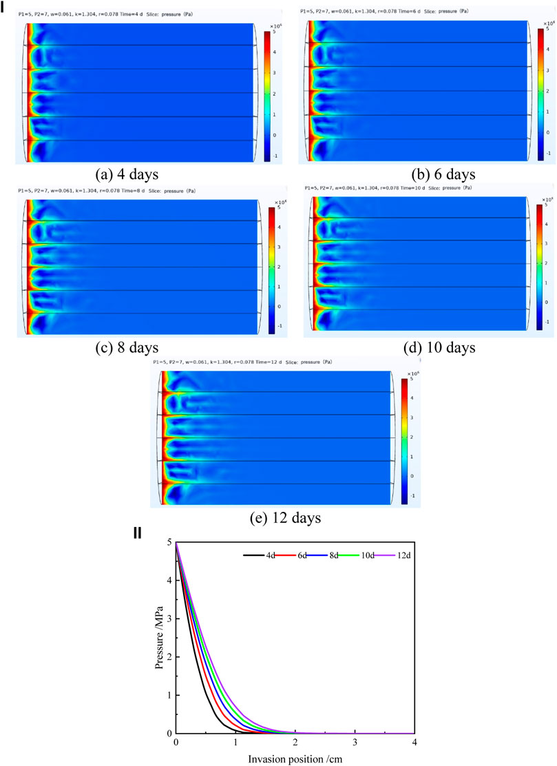
FIGURE 10. (i): Cloud diagram of the invasion effect at different invasion times. (A) 4 days, (B) 6 days, (C) 8 days, (D) 10 days, and (E) 12 days. (ii): Changes of pressure between bedding fractures with the invasion position at different invasion times.
As shown in Figure 10i, with the extension of invasion time, the degree of fluid pressure declines along the bedding fracture (according to the variation trend of dark red, light red, yellow, light blue, and dark blue in the cloud image) is significantly higher than that along the matrix, and this rule becomes more and more obvious with the increase of invasion time. This is because the permeability, porosity, and pore size of the bedding fractures are much larger than those of the matrix. Under the action of pressure difference, the fluid pressure decreases faster when the permeability, porosity, and pore size of the shale are larger. Therefore, at the same time, the invasion depth of the drilling fluid in the bedding fractures is greater than that of the matrix (the furthest distance between the intersection points of light blue and dark blue in the cloud image and the penetration end is the invasion depth of the drilling fluid).
Also, as shown in Figure 10i, under the same conditions, the invasion degree of the drilling fluid along bedding fractures is much greater than that of matrix, and bedding fractures are more prone to deteriorate after invasion. Therefore, it is necessary to further explore the pressure variation law at each position in the bedding fracture at different invasion times so as to provide a foundation for determining the relationship between the depth and the invasion time of the drilling fluid along the bedding fracture.
The vector diagram of pressure and invasion position under different invasion times is shown in Figure 10ii, in which the invasion position of the drilling fluid in the core is taken as the abscissa and the fluid pressure in the bedding fracture calculated by the model is taken as the ordinate.
As shown in Figure 10ii, the fluid pressure between bedding fractures gradually decreases with the increase of the invasion degree under a fixed displacement time. The degree of pressure drop varies with the invasion time. When the invasion position is the same, the shorter the invasion time and the faster the pressure drop.
As shown in Figure 10ii, the distance between the invasion position when the fluid pressure is 0 MPa, and the origin is defined as the invasion depth of the drilling fluid. Error analysis was made between the calculated values and the experimental values of drilling fluid invasion depth along bedding fractures at different invasion times (Table 3).
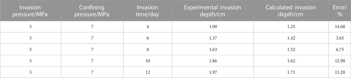
TABLE 3. Calculated and experimental values of invasion depth under different invasion times.
According to the comprehensive analysis of errors, the errors between the calculated value of the model and the measured value of the experiment are within 15%, indicating that the model has good prediction accuracy. The drilling fluid invasion depth can be accurately predicted at different invasion times by the model.
3.2.2 Simulation prediction and accuracy analysis of intrusion depth under different invasion pressures and confining pressures
Due to the compaction of the overlying strata, the permeability, porosity, and pore size of the core will change under different confining and driving pressures, which will affect the invasion process of the drilling fluid along the bedding fracture. Therefore, it is necessary to predict the invasion depth of the drilling fluid along the bedding fracture under different confining and invasion pressures. Thus, the invasion process of the drilling fluid along the bedding fracture was simulated under different invasion pressures and confining pressures when the invasion time was fixed at 12 days, and the results are shown in Figure 11i.
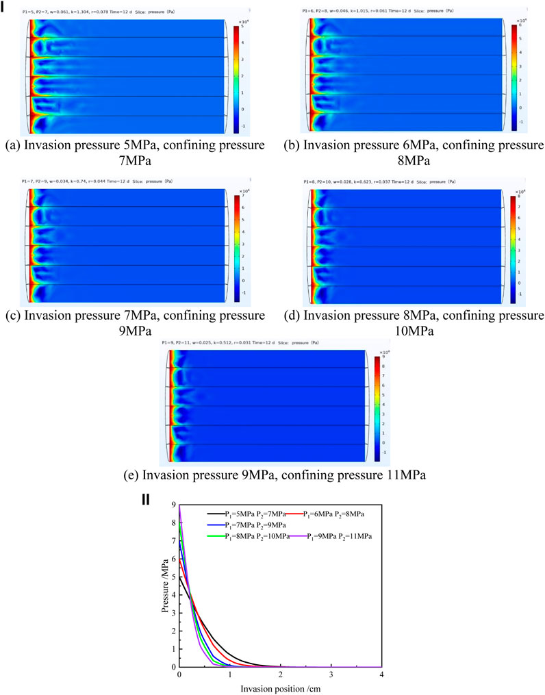
FIGURE 11. (i): Cloud diagram of the invasion effect under different invasion and confining pressures. (A) Invasion pressure 5 MPa, confining pressure 7 MPa, (B) invasion pressure 6 MPa, confining pressure 8 MPa, (C) invasion pressure 7 MPa, confining pressure 9 MPa, (D) invasion pressure 8 MPa, confining pressure 10 MPa, (E) invasion pressure 9 MPa, and confining pressure 11 MPa. (ii): Changes of fluid pressure between bedding fractures with invasion position under different invasion and confining pressures.
As shown in Figure 11i, with the increase of invasion pressure and confining pressure, the degree of fluid invasion along the bedding fracture and matrix becomes smaller, and the degree of reduction along the bedding fracture is significantly higher than that of the matrix.
In order to further study the mathematical relationship between the invasion depth and invasion pressure and confining pressure in bedding fractures, the vector diagram of pressure and invasion position under different invasion pressures and confining pressures was drawn (Figure 11ii), in which the invasion position of the drilling fluid in the core was taken as the abscissa and the fluid pressure in bedding fractures calculated by the model was taken as the ordinate. As shown in Figure 11ii, under a certain invasion pressure and confining pressure, the fluid pressure between bedding fractures gradually decreases with the increase of the invasion degree. With different invasion and confining pressures, the degree of pressure drop between bedding fractures is also different. The greater the invasion pressure and confining pressure, the more obvious the pressure drop.
Error analysis was made between the calculated values and the experimental values of drilling fluid invasion depth along bedding fractures under different invasion pressures and confining pressures (Table 4).
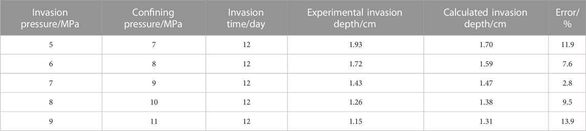
TABLE 4. Calculated and experimental values of invasion depth under different invasion pressures and confining pressures.
A shown in Table 4, the errors between the simulated calculated value and the experimental measured value of the invasion depth under different invasion pressures and confining pressures are within 14%, indicating that the model has good prediction accuracy. The model can accurately predict the invasion depth of drilling fluid along the bedding fractures under different invasion pressures and confining pressures.
3.2.3 Simulation prediction and accuracy analysis of intrusion depth under different angles to the bedding plane
A major feature of stratum rational strata is that there is a set of nearly parallel stratum surfaces, and its three-dimensional spatial state (production form) is generally described by the stratum surface trend, tendency, and inclination, in which the inclination of the stratum surface has a very large impact on the stability of the well wall. The weakening effects of the stratum after being subjected to the action of the drilling fluid are different when the inclination angle changes, so it is necessary to consider the influence of drilling fluid invasion along different inclination angles of the layer surface on the stability of the well wall.
According to the parameters in Table 2, the process of the drilling fluid invading to the shale at different bedding plane angles is simulated by fixing the injection end pressure, displacement confining pressure, and displacement time, as shown in Figure 12i.
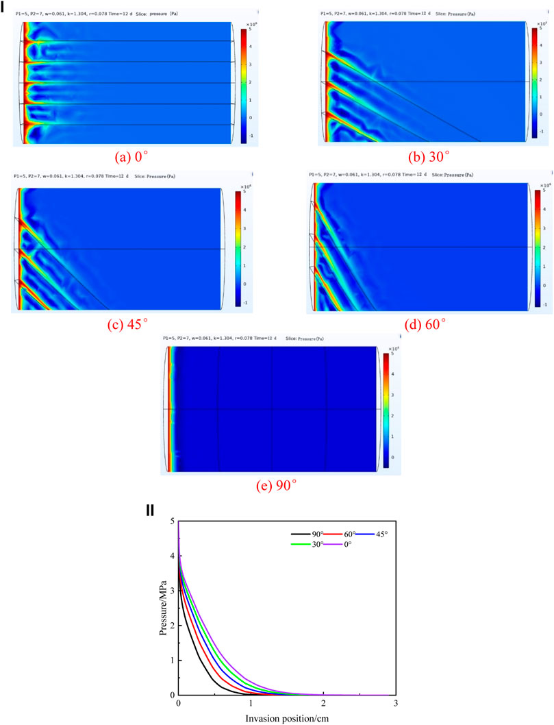
FIGURE 12. (i): Cloud diagram of the invasion effect under different angles to the bedding plane. (A) 0, (B) 30, (C) 45, (D) 60, and (E) 90. (ii): Changes of fluid pressure between bedding fractures with the invasion position under different angles to the bedding plane.
The vector diagram of pressure and invasion position under different angles to the bedding plane is shown in Figure 12ii, in which the invasion position of the drilling fluid in the core is taken as the abscissa and the fluid pressure in the bedding fracture calculated by the model is taken as the ordinate.
As shown in Figure 12ii, the fluid pressure between the layers of fractures gradually decreases with the increase of the degree of intrusion during the fixed displacement time. The degree of pressure drop varies with the changes of the inclination angle. When the intrusion position is the same, the greater the inclination angle, the faster the pressure drop.
Error analysis was made between the calculated values and the experimental values of drilling fluid invasion depths along bedding fractures under different angles to the bedding plane (Table 5).
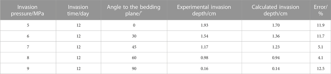
TABLE 5. Calculated and experimental values of invasion depth under different angles to the bedding plane.
As shown in Table 5, the errors between the calculated and experimental values of invasion depth under different angles to the bedding plane are within 13%, indicating that the model has good prediction accuracy and the model can accurately predict the invasion depth of the drilling fluid along the bedding fractures under different angles to the bedding plane.
3.2.4 Simulation prediction and accuracy analysis of intrusion depth under different viscosities of the drilling fluid
According to the parameters in Table 2, the process of the drilling fluid invading shale at different viscosities of the drilling fluid is simulated by fixing the injection end pressure, displacement confining pressure, and displacement time, as shown in Figure 13i.
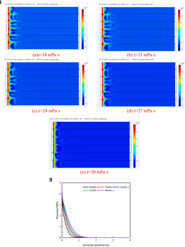
FIGURE 13. (i): Cloud diagram of the invasion effect under different viscosities of the drilling fluid. (A) τ = 18 mPa·s, (B) τ = 21 mPa·s, (C) τ = 24 mPa·s, (D) τ = 27 mPa·s, and (E) τ = 30 mPa·s. (ii): Changes of fluid pressure between bedding fractures with the invasion position under different viscosities of the drilling fluid.
The vector diagram of pressure and invasion position under different viscosities is as shown in Figure 13ii, in which the invasion position of the drilling fluid in the core was taken as the abscissa and the fluid pressure in bedding fractures calculated by the model was taken as the ordinate. As shown in Figure 13ii, under a certain invasion pressure and confining pressure, the fluid pressure between bedding fractures gradually decreases with the increase of the invasion degree. With different viscosities of the drilling fluid, the degree of pressure drop between bedding fractures is also different. The greater the viscosity of the drilling fluid, the more obvious the pressure drop.
Error analysis was made between the calculated values and the experimental values of drilling fluid invasion depth along bedding fractures under different viscosities of the drilling fluid (Table 6).
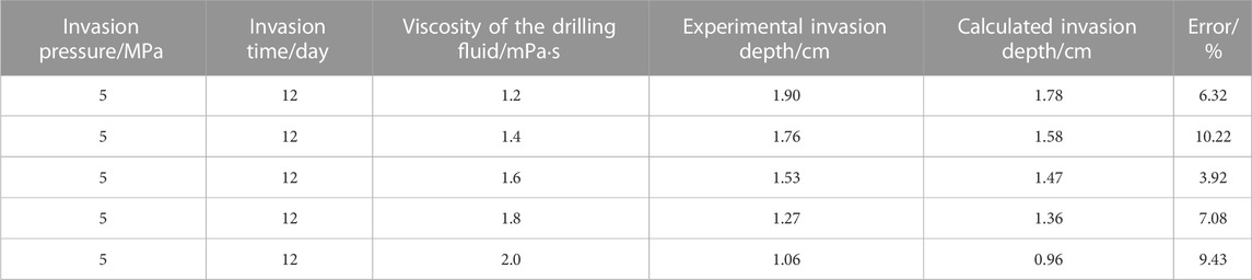
TABLE 6. Calculated and experimental values of invasion depth under different viscosities of the drilling fluid.
As shown in Table 6, the errors between the simulated calculated value and the experimental measured value of the invasion depth under different viscosities of the drilling fluid are within 11%, indicating that the model has good prediction accuracy. The model can accurately predict the invasion depth of the drilling fluid along the bedding fractures under different viscosities of the drilling fluid.
3.3 Analysis of drilling fluid invasion along the bedding fracture
3.3.1 Variation law of invasion depth with invasion time
When the drilling fluid has been contacting with the formation for different times, the invasion depth will change accordingly. In order to clarify the change law of drilling fluid invasion depth along bedding fractures with invasion time, the invasion pressure at this time was fixed as 5 MPa and the confining pressure was 7 MPa, the bedding plane angle is 0°, and the viscosity of drilling fluid is 18 mPa·s. With invasion time as abscissa and invasion depth as the ordinate, the vector diagram of invasion depth–invasion time was drawn and mathematical fitting was carried out. Compared to the fitting results of linear, power function, exponential function, and logarithmic function, it is found that the logarithmic function has the highest fitting degree, as shown in Figure 14.
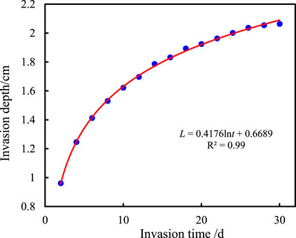
FIGURE 14. Relationship between invasion depth and invasion time of the drilling fluid along the bedding fracture.
As shown in Figure 14, the invasion depth gradually increased with the increase of the invasion time, but the increase in amplitude gradually slowed down and finally tended to be unchanged. This is because with the invasion of the drilling fluid into the bedding fractures, the contact area between the drilling fluid and shale pores gradually increases, and the pore resistance in the invasion process becomes more and more large (Ma et al., 2022; Wang et al., 2022), which then cancels out part of the formation pressure difference that results in the gradual reduction of the driving force of drilling fluid invasion and the growth rate of invasion depth. By fitting, it was found that the invasion depth (L) of the drilling fluid is logarithmic to the invasion time (t), and the specific functional formula is L=0.4176 lnt + 0.6689. The invasion depth of the drilling fluid along bedding fractures at any time under fixed formation pressure difference and confining pressure can be obtained by using this formula.
3.3.2 Variation law of invasion depth with formation pressure difference
The formation pressure difference is the main driving force of the drilling fluid invasion into the shale, which will certainly affect the invasion depth of the drilling fluid. In order to clarify the mathematical relationship between the invasion depth of the drilling fluid along bedding fractures and the formation pressure difference, the invasion time was fixed as 12 days, the confining pressure was 7 MPa, the bedding plane angle is 0°, and the viscosity of drilling fluid is 18 mPa·s. The vector diagram of the penetration depth–formation pressure difference was drawn with the formation pressure difference as abscissa and the invasion depth as the ordinate, and then, mathematical fitting was carried out. Compared to the fitting results of linear, power function, exponential function, and logarithmic function, it is found that the logarithmic function has the highest fitting degree, as shown in Figure 15.
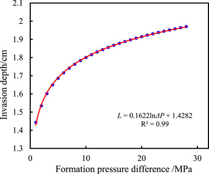
FIGURE 15. Relationship between the invasion depth of the drilling fluid along the bedding fracture and formation pressure difference.
The invasion depth gradually increases with the increase of formation pressure difference, but the growth rate gradually slows down. When the formation pressure difference is greater than 25 MPa, the invasion depth gradually tends to have a fixed value. This is because when the local pressure difference exceeds a certain value, the interfacial drag effect caused by the capillary force becomes particularly significant (Ma et al., 2022; Wang et al., 2022), and these interfacial drag effects are offset with formation pressure, so the invasion depth will not increase. The invasion depth of the drilling fluid is also logarithmic to the formation pressure difference (ΔP), and the specific functional formula is L = 0.1622 ln ΔP + 1.4282. The penetration depth of the drilling fluid along the bedding fracture can be obtained under any formation pressure difference with fixed invasion time and confining pressure using this formula.
3.3.3 Variation law of invasion depth with confining pressure
Due to the compaction of the overlying strata, the permeability, porosity, and pore size of the core change under different confining pressures, which will further affect the invasion process of the drilling fluid along the bedding fracture. Therefore, it is necessary to analyze the change rule of the invasion depth of the drilling fluid along the bedding fracture under different confining pressures. In order to clarify the relationship between the invasion depth of the drilling fluid along bedding fractures and confining pressure, the invasion time was fixed as 12 days, the confining pressure was 7 MPa, the bedding plane angle is 0°, and the viscosity of the drilling fluid is 18 mPa·s. With confining pressure as the abscissa and invasion depth as the ordinate, the vector diagram of invasion depth–confining pressure was drawn, and mathematical fitting was carried out. Compared to the fitting results of linear, power function, exponential function, and logarithmic function, it is found that the exponential function has the highest fitting degree, as shown in Figure 16.
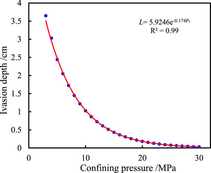
FIGURE 16. Relationship between the invasion depth of the drilling fluid along the bedding fracture and confining pressure.
As shown in Figure 16, the invasion depth of the drilling fluid gradually decreases with the increase of confining pressure and finally approaches 0. This is because with the increase of confining pressure, the pore structure of the rock is gradually compressed, then the pore size, permeability, and porosity of the core are gradually reduced, and the invasion resistance of the drilling fluid is increased, resulting in the decrease in the invasion depth. When the confining pressure increases to a certain value, the bedding fractures are pressed and closed, and the permeability approaches 0, so there is nearly no drilling fluid invading the shale reservoir. Through mathematical fitting, the mathematical relation between the invasion depth of the drilling fluid along the bedding fracture and confining pressure (P2) is determined as L = 5.9246e−0.174P2, and the invasion depth of the drilling fluid along the bedding fracture under any confining pressure with fixed time and formation pressure difference can be obtained by using this formula.
3.3.4 Variation law of invasion depth with the angle to the bedding plane
When the angle of the bedding plane is different, the invasion resistance will also be different. For example, when the bedding plane is 90°, the drilling fluid cannot invade along the bedding plane but only along the rock matrix. The invasion depth must be small because of the matrix with small pores. Therefore, it is necessary to analyze the variation law of invasion depth of the drilling fluid along the bedding fracture under different angles to the bedding plane. In order to clarify the relationship between the invasion depth of the drilling fluid along the bedding fracture and the bedding plane angle, the invasion time is fixed as 12 days, the invasion pressure at this time was fixed as 5 MPa, the confining pressure was 7 MPa, and the viscosity of the drilling fluid is 18 mPa·s. Taking the bedding plane angle as abscissa and invasion depth as the ordinate, the vector diagram of the invasion depth layer with the angle was drawn, and the mathematical fitting of linear, power function, exponential function, and logarithmic function was carried out. The results show that the exponential function has the highest degree of fit, as shown in Figure 17.
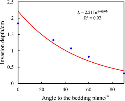
FIGURE 17. Relationship between the invasion depth of the drilling fluid along the bedding fracture and angle to the bedding plane.
As shown in Figure 17, the invasion depth of the drilling fluid gradually decreases with the increase of the bedding plane angle. This is because with the increase of the angle of the bedding plane, the resistance of drilling fluid intrusion along the bedding fracture gradually increases, resulting in gradual decrease in the invasion depth of the drilling fluid along the bedding fracture. When the angle of bedding plane is 90°, the drilling fluid cannot invade along the bedding plane. Due to the small porosity of the matrix, the intrusion depth is basically unchanged. Through mathematical fitting, the mathematical relation between the invasion depth of the drilling fluid and the angle of the bedding plane (Φ) is determined as L = 2.211e−0.019Φ. The invasion depth of the drilling fluid along the bedding fracture under any angle to the bedding plane can be obtained by this formula.
3.3.5 Variation law of invasion depth with viscosity of the drilling fluid
The invasion resistance will be different when the viscosity of the drilling fluid is different, which will affect the invasion process of the drilling fluid along the bedding fractures. Therefore, it is necessary to analyze the variation law of invasion depth of the drilling fluid along the bedding fracture under different viscosities of the drilling fluid. In order to clarify the relationship between the invasion depth of the drilling fluid along the bedding fracture and the viscosity of the drilling fluid, the invasion time is fixed as 12 days, the displacement pressure is 5 MPa, the displacement confining pressure is 7 MPa, and the bedding plane angle is 0°. With the drilling fluid viscosity as the abscissa and the invasion depth as the ordinate, the vector diagram of invasion depth with drilling fluid viscosity was drawn, and mathematical fitting was performed. The results show that the exponential function has the highest degree of fit, as shown in Figure 18.
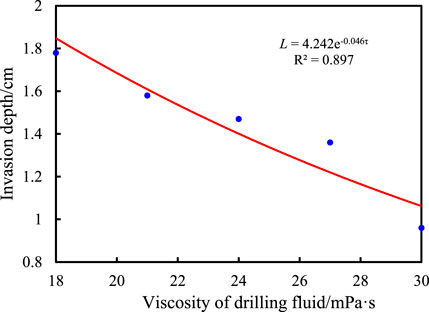
FIGURE 18. Relationship between the invasion depth of the drilling fluid along the bedding fracture and viscosity of the drilling fluid.
As shown in Figure 18, the invasion depth of the drilling fluid gradually decreases with the increase of drilling fluid viscosity. After mathematical fitting, the mathematical relation between the invasion depth of the drilling fluid along the bedding fracture and the viscosity of the drilling fluid (τ) is determined to be L = 4.242e−0.046τ. The invasion depth of the drilling fluid along the bedding fracture can be obtained by using this formula.
4 Conclusion
The laws of drilling fluid invasion along the shale bedding fractures were studied by experiment and numerical simulation, and the following conclusions are derived:
(1) Compared with the static immersion experiment, the method of simulating the drilling fluid invade into shale bedding fractures in the displacement experiment takes into account not only the capillary force but also the influence of liquid column pressure difference on the process of drilling fluid invasion into bedding shale, which realizes the unidirectional invasion of the drilling fluid into shale and is closer to the actual process of drilling fluid filtration into shale.
(2) Based on fissure flow and Darcy flow physical fields, the rational model of drilling fluid invading shale bedding fractures is established and the process of drilling fluid invasion is simulated. Then, the mathematical relationships between the invasion depth and invasion time, formation pressure, confining pressure, bedding angles, and drilling fluid viscosity are defined as L = 0.4176 lnt + 0.6689, L = 0.1622 ln ΔP + 1.4282, L = 5.9246e−0.174P2, L = 2.211 e−0.019Φ, and L = 4.242e−0.046τ. The errors between the calculated values of the drilling fluid invasion depth and the experimental values under different conditions are less than 15%, which shows highly prediction accuracy.
(3) The invasion depth of the drilling fluid along shale bedding has a positive logarithmic relationship with the invasion time and the formation pressure difference. With the increase of the invasion time and the formation pressure difference, the invasion depth gradually increases, but it grows slowly in the later stage and finally tends to be unchanged. There are negative exponential relationships between the invasion depth and confining pressure, the angle of bedding plane, and the viscosity of the drilling fluid. The invasion depths of the drilling fluid decrease when the confining pressure, the angle of bedding plane, and the viscosity of drilling fluid increase. When the bedding angle is 90°, the drilling fluid invades only along the rock matrix.
Data availability statement
The original contributions presented in the study are included in the article/Supplementary Material; further inquiries can be directed to the corresponding author.
Author contributions
HL, QW, and KZ designed research; TS, HW, and LZ performed research; QZ, CZ, and CH analyzed data; HW, FF, and YZ performed the data analyses and wrote the paper. All authors discussed the results and revised the manuscript.
Acknowledgments
The authors are grateful to the Key Laboratory of Ministry of Education P.R.C. in China for financial support.
Conflict of interest
HL, QW, LZ, and CH were employed by CNPC Engineering Technology Research Institute Co., Ltd. KZ and TS were employed by the PetroChina Daqing Oilfield Company Limited. QZ was employed by the PetroChina Qinghai Oilfield Third Oil Production Factory. CZ was employed by the PetroChina Qinghai Oilfield Drilling and Production Technology Research Institute.
The remaining authors declare that the research was conducted in the absence of any commercial or financial relationships that could be construed as a potential conflict of interest.
Publisher’s note
All claims expressed in this article are solely those of the authors and do not necessarily represent those of their affiliated organizations, or those of the publisher, the editors, and the reviewers. Any product that may be evaluated in this article, or claim that may be made by its manufacturer, is not guaranteed or endorsed by the publisher.
References
Akbarpour, M., and Abdideh, M. (2020). Wellbore stability analysis based on geomechanical modeling using finite element method. Model. Earth Syst. Environ. 6 (2), 617–626. doi:10.1007/s40808-020-00716-x
Aslannezhad, M., Keshavarz, A., and Kalantariasl, A. (2020). Evaluation of mechanical, chemical, and thermal effects on wellbore stability using different rock failure criteria. J. Nat. Gas Sci. Eng. 78, 103276. doi:10.1016/j.jngse.2020.103276
Cao, H. T. (2016). Research on fracture surface morphology and seepage characteristics based on fractal theory. Chengdu, China: Chengdu University of Technology.
Chen, P., Ma, T. S., and Xia, H. Q. (2014). Prediction model for collapse and instability of shale horizontal wells with multiple weak planes. Nat. Gas. Ind. 34 (12), 87–93. doi:10.3787/j.issn.1000-0976.2014.12.012
Chen, X., Tan, C. P., and Detournay, C. (2003). A study on wellbore stability in fractured rock masses with impact of mud infiltration. J. Petroleum Sci. Eng. 38 (3-4), 145–154. doi:10.1016/S0920-4105(03)00028-7
Lin, H., Deng, J. G., Xie, T., Liu, H. L., Luo, C., and Liu, W. (2021). Borehole stability of middle-deep mud shale formations in Bozhong area of Bohai Oilfield. Sci. Technol. Eng. 21 (11), 4409–4417. doi:10.3969/j.issn.1671-1815.2021.11.016
Lin, H., Sun, X., Yuan, Y., Lai, X., Qu, H., and Luo, C. (2022). Experimental investigation on the dynamic volume changes of varied-size pores during shale hydration. J. Nat. Gas Sci. Eng. 101, 104506. doi:10.1016/j.jngse.2022.104506
Liu, K. (2014). Study on hydration control method of hard and brittle shale. Si Chuan Sheng, China: Southwest Petroleum University.
Liu, Y., Yang, C., Wang, J., Xiong, Y., and Peng, P. (2022). New insights into hydration-induced creep behavior of shale: A comparison study of brittle black shale and clayey oil shale at micro-scale. Mar. Petroleum Geol. 138, 105554. doi:10.1016/j.marpetgeo.2022.105554
Ma, X., Nguyen, N. N., and Nguyen, A. V. (2022). A review on quantifying the influence of lateral capillary interactions on the particle floatability and stability of particle-laden interfaces. Adv. Colloid Interface Sci. 307, 102731. doi:10.1016/j.cis.2022.102731
Mody, F. K., and Hale, A. H. (1993). Borehole-stability model to couple the mechanics and chemistry of drilling-fluid/shale interactions. J. Petroleum Technol. 45 (11), 1093–1101. doi:10.2118/25728-PA
Shi, B. Z., and Xia, B. R. (2011). Microstructure changes during hydration process of hard and brittle shale. J. Daqing Petroleum Inst. 35 (6), 28–34. doi:10.3969/j.issn.2095-4107.2011.06.005
Wang, L., Ma, F., He, Y., and Liu, D. (2022). The prediction of spontaneous oil-water imbibition in composite capillary. Petroleum 8 (1), 84–91. doi:10.1016/j.petlm.2021.07.001
Yang, H., Li, J., Zhang, G., Zhang, H., Guo, B., and Chen, W. (2022a). Wellbore multiphase flow behaviors during gas invasion in deepwater downhole dual-gradient drilling based on oil-based drilling fluid. Energy Rep. 8, 2843–2858. doi:10.1016/j.egyr.2022.01.244
Yang, S., Li, X., Zhang, K., Yu, Q., and Du, X. (2022b). The coupling effects of pore structure and rock mineralogy on the pre-Darcy behaviors in tight sandstone and shale. J. Petroleum Sci. Eng. 218, 110945. doi:10.1016/j.petrol.2022.110945
Keywords: shale, bedding fractures, drilling fluid invasion, wellbore stability, numerical simulation
Citation: Li H, Wang Q, Zhang K, Zhang QH, Song T, Zhang C, Zhuo LB, Hao C, Feng FP, Wang HY and Zhang YQ (2023) The invasion law of drilling fluid along bedding fractures of shale. Front. Earth Sci. 11:1112441. doi: 10.3389/feart.2023.1112441
Received: 30 November 2022; Accepted: 06 January 2023;
Published: 26 January 2023.
Edited by:
Hongtu Zhang, Henan Polytechnic University, ChinaReviewed by:
Botao Li, Xi’an University of Science and Technology, ChinaChenchen Wang, China University of Mining and Technology, Beijing, China
Juan Zhang, Chongqing University, China
Copyright © 2023 Li, Wang, Zhang, Zhang, Song, Zhang, Zhuo, Hao, Feng, Wang and Zhang. This is an open-access article distributed under the terms of the Creative Commons Attribution License (CC BY). The use, distribution or reproduction in other forums is permitted, provided the original author(s) and the copyright owner(s) are credited and that the original publication in this journal is cited, in accordance with accepted academic practice. No use, distribution or reproduction is permitted which does not comply with these terms.
*Correspondence: He Yuan Wang, MTc3MTkxNDg1ODlAMTYzLmNvbQ==