 Peng Cao
 Xuebing Hu2,3*
 Enlong Liu
- 1State Key Laboratory of Hydraulics and Mountain River Engineering, Department of Geotechnical and Underground Engineering, College of Water Resources and Hydropower, Sichuan University, Chengdu, China
- 2China Merchants Chongqing Communication Research & Design Institute Co. Ltd., Chongqing, China
- 3National Engineering Research Center of Road Tunnel Ltd., Chongqing, China
Taking the Jiangluling Carbonaceous Shale Tunnel as an example, this study aims to investigate the mechanism of large deformation and design construction technology of carbonaceous shale tunnels. Using theoretical analysis and comparative analysis of numerical simulation and field measured data, the mechanism, mechanical properties, and causes of large squeezing deformation of the Jiangluling Tunnel were analyzed. The study results are as follows: 1) Six failure modes of the support structure can be generated due to the large deformation of the surrounding rocks during the construction of Jiangluling Carbonaceous Shale Tunnel; 2) The causes of large deformation during the construction can be divided into internal and external causes; 3) The deformation degree of the surrounding rock of Jiangluling Carbonaceous Shale Tunnel increases with the burial depth in an approximately linear manner. Under deep-buried conditions, horizontal convergence is more severe than vault settlement in carbonaceous shale tunnels; 4) The deformation of the construction cavern of the Jiangluling Carbonaceous Shale Tunnel typically includes the displacement before tunnel face excavation, tunnel face deformation, and deformation behind the tunnel face. The advance displacement accounts for 30.73% of the total displacement. The influence range of advance displacement is 1-1.2D in front of the tunnel face. These results can provide a reference for the design and construction of carbonaceous shale tunnels.
1 Introduction
In China’s Western Development Strategy, the completion of a convenient transportation system is an inevitable demand for economic development and social progress of western regions. In addition, the improvement of the land transportation network is also based on the extension of transportation infrastructure to cold areas with harsh natural conditions at high latitudes and high altitudes. With the rise of railroad and highway construction on the plateau of the Tibetan area in China, the technical aspects of tunnel construction in cold areas with high altitudes are receiving increasing attention from the engineering community. Jiangluling Carbonaceous Shale Tunnel in Gonghe-Yushu Highway, different from carbonaceous shale tunnels at low altitudes, is a special geological condition encountered during construction. Influenced by the environment, the construction process had witnessed hazards such as large deformation, extrusion, and collapse of the surrounding rock, the heave of the tunnel bottom, cracking of the support structure, and lining deformation and failure (GuoLi et al., 2019). At present, as engineering experience and relevant research on the design and construction of carbonaceous shale tunnels in Alpine regions are both relatively scarce worldwide, it is difficult to control the large deformation produced by carbonaceous shale. Therefore, the research on the deformation mechanism as well as design and construction technologies of Jiangluling Carbonaceous Shale Tunnel in Gonghe-Yushu Highway can provide engineering experience for similar carbonaceous shale tunnels in Alpine regions, thus promoting highway construction in Alpine regions.
In recent years, with the development of geotechnical engineering and the progress of science and technology, international research on the complex properties of rock mass mechanics has made great progress. Most research on carbonaceous shale tunnels focused on the mechanical properties, the deformation law and mechanism, and instability failure mechanism of the surrounding rock, and engineering treatment measures. Researchers, such as Wang (Wang, 2010), Tan et al. (Tan et al., 2021), Xie and Chen (Xie and Chen, 2007), and Liu et al. (Gao et al., 2005), have explored the mechanism of large deformation of soft rock tunnels. Studies have shown that the causes of large deformation of tunnels can be attributed to the following two factors: water-swelling behavior of swelling mineral components and squeezing deformation of soft surrounding rocks under high in situ stress.
Zhao (Zhao, 2007) and Sun et al. (Sun and Ling, 1995) analyzed the mechanical properties of large squeezing deformation and explained the definition of squeezing deformation from the perspective of rheology. They classified squeezing deformation as a rheological deformation category with a fast deformation rate and slow convergence rate and systematically analyzed the mechanical mechanism of the occurrence of large squeezing deformation. Dual control measures, prediction of squeezing potential in the preliminary design phase and rating of large deformation in the construction phase, was proposed to overcome large squeezing deformation. Based on theories related to engineering geology and structural mechanics, Tian. (2013) analyzed the deformation and failure mechanism of carbonaceous shale under high in situ stress through the statistical analysis of field monitoring data and sketches of tunnel faces. The influence of bedded rock and soft rock strata on the stability of the tunnel surrounding rock was explored, and the mechanical mechanism of deformation and failure of carbonaceous shale under high in situ stress was revealed. Teng and Tang. (2017), Zhang and Guan. (2000), Tang and Tang. (2012) established a FLAC3d numerical model to analyze the distribution of displacement field, stress field, and seepage field of the tunnel surrounding rock under surrounding rock pressure and groundwater pressure. They have revealed the deformation pattern of carbonaceous shale tunnels under high in situ stress conditions. Some researchers (Duan and Weng, 2012; Gao et al., 2016; Yang, 2016; Bian et al., 2017; Ding et al., 2017) also adopted indoor and outdoor tests, numerical simulations and combined with measured data to study the strength of the surrounding rock, the distribution pattern of the in situ stress field, the range of the surrounding rock broken rock zone, and the macroscopic deformation and failure characteristics of the tunnel. They summarized the deformation law of the surrounding rock for the construction of carbonaceous shale tunnels and proposed control measures for tunnel deformation. The research results provided referential value for the research and analysis of mechanical properties of large deformation in carbonaceous shale tunnels.
In this paper, taking the Jiangluling Carbonaceous Shale Tunnel as an example, the mechanism and mechanical properties of the large deformation of carbonaceous shale tunnels were analyzed through theoretical analysis, numerical calculation, and comparative analysis of field measured data. This research is intended to provide a basis and technical support for similar engineering designs.
2 Analysis of the failure pattern of the surrounding rock on site
Jiangluling Tunnel is located in the Gonghe-Yushu (Jiegu) Highway (National Highway 214) with an altitude of 4,280 m above sea level. It is a typical permafrost highway tunnel in a high-altitude cold area. The left line of the tunnel is 2,925 m, and the right line is 2,845 m. Tunnel excavation revealed that the surrounding rock is mainly green-gray, gray-black mud-powder carbonaceous shale and slate interbedding, interspersed with small amounts of quartzite, crystalline limestone, and sand slate in a thin-medium thickness lamellae state. The carbonaceous shale and slate are characterized by mud-powder, thin-very thin bedding structure, poor calcareous cementation and belong to soft rocks. The bedding plane is very prone to crack, softens easily in water, and is subject to serious weathering effects. Stratigraphic fold and extrusion cause the fracture development, and the rock mass is broken, fragmented and plate-like.
The whole Jiangluling tunnel is a typical carbonaceous shale tunnel. Due to the squeezing of carbonaceous shale, the tunnel excavation and initial support were accompanied by engineering problems such as initial support cracking, severe deformation and out of limit, deformation collapse, surrounding rock collapse of the tunnel face, inverted arch floor heave, and secondary lining cracking. The average daily deformation rate was 10–30 mm, and the cumulative maximum deformation reached 40–80 cm. Therefore, the project was extremely risky and difficult to construct. The deformation and failure modes of large deformation of the surrounding rock during tunnel construction are as follows.
2.1 Distortion failure of initial support steels
The initial support steel was twisted due to excessive deformation, and the link part of the steel was weakly stressed and breaks down as shown in Figure 1.
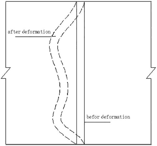
FIGURE 1. Deformation and distortion failure of steels (Schematic diagram).
2.2 Fracture failure of steel nodes
The connection point of steel was weakly stressed and is damaged first under the surrounding rock pressure, causing fracture failure of nodes as shown in Figure 2.
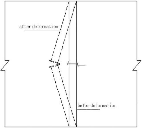
FIGURE 2. Fracture failure of steel nodes (Schematic diagram).
2.3 Plastic bulge of the initial support sidewalls
The pressure distribution of the surrounding rock was not uniform, the pressure of the sidewall was locally concentrated, and the local part of the sidewall bulges out inward as shown in Figure 3.
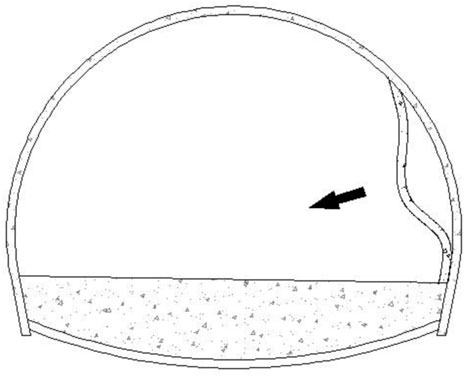
FIGURE 3. Plastic bulge of the initial support sidewall (Schematic diagram).
2.4 Plastic-squeezing failure of the upper bench of the initial support
The bearing capacity of the support structure was insufficient, resulting in the circumferential crack penetration of the initial support shotcrete and the overall inward extrusion and deformation of the support structure as shown in Figure 4.
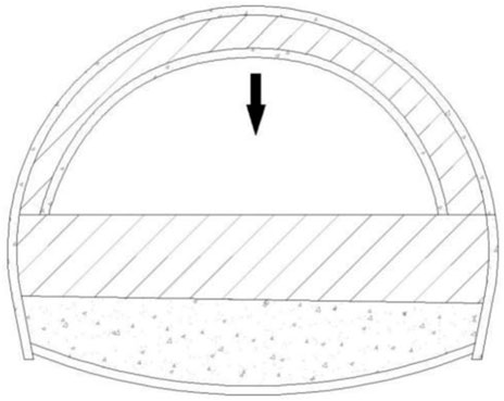
FIGURE 4. Plastic-squeezing failure of the initial support (Schematic diagram).
2.5 Collapse failure of the initial support
Due to the excessive pressure of the surrounding rock, the bearing capacity of the initial support was insufficient, which led to the instability of the support structure and surrounding rock, thus causing collapse failure as shown in Figure 5.
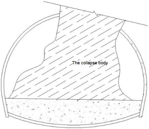
FIGURE 5. Collapse failure of the initial support (Schematic diagram).
2.6 The failure of inverted arch floor heave
Due to the excessive pressure of the surrounding rock and weak surrounding rock base, the mode of inverted arch floor heave was easy to produce in the case of no initial support for the inverted arch as shown in Figure 6.
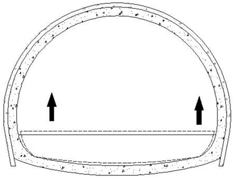
FIGURE 6. Failure of inverted arch floor heave (Schematic diagram).
In combination with the above analysis of the deformation and failure mode of the large deformation of the surrounding rock during tunnel construction and the squeezing deformation that occurred in the Jiangluling Carbonaceous Shale Tunnel project, the large deformation of carbonaceous shale tunnels was found to be characterized by typical soft rock squeezing deformation. In this paper, the mechanical mechanism of large squeezing deformation in Jiangluling Carbonaceous Shale Tunnel was analyzed from the following aspects.
2.7 Crumpled texture of highly compacted carbonaceous shale is the internal cause of large deformation
Fragmentized, straticulate carbonaceous shale is compressed into a compacted body by tectonic extrusion and formed into a crumpled texture by geological movement. After this type of surrounding rock is exposed by tunneling, each bedding is considered as a separate body. Since the highly compacted carbonaceous shale around the excavation contour has a free face to restore its original shape, the swelling effect along the vertical bedding direction is formed, thus releasing the stress formed by the squeezing of the deeply buried strata. The stress releases in the deeply buried carbonaceous shale bedding is shown in Figure 7. According to the field observation of tunnel excavation and support of this type of surrounding rock, the swelling effect of highly compacted carbonaceous shale to restore its original state makes the tunnel excavation and support often emerges problems such as floor heave, excavation contour collapse, distortion and fracture of initial support steel support, shotcrete cracking and spalling, causing significant damage to the initial support.
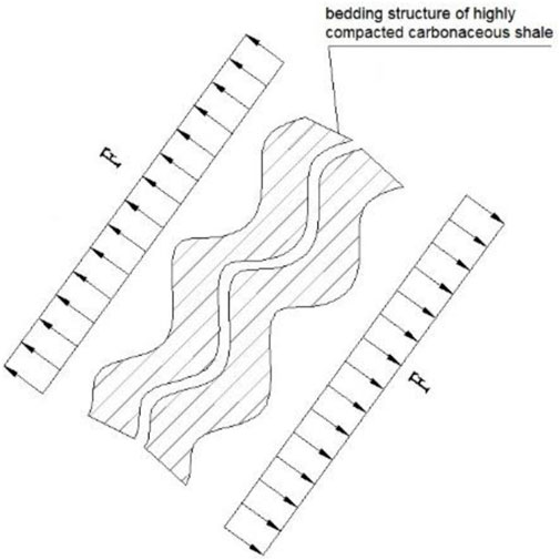
FIGURE 7. The stress release in the deeply buried carbonaceous shale bedding.
This type of surrounding rock gradually decreases in density as the time of exposure to air increases. The swelling effect gradually appears until a loose state is formed.
2.8 Engineering disturbance force is the external cause of large squeezing deformation in carbonaceous shale tunnels
After the tunnel excavation, the original natural stress of the rock mass is destroyed, causing the redistribution of stress and local stress concentration in the surrounding rock. Excavation unloading leads to a sharp decrease in the surrounding pressure of tunnel walls. After excavation, the tangential stress
2.9 Non-linear rheology is the essence of large squeezing deformation in carbonaceous shale tunnels
Under the joint action of initial in situ stress field and engineering disturbance force, the stress level of the surrounding rock of the Jiangluling Tunnel cavern exceeded the lower limit of rock mass rheology, causing extrusive soft rock rheology. The rheological properties of carbonaceous shale are mainly controlled by the structural surface of the surrounding rock bedding. The uniaxial compressive strength of carbonaceous shale is low, and the corresponding lower limit of the rheology of the surrounding rock is also low. The stress concentration generated by excavation and unloading can cause high-speed rheology in the plastic state of squeezing rock, i.e., from extrusion deformation to viscoplastic deformation. Soft rock deformation can be basically divided into elastic, plastic, and rheological stages. The elastic and plastic deformation in soft rocks is less significant, while the rheological deformation occupies the main position.
In addition, after tunnel excavation, viscoplastic deformation leads to strain softening and lower long-term strength value of the rock mass. Stress dilatancy mainly contributes to the large squeezing deformation of carbonaceous shale. Moreover, inadequate support strength and improper construction methods directly cause the large deformation of carbonaceous shale.
In order to further analyzed the failure characteristics and mechanical properties of large deformation in the carbonaceous shale highway tunnel, data monitoring was carried out on two typical cross-sections (ZK330+875, ZK330+897) on site. After analyzing the data, the deformation law of the surrounding rock in the carbonaceous shale tunnel was obtained.
According to Figure 8, 9, the deformation of the surrounding rock after tunnel excavation was basically a linear trend, without an obvious convergence trend. The two-bench construction process on site was developing into a three-bench construction process. After excavation, the upper bench was the first bench deformation, and the deformation pattern is linear with a deformation rate of 3–4 cm; the lower bench was the second bench deformation, and the deformation pattern is also linear with the same deformation rate of 3–4 cm; The application of the inverted arch was the third bench deformation, and the deformation pattern is linear with a reduced deformation rate of <1 cm. The monitoring results showed that the cumulative settlement for 20 days was 40–50 cm. The deformation rate of the surrounding rock at the initial excavation was mainly affected by the gradual release of ground stress at the excavation surface. In the later stage, the release of the surrounding rock stress was completed, and the spatial effect of the excavation operating area disappeared. Tunnel deformation was mainly caused by extrusive surrounding rock rheology. The deformation degree of the tunnel cavern gradually increased with time, presenting a rheological state at a constant speed. In the later stage, if the secondary lining is not applied in time, the rheological deformation of the extrusive surrounding rock will not be controlled effectively.
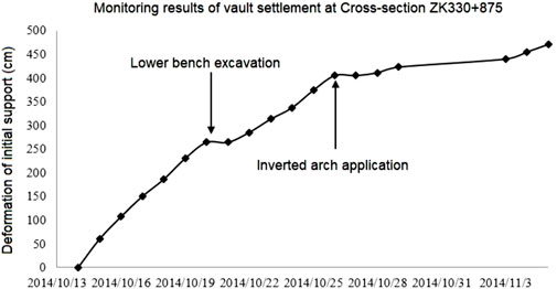
FIGURE 8. The deformation law of the initial support at Cross-section ZK330+875.
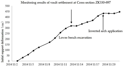
FIGURE 9. The deformation law of the initial support at Cross-section ZK330+897.
In order to analyze the shape of highway tunnel cross-sections and the distribution pattern of surrounding rock deformation, the data of typical cross-sections were extracted, and their deformation maps were drawn, as shown in Figures 10, 11. According to the figures, the deformation of the upper bench after tunnel excavation was large. The deformation of the lower step was relatively small due to the application of the inverted arch. However, the inward deformation of the upper bench was relatively uniform (i.e., the whole surrounding rock is uniformly extruded and deformed inward), with the characteristics of a typical extruded surrounding rock. The measurement results were basically consistent with the actual deformation.
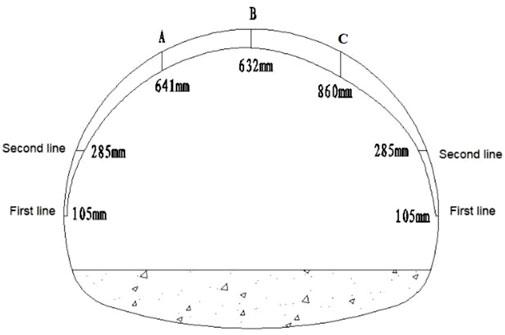
FIGURE 10. Deformation diagram of the surrounding rock at Cross-section YK330+920.
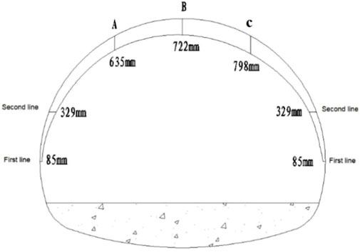
FIGURE 11. Deformation diagram of the surrounding rock at Cross-section ZK330+910.
In order to study the relationship between burial depth and deformation of tunnel surrounding rocks, the data of each monitoring surface in the Jiangluling Tunnel were statistically analyzed. The results showed that there was a relationship between burial depth and deformation of tunnel surrounding rocks. According to Figure 12, the surrounding rock deformation degree of the Jiangluling Tunnel increased with the increasing tunnel burial depth, which is approximately linear. According to linear fitting, when the tunnel burial depth reaches 80 m, the cumulative settlement of the haunch and vault changes abruptly; when the burial depth is between 90 and 100 m, the influence of burial depth on the deformation of the surrounding rock is greater; when the burial depth exceeds 100 m, the cumulative value of the settlement deformation of the tunnel surrounding rock exceeds 30 cm.
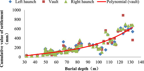
FIGURE 12. Relationship between the vault settlement and burial depth of the left portal of the Jiangluling Tunnel.
According to the deformation of surrounding rock in Jiangluiling Tunnel and the relationship between the deformation and the burial depth of the surrounding rock, the deformation of the surrounding rock of the Jiangluling Tunnel has the typical characteristics of squeezing deformation, fast deformation rate of the surrounding rock, and long duration without convergence.
3 Analysis of the mechanical properties of large deformation of surrounding rocks
By monitoring the interaction law between the surrounding rock and the support structure of the Jiangluling Tunnel, the interaction law between the surrounding rock and the support structure of carbonaceous shale tunnels can be better mastered. Figure 13 showed the laws of initial support surrounding rock pressure with time and excavation process; Figure 14 displayed the law of secondary lining and initial support contact pressure with time and excavation process. As shown in the figure, carbonaceous shale in Jiangluling had obvious rheological characteristics, and the surrounding rock, the initial support effect, and the construction process were related.
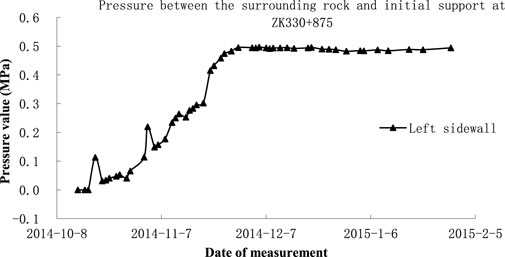
FIGURE 13. The law of the surrounding rock pressure on the left sidewall with time at Cross-section ZK330+875.
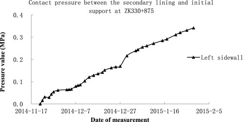
FIGURE 14. The law of left sidewall initial support and secondary lining contact pressure with time at Cross-section ZK330+875.
In Figure 13, the surrounding rock pressure on the left sidewall of the cross-section gradually increased to 0.5 MPa with time and then stabilized. At the initial stage of excavation, the surrounding rock pressure of initial support gradually increased with time, with significant time-space effects. After pouring the inverted arch, the tunnel surrounding rock pressure was redistributed and appeared a decline followed by a rise. The pouring of the secondary lining shared part of the surrounding rock pressure, and the surrounding rock pressure of initial support increased slowly and tends to stabilize. As shown in Figure 14, the contact pressure between the initial support of the left sidewall of the cross-section and the secondary lining grew gradually. The secondary lining was applied on 17 November 2014. At the initial stage of the secondary lining application, the extrusion deformation was suppressed, and the contact pressure increased faster. However, after 78 days of continuous measurements, the secondary lining contact pressure kept growing linearly without a tendency to converge. According to the construction situation on site, it can be seen that the later secondary lining appeared cracking and inverted arch floor heave, and the support structure failed.
In order to analyze the distribution of internal surrounding rock deformation, data were analyzed by multipoint displacement meter method to obtain the thickness range of the broken rock zone of the surrounding rock. The application of the multipoint displacement meter can measure the change of rock displacement at different depths inside the surrounding rock. According to the curve of the displacement amount with time tested by the displacement meter, the convergence of the rock at different depths in the surrounding rock towards the tunnel can be obtained. The large change in displacement with time indicates that the rock mass at that point was fractured. Therefore, according to the magnitude of the change in displacement with time at different points, the broken rock zone and the slightly disturbed zone can be found. (See Figure 15).
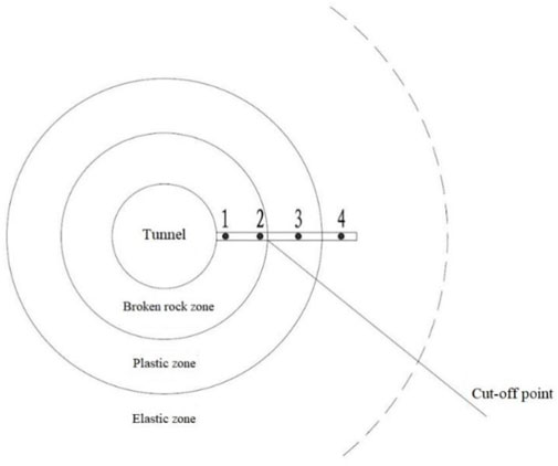
FIGURE 15. Testing principle of multipoint displacement meter method.
The field test results are shown in Figure 16, 17.
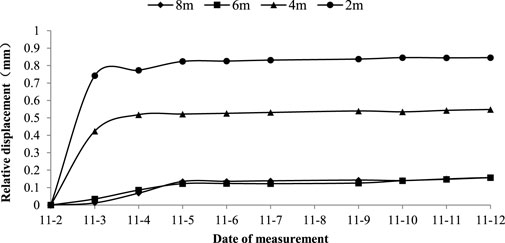
FIGURE 16. The test results of Measuring point 1 at Cross-section ZK331+625 by multipoint displacement meter method.
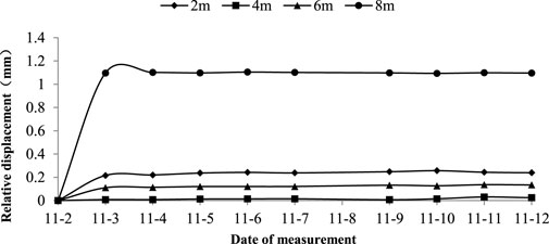
FIGURE 17. The test results of Measuring point 1 at Cross-section ZK331+625 by multipoint displacement meter method.
According to Figure 16, 17, the deformation of the surrounding rock at different depths showed a similar pattern, all showing linear growth and gradually stabilizing at the initial stage of deformation. The deep displacement extent of the surrounding rock decreased with increasing depth. However, the axial displacement extent of four measuring points (2 m, 4 m, 6 m, and 8 m) inside the surrounding rock after tunnel excavation was small compared with that of the surrounding rock free face. Monitoring data showed that the surrounding rock deformation reached 60–80 cm after tunnel excavation. After tunnel excavation, the relative displacement between the surrounding rock and the surface within 8 m around the tunnel was close to 0. That is, the surrounding rock within 8 m around the tunnel was shrinking inward at the same time, thus indicating that the radius of the plastic zone of the Jiangluling Carbonaceous Shale Tunnel was larger than 8 m.
Measuring points 1 and 4 were tested by the acoustic method for the field test. The acoustic method was used to determine the extent to which the surrounding rock was affected by the excavation and the size of the broken rock zone by analyzing the variation of the propagation velocity of the acoustic wave in the surrounding rock at different depths behind the initial support. Since the results of the left and right side tests were symmetrical and relatively similar, the results of one-sided tests were shown below. Typical cross-section test results were shown in Figure 18.
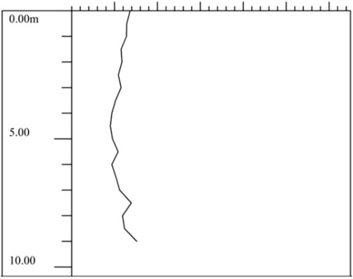
FIGURE 18. Test results of acoustic method at Cross-section YK330+855.
The actual depth of the borehole is 9.5 m in the field test. As shown in Figure 18, the wave velocity difference of sound wave propagation in the surrounding rock within the depth of the measuring point (9.5 m) was small, less than 1.5 km/s. The sound velocity did not have a large abrupt change. It was indicated that the rock mass within 9.5 m around the tunnel was relatively homogeneous after tunnel excavation without abrupt change, which was basically consistent with the lithology of the free face.
4 Analysis of the effect of tunnel burial depth on the large deformation of the surrounding rock
According to the statistical analysis of the monitoring data of each monitoring surface of Jiangluling Tunnel above, the extent of large deformation increases with the increase of tunnel burial depth, indicating that the tunnel burial depth is the main influencing factor for the large deformation of the carbonaceous shale tunnel. In order to further analyze the effect of tunnel burial depth on the large deformation of surrounding rocks, the large deformation of carbonaceous shale tunnels under different burial depth conditions was quantitatively analyzed using FLAC3D software. In the process of simulation, the rock mass adopted the solid element, Mohr-Column model is selected for the simulation. The shell element is used for the initial support, the solid element was used for the secondary lining, and the elastic model was selected for the simulation. Elastic modulus of the initial support is 23GPa, Poisson’s ratioμ is 0.2. Elastic modulus of the secondary support is 33.5GPa, Poisson’s ratioμ is 0.2.The calculation parameters of surrounding rock are shown in Table 1.
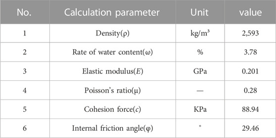
TABLE 1. Calculation parameters of surrounding rock in the numerical model.
The burial depth of the tunnel can be selected based on the following equation in turn.
Where,
Through data analysis, the vault settlement of the carbonaceous shale tunnel and the deformation of peripheral convergence at different burial depths were shown in Table 2.
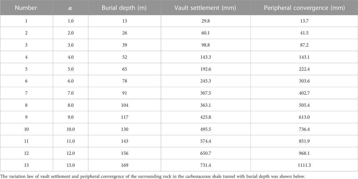
TABLE 2. Calculation results of vault settlement and peripheral convergence of the surrounding rock at different burial depths.
As shown in Figure 19, the values of tunnel vault settlement and peripheral convergence increased with increasing burial depth. Moreover, the growth rate of the peripheral convergence was faster than that of the vault settlement. When the tunnel burial depth was less than 52 m, the cumulative value of tunnel vault settlement was larger than that of peripheral convergence. When the tunnel burial depth was more than 52 m, the cumulative value of peripheral convergence was larger than that of vault settlement. In other words, the horizontal convergence of the carbonaceous shale tunnel was more severe than the vault settlement under burial depth conditions.
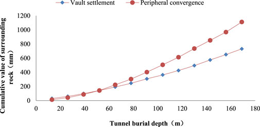
FIGURE 19. Variation of the deformation of tunnel surrounding rock with burial depth.
5 Analysis of the 3D time-space effect of carbonaceous shale tunnel deformation
Before tunnel excavation, the rock mass is in a tri-axial situ stress environment and is in a stable equilibrium state. After excavation, the original natural stress state of the rock mass is destroyed, causing the redistribution of the surrounding rock stress. A part of the insitu stress is released in the form of deformation energy. The other part is transferred to the deeper surrounding rock, and stress redistribution and local stress concentration occur. Stress is constantly adjusted to reach a new equilibrium state that is compatible with the current environment. The engineering disturbance force is the external cause of the large squeezing deformation of carbonaceous shale tunnels. In combination with the construction of the Jiangluling Tunnel, the two-bench with reserved core soil method (Upper bench excavation-Initial support of upper bench- Lower bench excavation-Initial support of lower bench- Inverted arch application- Secondary lining application) was adopted for site construction. A three-dimensional (3D) numerical analysis model was established to analyze the 3D space-time effect of the carbonaceous shale tunnel. The numerical calculation of the 3D model was in a size of 200 (length) * 200 (width) * 90 (depth), as shown in Figure 20.
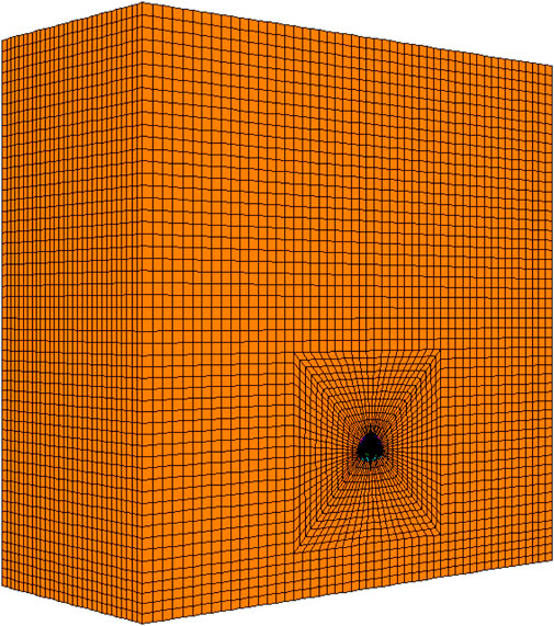
FIGURE 20. Schematic diagram of the overall 3D model.
Deformation of the surrounding rock at Cross-section K0+045 was extracted for analysis. The deformation of the surrounding rock at different excavation steps was shown in Table 3.
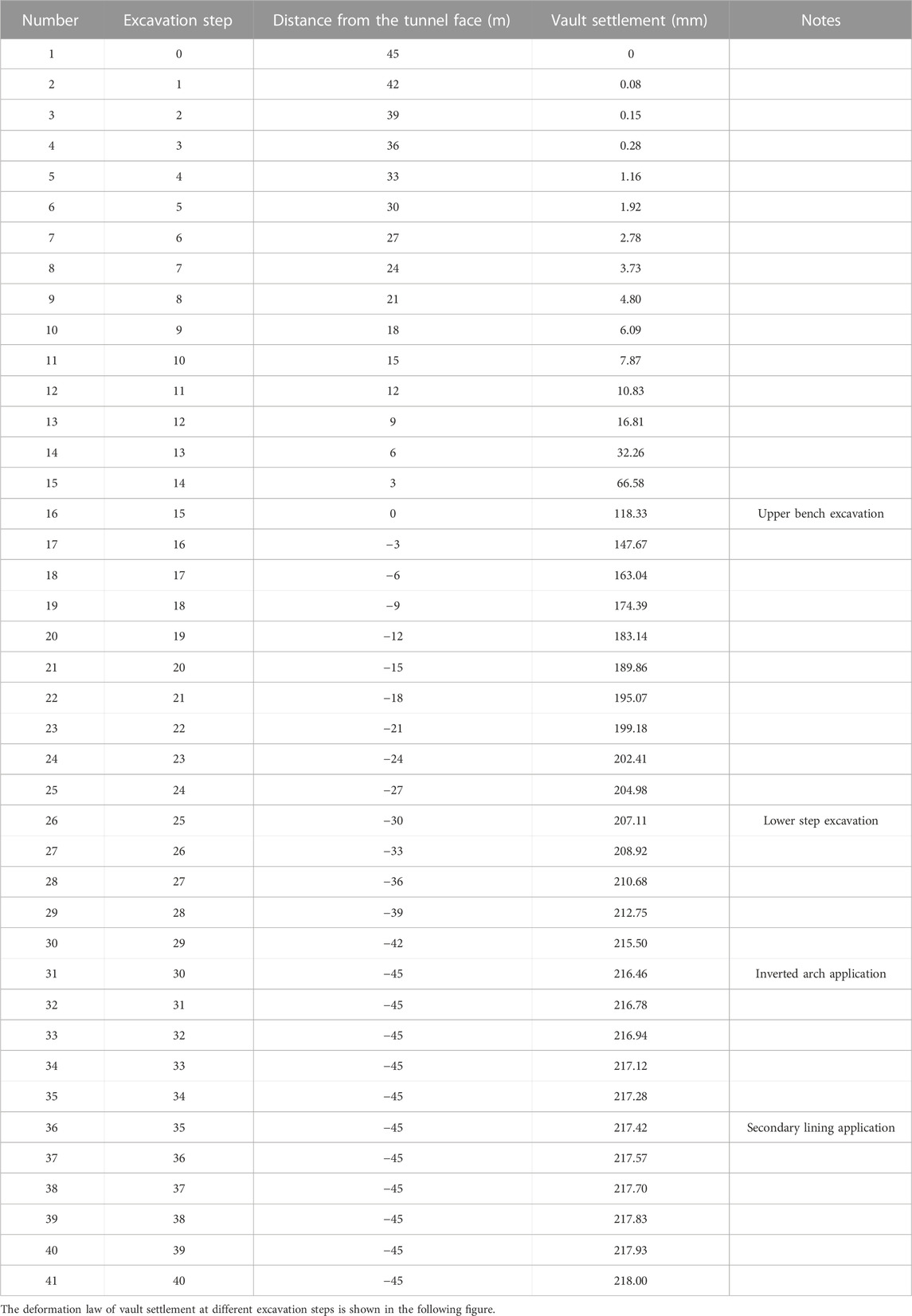
TABLE 3. Calculation results of surrounding rock deformation at different excavation steps.
According to the calculation results, due to engineering disturbance, the deformation curve of the construction cavern of the carbonaceous shale tunnel was typically composed of three parts: deformation before tunnel face excavation, tunnel face deformation, and tunnel face rear deformation. As shown in Figure 21, before tunnel face excavation, the advanced displacement of surrounding rock was 6.7 cm; after the secondary lining operation, the cumulative displacement of the surrounding rock was 21.8 cm. The advance displacement accounted for 30.73% of the total displacement. Advance displacement occurred within 30 m in front of the tunnel face, and the advance displacement was more significant within 10–15 m (1D-2D) in front of the tunnel face. As exhibited in Figure, the influence of the plastic zone of the surrounding rock after tunnel face excavation also extended to the range of 15 m in front of the tunnel face, which was consistent with the calculation results of advance displacement. In other words, the influence range of the advanced displacement in front of the tunnel face of the carbonaceous shale tunnel was 1–1.2 span. Therefore, it is of great significance to strengthen advanced support to control the surrounding rock deformation during the construction of carbonaceous shale tunnels in Figure 22. With the excavation of the tunnel face, the deformation rate of the surrounding rock gradually decreased. When the tunnel face was dug to 3-4D, the influence of the spatial effect of the excavation of the tunnel face stratum basically disappeared. This pattern shows the time-space effect of carbonaceous shale tunnel construction.
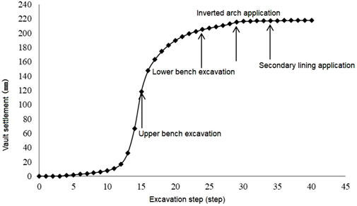
FIGURE 21. Variation pattern of the vault settlement of the surrounding rock with tunnel excavation steps.
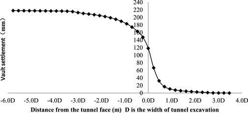
FIGURE 22. Variation pattern of the vault settlement of the surrounding rock with distance from the tunnel face.
6 Conclusion
In this paper, the large deformation characteristics of the Jiangluling Tunnel were analyzed to explore the deformation law of the carbonaceous shale tunnel. Additionally, with the combination of the monitoring data analysis, theoretical analysis, and numerical simulation analysis, the large deformation mechanism of the carbonaceous shale tunnel were analyzed to provide a theoretical basis for the design and construction. The analysis of this paper led to the following conclusions.
1) During the construction of Jiangluling Carbonaceous Shale Tunnel, the support structure can produce the following six failure modes due to large deformation of the surrounding rock: ① Distortion failure of initial support steels; ② Fracture failure of steel nodes; ③ Plastic bulge of initial support sidewalls; ④ Plastic-squeezing failure of the initial support upper bench; ⑤ Collapse failure of initial support; ⑥ Failure of inverted arch floor heave.
2) The causes of large deformation during construction can be divided into internal and external causes. Internal factors are as follows: Crumpled texture of deeply buried and highly compacted carbonaceous shale bedding, low rock strength index, high plastic strain, and large plastic zone range. External factors are as follows: The tunnel excavation cross-section is large, the construction method is not suitable, and the support parameters and support measures are not appropriate.
3) The deformation extent of the surrounding rock of Jiangluling Carbonaceous Shale Tunnel increases with the increased burial depth in an approximately linear manner. Moreover, the rate of peripheral convergence grows faster than that of the vault settlement. When the tunnel burial depth is less than 52 m, the cumulative value of tunnel vault settlement is larger than that of peripheral convergence. In contrast, when the tunnel burial depth is more than 52 m, the cumulative value of peripheral convergence is larger than that of vault settlement. In other words, the horizontal convergence of the carbonaceous shale tunnel is more severe than the vault settlement under burial depth conditions.
4) The deformation curve of the construction cavern of Jiangluling Carbonaceous Shale Tunnel typically includes the advanced displacement before tunnel face excavation, tunnel face deformation, and deformation behind tunnel face. The advance displacement accounts for 30.73% of the total displacement. The influence range of advance displacement is 1-1.2D in front of the tunnel face. The surrounding rock deformation caused by the excavation of the tunnel face arriving specific stratum does not reach the maximum value. With the excavation of the tunnel face, the deformation rate of the surrounding rock gradually decreases. When the tunnel face is dug to 3-4D, the influence of the spatial effect of the excavation of the tunnel face stratum basically disappears.
Data availability statement
The original contributions presented in the study are included in the article/supplementary material, further inquiries can be directed to the corresponding authors.
Author contributions
PC performed the data analyses and wrote the manuscript; XH contributed to the conception of the study; EL helped perform the analysis with constructive discussions; HG performed the experiment.
Funding
The authors appreciate the funding of the program of National Research and Development Program of China (2021YFC13002000).
Conflict of interest
PC, XH, and HG were employed by China Merchants Chongqing Communication Research & Design Institute Co. Ltd., and National Engineering Research Center of Road Tunnel Ltd.
The remaining author declares that the research was conducted in the absence of any commercial or financial relationships that could be construed as a potential conflict of interest.
Publisher’s note
All claims expressed in this article are solely those of the authors and do not necessarily represent those of their affiliated organizations, or those of the publisher, the editors and the reviewers. Any product that may be evaluated in this article, or claim that may be made by its manufacturer, is not guaranteed or endorsed by the publisher.
References
Bian, K., Liu, J., Liu, Z., Liu, S., Ai, F., Zheng, X., et al. (2017). Mechanisms of large deformation in soft rock tunnels: A case study of huangjiazhai tunnel. Bull. Eng. Geol. Environ. 78, 431–444. doi:10.1007/s10064-017-1155-8
Ding, X., Weng, Y., Zhang, Y., Xu, T., Wang, T., Rao, Z., et al. (2017). Stability of large parallel tunnels excavated in weak rocks: A case study. Rock Mech. Rock Eng. 50, 2443–2464. doi:10.1007/s00603-017-1247-6
Duan, B., and Weng, X. (2012). Research on the surrounding rock deformation law of carbon shale small interval tunnel. Constr. Technol. 41 (19), 87–89.
Gao, L., Zhang, F., Li, X., and Yang, C. (2005). Analysis of the characteristics and mechanism of large deformation in Muzhailing Tunnel. Chin. J. Rock Mech. Eng. 22, 5521–5526.
Gao, S., Chen, J., Zuo, C., Wang, W., and Sun, Y. (2016). Structure optimization for the support system in soft rock tunnel based on numerical analysis and field monitoring. Geotechnical Geol. Eng. 34, 1089–1099. doi:10.1007/s10706-016-0029-3
GuoLi, H., Liu, K., Cui, X., and Luo, H. (2019). Study on bolt support design for carbonaceous shale tunnel of highway at high altitude and cold region. IOP Conf. Ser. Earth Environ. Sci. 304 (3), 032013. doi:10.1088/1755-1315/304/3/032013
Sun, J., and Ling, J. M. (1995). “Time and space effects of damage and failure of rock mass[A],” in Proc. 8th int. Congr. On rock mech. (Tokyo: ISRM), 193–196.
Tan, Z., Li, S., Wang, J., and Yang, Y. (2021). Experimental study on large deformation characteristics of soft surrounding rocks in Zhonglao Railroad Tunnel. China Railw. Sci. 42 (04), 98–106. doi:10.3969/j.issn.1001-4632.2021.04.12
Tang, S. B., and Tang, C. A. (2012). Numerical studies on tunnel floor heave in swelling ground under humid conditions. Int. J. Rock Mech. Min. Sci. 55 (6), 139–150. doi:10.1016/j.ijrmms.2012.07.007
Teng, J., and Tang, J. (2017). Analysis of the mechanism of floor heave in layered carbonaceous shale tunnels. J. Railw. Sci. Eng. 14 (01), 110–116. doi:10.3969/j.issn.1672-7029.2017.01.017
Tian, S. (2013). Deformation and damage mechanism of high in situ stress carbonaceous shale in Baozhen Tunnel. J. Beijing Jiaot. Univ. 37 (01), 21–26. doi:10.11860/j.issn.1673-0291.2013.01.004
Wang, S. (2010). Study on large deformation control technology of tunnel soft surrounding rock in complex in situ stress areas. Beijing: Jiaotong University.
Xie, J., and Chen, J. (2007). Analysis of the characteristics and mechanism of large deformation of soft surrounding rocks in Huocheling Tunnel[J]. J. Wuhan Univ. Sci. Technol. Nat. Sci. Ed. 20, 647–651. doi:10.3969/j.issn.1674-3644.2007.06.025
Yang, Q. (2016). Study on the deformation characteristics of the surrounding rocks and construction plan for the Jiangluling Carbonaceous Shale Tunnel. Xi'an, China: Chang’an University.
Zhang, Z., and Guan, B. (2000). Study on the deformation law of soft surrounding rock tunnel under in situ stress conditions. Chin. J. Geotechnical Eng. 25, 696–700. doi:10.3321/j.issn:1000-4548.2000.06.013
Keywords: Carbonaceous Shale Tunnels, large deformation, mechanical properties, numerical simulation, tunnel construction
Citation: Cao P, Hu X, Liu E and Guo H (2023) Mechanical properties and numerical simulation analysis on large deformation of Jiangluling Carbonaceous Shale Tunnel. Front. Earth Sci. 11:1125410. doi: 10.3389/feart.2023.1125410
Received: 16 December 2022; Accepted: 17 February 2023;
Published: 04 April 2023.
Edited by:
Chun Zhu, Hohai University, ChinaReviewed by:
Bin Gong, Shandong University of Science and Technology, ChinaCheng Zhao, Tongji University, China
Dongming Zhang, Chongqing University, China
Zhenkun Hou, Guangdong University of Technology, China
Copyright © 2023 Cao, Hu, Liu and Guo. This is an open-access article distributed under the terms of the Creative Commons Attribution License (CC BY). The use, distribution or reproduction in other forums is permitted, provided the original author(s) and the copyright owner(s) are credited and that the original publication in this journal is cited, in accordance with accepted academic practice. No use, distribution or reproduction is permitted which does not comply with these terms.
*Correspondence: Peng Cao, Y2FvcGVuZzFAY21oay5jb20=; Xuebing Hu, aHV4dWViaW5nQGNtaGsuY29t