 Xiaoyu Wang1,2
 Mingming Zheng
 Qiaomu Qi
- 1School of Civil Engineering, Henan Vocational University of Science and Technology, Zhoukou, China
- 2State Key Laboratory of Geohazard Prevention and Geoenvironment Protection, Chengdu University of Technology, Chengdu, China
- 3Engineering Research Center of Rock-Soil Drilling and Excavation and Protection, Ministry of Education, China University of Geosciences (Wuhan), Wuhan, China
In order to investigate the effect of cement slurry penetration during cementing in gas hydrate-bearing sediments. In this study, gas hydrate bearing sediments in Shenhu Area of the South China Sea is taken as the research object, numerical simulation software TOUGH+HYDRATE is used to realistically reproduce the process of cement slurry exothermic and penetration by “continuous segmental simulation.” The physical properties response of sediments near the well wall during cementing under different cementing process parameters and sediment geological parameters are well studied. Results show that the hydration exothermic rate of cement slurry has significant influence on the decomposition degree of hydrate in the penetration area, when it is higher than 0.21 J·(g·s)−1, the hydrate in the penetration range is completely decomposed. The cementing pressure difference affects the cement slurry penetration depth, the extent of sediment pressurization and heat-up, which in turn affects the range of the decomposition zones. In addition, it is helpful to increase pore pressure and hydrate phase equilibrium, but it should be strictly controlled within the window of sediment fracture pressure. Extending the holding time of cementing pressure difference expands the heat-up and decomposition zones, but also delays the onset of hydrate decomposition. Higher saturation prevents the penetration of cement slurry and weakens the diffusion of pore pressure, which causes the shrinkage of the heat-up and decomposition zones, and makes higher pressure in the decomposition zone. The hydrate phase equilibrium environment directly determines the resistance of hydrate sediments to perturbation, with insignificant changes in physical properties in stable sediments. The permeability affects the transport efficiency of pore fluid and expands the heat-up zone and decomposition zone, but also weakens the pore pressure peak of sediment, the increase of permeability from 1 to 100 mD expands the decomposition zone from 1 to 10 cm. The porosity has a less significant effects on the extent of sediment physical properties. This study is a valuable guide and reference for hydrate sediment cementing operations.
1 Introduction
With the gradual depletion of continental oil-gas resources and the maturity of marine oil-gas development technology, marine areas have become the most desirable resource replacement areas for some countries (Wang J. Q., 2021). In China, the South China Sea region has been proven to contain large amounts of oil-gas resources and natural gas hydrate resources, which are predicted to reach a total of 29 billion tons of oil and gas (Lu, 2013). Due to the characteristics of the marine sedimentary environment, most marine oil, gas and hydrate resources are located in the marine basin area (Zhang et al., 2009; Pang, 2012), which has a high overlap with the geographic location of oil-gas resources and gas hydrate resources in the South China Sea (Figure 1) (Sun et al., 2011; Weng et al., 2013; Wang D. D., 2021). Since hydrates can only exist stably in low-temperature and high-pressure environments (Sloan and Koh, 2008), they are generally located in the shallow surface area of the seafloor, while oil-gas resources are usually buried at depths of several kilometers. Therefore, during the drilling of oil-gas wells, gas hydrate bearing sediments (GHBS) are often encountered in the shallow surface layer.
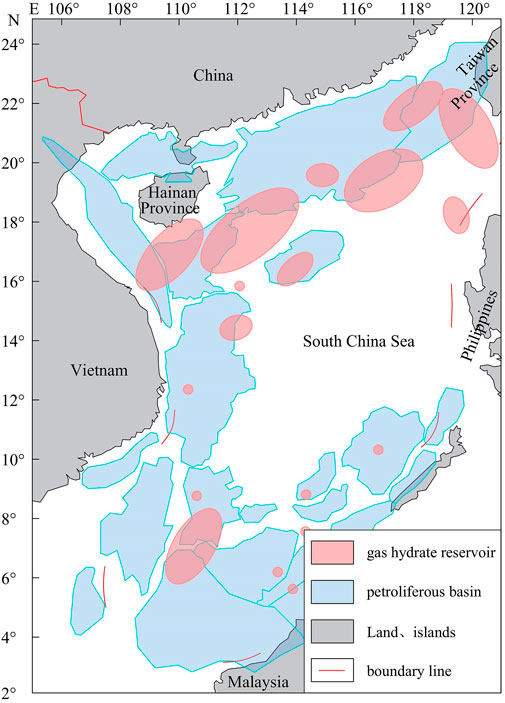
FIGURE 1. Distribution of hydrocarbon-bearing basins and gas hydrate reservoirs in the South China Sea (adapted from Wang D. D., 2021; Weng et al., 2013; Sun et al., 2011).
In the Shenhu Area of the South China Sea, the GHBS are complex, mainly powdery sands and clays, and the mechanical strength is low in the sediments. The hydrate reservoir environment is close to its phase equilibrium, so slight changes in temperature and pressure can lead to its decomposition (Ning et al., 2010). In deepwater drilling, the entire well is usually cemented, and the cement hydration exotherm during cementing will inevitably cause the sediment to heat up, which will cause the decomposition of the hydrate near the wellbore wall and reduce the density of the sediment. Meanwhile, the high-pressure free gas and water generated by decomposition can further disturb the stability of GHBS and even cause sediment rupture, which will seriously affect the quality of cementing. Therefore, it is crucial to investigate the effect of the cementing process on GHBS, which will provide a theoretical basis for the design and optimization of the cementing process to ensure the safety of the wellbore.
To address the cementing problem of GHBS, Li. (2018) established a calculation method for the cement slurry penetration distance and penetration volume in the sediments around a well and studied the effect of cement slurry penetration into GHBS by using indoor tests and numerical simulations together. The results showed that it would lead to wellbore wall destabilization and affect the quality of cementing under the effect of cement slurry penetration. Yang et al. (2022) developed a phase change microencapsulated low-heat cement slurry. It was shown that the thermal adjustment of the microencapsulation suppressed the heat-up rate of the cement slurry and significantly reduced the damage to hydrates. Xu et al. (2014) proposed a silicate cement slurry system for use in GHBS environments to address the problems of low temperatures, fragile sediments, and gas hydrate intercalation in cementing wells for deepwater drilling. Xi et al. (2020) developed a cement slurry for cementing GHBS in the sea at temperatures ranging from 4°C to 30°C. The above scholars have mainly studied the optimization of cementing process, but the effect of cement slurry penetration on GHBS has not been systematically investigated.
Cement slurry penetration into sediments is essentially a mass and heat transfer process, which is very similar to that of drilling fluids, and the drilling process of GHBS has been studied for quite a long time. Zheng et al. (2022, Zheng et al. (2021), Zheng et al. (2020), Zheng et al. (2017) conducted a large space-scale indoor simulation experiment for the process of drilling fluid penetration into GHBS using an artificial rock core preparation device and an integrated simulation system for seepage and exploitation in GHBS. The study demonstrated the physical property response rule of sediments in this process and noted that temperature is the most important influencing factor of hydrate decomposition. Then, TOUGH+HYDRATE was used to conduct a preliminary numerical simulation of cement slurry penetration into GHBS and to obtain the physical property response of the sediment in this process. Tinku and Vikas. (2018) analyzed the effect of hydrate inhibitors in subsea GHBS on the rheological behavior of drilling fluids and optimized drilling fluid formulations. Zhang et al. (2018) used ultrasonic testing to investigate the process of two types of hydrate thermodynamic inhibitor drilling fluids, specifically NaCl and ethylene glycol, penetrating into GHBS, which explored the effect rule of hydrate thermodynamic inhibitors on hydrate decomposition. Merey (2019) evaluated and analyzed follow-up logging and other drilling data from gas hydrate drilling campaigns around the world, finding that the risks in drilling are more manageable and concluding that the key to drilling safety is proper wellbore design. Ning et al. (2013) used TOUGH+HYDRATE numerical simulation software to observe the dynamic behavior of drilling fluid penetration into GHBS, which proved that heat transfer phenomena caused by temperature differences between drilling fluid and sediment can lead to hydrate decomposition and thus affect sediment stability, followed by a systematic study of the sensitivity of sediment properties and drilling process parameters. Tu et al. (2010) studied the decomposition of hydrates in the pores of porous media, thus identifying the main influencing factors in this process, and finally proposed a new model of drilling fluid penetration. The above studies have well revealed the effect of drilling fluid penetration on GHBS, and the results are important references for this study due to the similarity of the two scenarios.
The above studies are a guide to analyze the physical property response rules of GHBS during cementing, but the unique difficulty in the cementing problem is that the cement slurry not only continuously penetrates GHBS during cementing but is also continuously exothermic as a new heat source, making the process more variable and significantly more complex. Based on this, the authors take the SH2 station exploration well in the hydrate drilling project GMGS-1 in the Shenhu Area of the South China Sea as the research object, using the numerical simulation software TOUGH+HYDRATE developed by Lawrence Berkeley National Laboratory to simulate the penetration process of the cement slurry as a dynamic exothermic source into the sediment during the cementing process. Then, we study the influence of the cementing process on the physical properties of GHBS near the wellbore wall under in situ sediment conditions and cementing process conditions. Furthermore, we analyze the influence of different cementing process parameters and sediment properties on this process to provide some guidance and reference for GHBS cementing operations.
2 Simulation methods
2.1 Simulation objects
Due to the superiority of the reservoir conditions, hydrate reservoirs in the Shenhu Area in the middle part of the northern land slope of the South China Sea have become a popular research area for hydrate exploration and development (Wu et al., 2007b; Wang et al., 2011a, 2011b; Yang et al., 2017; Li et al., 2022). In 2007, China conducted a gas hydrate drilling project GMGS-1 in this area, and the location of the study area in this study is shown in Figure 2. The drilling project drilled eight scientific drilling holes (SH1∼SH8), and satisfactory test hydrate samples were recovered from three holes, SH2, SH3, and SH7 (Wu et al., 2007a; Zhang et al., 2007). In particular, the SH2 hole is extremely rich in both field data and sediment data, so it is an important object for research on hydrates. For example, Zhu et al. (2020) used these hole data to predict the accumulation of gas hydrates in marine sediments. Sun (2018) used these data to simulate and analyze the influence pattern of the drilling construction process on GHBS. Shen et al. (2019) used it to build a model to quantitatively explain the source of gas production in extraction wells.
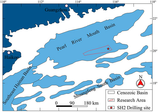
FIGURE 2. Location map of the GMGS-1 project in the Shenhu Area of the South China Sea (adapted from Wu et al., 2007b).
This study also relies on field data from the SH2 of the GMGS-1 project for the simulation study. Based on logging data and sample analysis results (Nakai et al., 2007; Wang et al., 2011a, Wang et al., 2011b), the water depth at this site is approximately 1,235 m. The hydrate reservoir is stored in the sediment from approximately 185–229 m below the seafloor, and the longitudinal depth of the sediment is approximately 44 m. The sediment mainly consists of powdery clay with a porosity of approximately 0.40. In situ logging data indicate that the seafloor temperature is approximately 4°C. The hydrate saturation is high, up to 0.47. The geothermal gradient is approximately 47°C/km.
2.2 Numerical model and parameters
The cement slurry penetration process in cementing is shown in Figure 3, based on which a numerical model is developed. Since cement slurry penetration is radially dispersed from the wellbore to the surrounding area, the two-dimensional cylindrical coordinate system is the most suitable to describe the process. In addition, the cementation process is usually homogeneous in long sections of sediments, and the GHBS can be considered homogeneous within a certain range, so the penetration process can be assumed to be homogeneous in any section in the direction of the wellbore axis. Therefore, this three-dimensional model can be reduced to a one-dimensional problem in a two-dimensional coordinate system. As shown in Figure 4, a thin layer of 0.1 m thickness in the GHBS is taken as the object of study, which is used to establish the numerical model. The model is an axisymmetric cylinder of 0.1 m thick, the wellbore is at the center, the diameter of the wellbore is taken as 280 mm, the steel casing of 240 mm outer diameter and 10 mm thickness is chosen, and the annular space between the outer wall of the casing and the sediment is 20 mm thick. Outside the wellbore is the GHBS. Combined with previous studies on related issues (Liu, 2018; Sun, 2018), the radial depth was taken as 5 m for a conservative estimate. The mesh is divided into one layer in the axial direction of the wellbore, with a thickness of 0.1 m. The mesh is divided into 113 cells in the radial direction, which are dense near the wellbore wall and sparse at the far side. The cell closest to the center is the casing cell, the outer cell is the annulus cell, and the further outer cells are all GHBS cells.
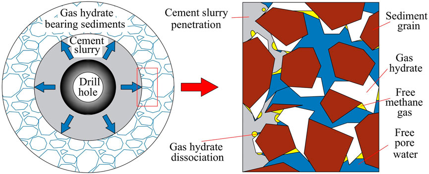
FIGURE 3. Schematic diagram of cement slurry for cementing penetrating into GHBS.
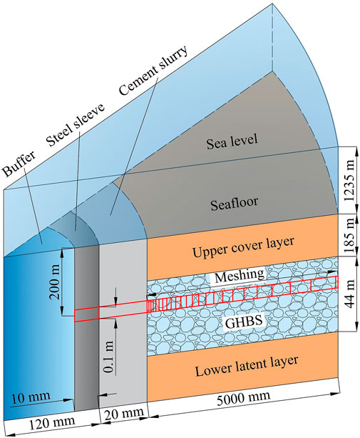
FIGURE 4. Schematic diagram of the wellbore-sediment numerical model for GHBS cementing.
The sediments 200 m below the seafloor were used as the target study layer in the simulation, and the values taken were based on the available logging and drilling coring data from the SH2 station (Wu et al., 2007b; Nakai et al., 2007; Wang et al., 2011a, Wang et al., 2011b). The sediment density is 2,600 kg/m3, the wet thermal conductivity is 3.1 W/(m°C), the dry thermal conductivity is 1.0 W/(m°C), the specific heat of grains is taken as 1,000 J/(kg°C), the sediment compression coefficient is taken as 1.0 × 10⁻⁸ Pa−1, the porosity is taken as 0.4, and the absolute permeability is taken as 1.0 × 10⁻¹⁴ m2. The sediment temperature is 13.4°C, and the pore pressure is 14.5 MPa. The sediment pore water salinity is 3.05%, which is basically the same as that of the overlying seawater. The gas hydrate phase stability temperature in this environment is calculated to be 15.4°C. The pore space is almost filled with hydrate and water, the hydrate saturation is taken as 33%, and the free gas saturation is approximately 1%∼1.2%. To avoid interference, the original gas phase material of the sediment is neglected.
In cementing operations, to ensure the cementing strength and sealing performance of the second interface, the annular cement slurry is usually kept under pressure in a safety pressure window for a period of time after cement injection so that the cement slurry penetrates into the sediment. During this process, the cement slurry leading edge position and exothermic rate are constantly changing; that is, there is the problem of a “dynamic exothermic source.” To fully recreate this process, “continuous segmental simulation” is used. During the holding pressure phase, the cement slurry cell is set as a constant pressure cell and held for the required time, and at the end of the holding pressure, it is changed to a time-varying cell. The whole process is divided into several segments for simulation (segment length can be freely set according to the accuracy requirements, this paper uses 2 min) until the initial setting of cement slurry, and the initial setting time is taken as 28 min. During the experiment, the amount of cement slurry penetration at the end of each simulation is recorded to determine the distribution range of cement slurry at the beginning of the next simulation, based on which the exothermic cells are set at the corresponding positions in the model. Additionally, according to the measured data, the exothermic rate of hydration is adjusted so that the cement slurry penetration process can be accurately recreated. In addition, the SH2 station well sediments are mostly weakly cemented and uncemented, and the safety pressure window is narrow, so the designed cementing pressure difference needs to be within the range of sediment fracture pressure.
The cementing parameters in the simulation were selected based on the cementing technology schemes of previous studies (Xu et al., 2014; Liu, 2018; Liu et al., 2018; Zhang et al., 2020; Yang et al., 2021a; Yang et al., 2021b). The cementing pressure difference is taken as 1 MPa, and the holding time of cementing pressure difference is taken as 7 min. The cement slurry adopts a low-temperature low-density cement slurry system, and the density is taken as 1,050 kg/m3. The average exothermic rate during the simulation is taken as 0.28 J/(g·s), and its specific segmental values are shown in Table 1. The initial temperature of the cement slurry is usually somewhat higher than the sediment temperature, which is taken as 14.4°C. The parameters required in the simulation are summarized in Table 2.
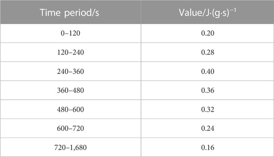
TABLE 1. Segmented values of the cement hydration exothermic rate during simulation.
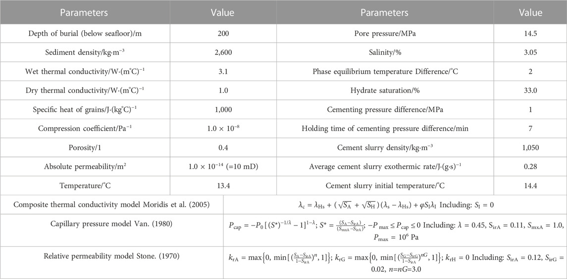
TABLE 2. Main parameter values of the numerical simulation.
3 Main characteristics of the cement slurry penetration into the GHBS process
Figure 5 illustrates the penetration of the cement slurry during the cementing process. It can be seen in the figure that cement slurry penetration into the sediment mainly occurs during the holding pressure phase, which is obviously due to the presence of the cementing pressure differential providing a strong driving force for the penetration process. It can also be seen that the cement slurry penetration is not linear during the pressure-holding period but gradually slows down with time. The reason for this is that the high-pressure fluid penetrating into the sediment in the early stage raises the sediment pore pressure and reduces the pressure difference, making the driving force of the penetration gradually weaker. After the maintenance pressure is removed, the cement slurry penetration comes to a standstill and hardly changes significantly in the subsequent time. Therefore, it can be assumed that cement slurry penetration occurs mainly during the holding pressure period, with a penetration depth of approximately 2.5 cm, after which the penetration is negligible.

FIGURE 5. Variation in cement slurry penetration depth with time.
Figures 6A, B show the distribution of pressure in the sediment at various time points. During the holding pressure period (before 420 s), the pore pressure increased sharply near the wellbore wall, and the leading edge of the pressure increase area gradually moved deeper into the sediment as the holding pressure process continued. This is because the high-pressure fluid (cement slurry) continuously penetrated into the sediment under the pressure differential during the holding pressure, which raised the sediment pore pressure, and the continuous pressurization caused the high-pressure range to spread to the greater depth. After the removal of the cementing pressure differential (after 420 s), the pressure near the wellbore wall first experienced a sharp drop and then continued to slowly decrease with time. However, the high-pressure impact zone gradually penetrated deeper into the sediment and finally reached approximately 2.5 m. This is because the removal of the cementing pressure differential caused the high-pressure fluid accumulated at the wellbore wall to be released instantaneously, resulting in a sharp pressure drop, and then the high-pressure fluid gradually moved deeper due to the pressure differential. There are two points worth noting here: 1) the pressure rose near the wellbore wall after 900 s; 2) the highest pressure point in the sediment was initially at the wellbore but deepened to a distance from the wellbore wall at the later stage. This is due to the decomposition of the hydrate near the wellbore wall at the later stage, which made the pressure rise at the decomposition site and a local pressure peak when the pressure at the decomposition was higher than that at the wellbore wall.
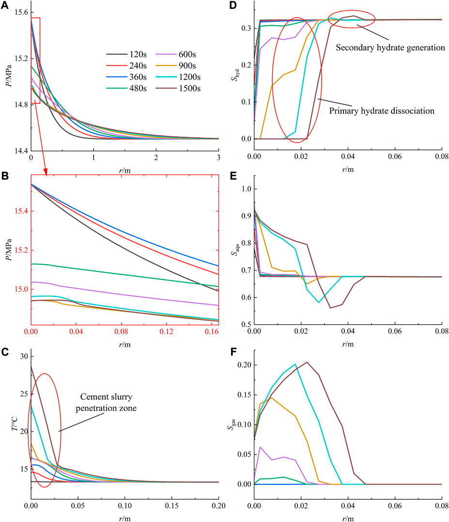
FIGURE 6. Changes in the main physical properties of the sediment at different times during cement slurry penetration. (A) Pressure. (B) Pressure local amplification. (C) Temperature. (D) Hydrate saturation. (E) Liquid saturation. (F) Gas saturation.
Figure 6C shows the distribution of temperature in the sediment at various time points. As seen in the figure, the region of large temperature variation occurs mainly within the cement slurry penetration zone, with the leading edge of the region being approximately 2.5 cm. Before 900 s, the temperature variation in the region is extremely small, after which it starts to increase rapidly. Combined with Figures 6D–F, it is easy to see that this is because when the temperature rises to a certain extent before 900 s, the temperature increase is hindered by the heat absorption due to the decomposition of hydrate in the region, and only after that the hydrate is consumed does the temperature start to rise rapidly. At deeper depths, due to the absence of cement slurry, the temperature increase relies mainly on heat conduction, which changes very little, and the leading edge of the region is approximately 10 cm.
Figures 6D–F show the distribution of hydrate, liquid and gas saturation at various time points. Combined analysis shows that the decomposition behavior of hydrate in the range of cement slurry penetration starts at approximately 480 s, which is due to the time required to warm up the sediment to disrupt the hydrate phase equilibrium environment. After that, the hydrate decomposition deepened in this range, after that, the hydrate decomposition deepened and accelerated in this range, which is because the lower the hydrate saturation, the faster the decomposition rate (Chen et al., 2020). It is noteworthy that the hydrate saturation increased instead in the deep area immediately adjacent to the hydrate decomposition zone. This is because the hydrate decomposition produced high-pressure gas and water and absorbed heat. These high-pressure fluids flowed to both sides under the effect of the pressure difference, which increased the sediment pore pressure immediately adjacent to the decomposition area. In contrast, the warming due to heat conduction is not significant, and together with the heat absorption of hydrate decomposition, led to no significant change in temperature in the zone of pressure increase. This high-pressure and low-temperature environment, together with the methane gas brought by the freshly decomposed hydrate, contributes to the secondary generation of hydrate, forming a high-saturation zone of hydrate at the periphery of the decomposition zone around the well (Figure 7). As the temperature of the decomposition zone gradually increases and the heat conduction slowly spreads, this early formed high saturation zone will decompose again, and a new high saturation zone will be formed at its periphery. The process can be imagined such that when the high saturation zone is formed at the periphery of the decomposition zone, it moves outward with the expansion of the decomposition zone, which is eventually stabilized with the cessation of the exothermic hydration of cement. This is consistent with the conclusion of Yang et al. (2023) that the nucleation and growth of hydrates would preferentially proceed towards a low temperature region. It can also be seen in Figure 6D that the total amount of hydrate generated in 1,200–1,500 s is significantly higher than that in 900–1,200 s for the same time interval. This is because the fluid flow rate is relatively slower at a distance from the wellbore wall, while it is known that lower flow rate promotes hydrate generation according to Sun et al. (2023).
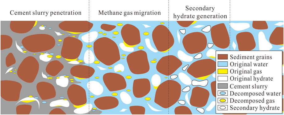
FIGURE 7. Schematic diagram of Secondary hydrate generation.
4 Discussion
During cement slurry penetration, the main characteristic of this process in GHBS compared to conventional hydrocarbon-bearing sediments is that hydrate decomposition and reorganization will occur when cement slurry penetration disrupts the hydrate phase equilibrium. The characteristics of cement slurry penetration in conventional hydrocarbon-bearing sediments are influenced by several factors, such as the depth and extent of penetration controlled by the cementing process and formation properties. Based on the data from station SH2, we further explore the influence of cementing process parameters and sediment properties on the process to clarify the influencing factors of cement slurry penetration in GHBS and then provide guidance for drilling and logging in the field.
4.1 Effect of cementing process parameters on the cement slurry penetration process
4.1.1 Hydration heat of cement slurry
During cementation of GHBS, the hydration exothermic rate of the cement slurry directly determines the exothermic heat of the cement slurry. Figure 8A shows the pressure distribution in the late sediment at different exothermic rates. It is obvious that there is an increase in pore pressure over a large zone in the sediment as the exothermic rate is increased. This is because as the exothermic heat increases, more hydrates are decomposed in the sediment, which generates more methane gas and further raises the pore pressure in the sediment.
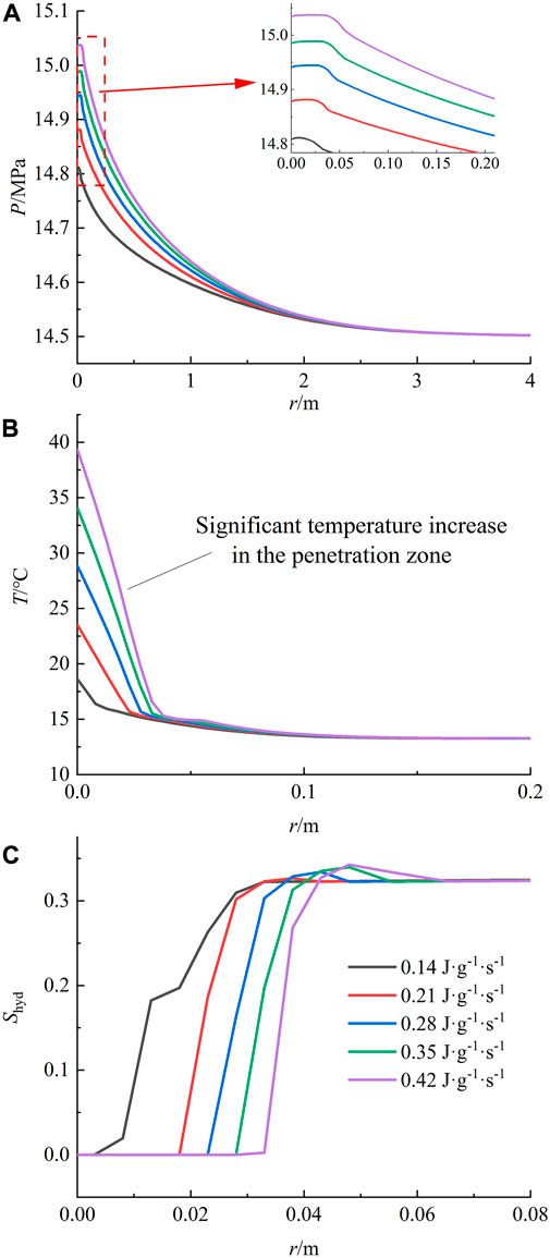
FIGURE 8. Changes in the main physical properties of the sediment around the wellbore at 25 min under different exothermic rates. (A) Pressure. (B) Temperature. (C) Hydrate saturation.
Figure 8B shows the temperature distribution of the sediment after stabilization at the late stage (25 min) under different exothermic rates. As the exothermic rate becomes faster, the sediment temperature increase at the near wellbore wall within the cement slurry penetration range elevates significantly, and the sediment heat-up at the near wellbore wall within the change range is as much as 20°C as the range of significant temperature increase also has a significant expansion. The former is due to the increase in the exotherm, which drives the sediment to heat up more. The latter is because the process of heat absorption and decomposition of hydrate can neutralize the rapid elevation of sediment temperature, and the sediment temperature will again increase sharply after the range of complete decomposition of hydrate by heat, while the increase in exotherm leads to a larger range of complete decomposition of hydrate, so the range of dramatic temperature increase is also expanded.
Figure 8C shows the distribution of hydrate saturation in the late sediments at different exothermic rates. The range of hydrate decomposition in the sediment increases significantly and more completely with the increasing exothermic rate, while the formation of secondary hydrates also increases. This is because the amount of hydrate decomposition increases with increasing exotherm, and the hydrate decomposes completely in the penetration zone when it is higher than 0.21 J·(g·s)−1. After that, it gradually starts to decompose deeper hydrate, which generates higher pore pressure and more high-pressure gas-water, which causes the hydrate synthesis zone to have greater synthesis power.
The impact of the cement slurry hydration exothermic rate on sediment physical properties is mainly in the increase of sediment temperature, which largely determines the degree of hydrate decomposition in the penetration zone, which in turn will bring elevated effects on sediment pressure. In conclusion, excessive hydration heat has a very drastic disturbance on the stability of GHBS, which will have a large impact on the quality of cementing; therefore, low hydration heat cement slurry should be selected whenever possible in actual projects.
4.1.2 Cementing pressure difference
The cementing pressure difference is the source force of cement slurry penetration into the sediment, and its magnitude directly affects the amount and depth of cement slurry penetration. The degree of cement slurry penetration in turn brings about differences in the range and amount of exotherms. Figure 9A shows the pressure distribution in the late sediment under different cementing pressure differences. The effect of this parameter on the sediment pressure is more significant. Although the range of the pressure rise zone does not change much, the pressure rise near the wellbore wall is obvious. This may be caused by two factors: 1) the increase in cementing pressure difference makes the both mass transfer and the pressure rise on the sediment more obvious; 2) the deepening of cement penetration also causes the amount of hydrate decomposition to increase, which generates more high-pressure gas-water to raise the sediment pressure.
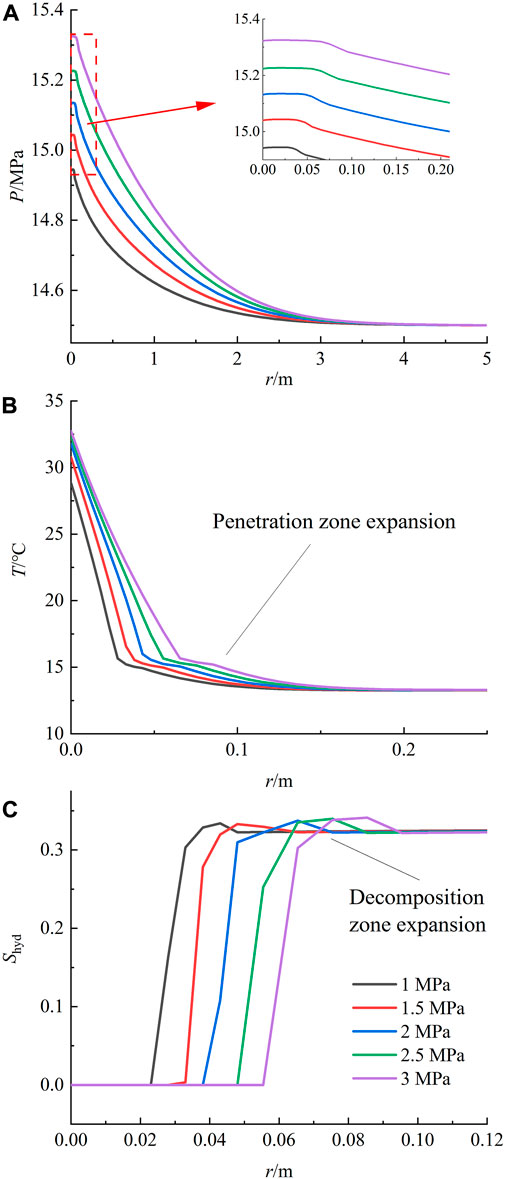
FIGURE 9. Changes in the main physical properties of the sediment around the wellbore at 25 min under varying cementing pressure differences. (A) Pressure. (B) Temperature. (C) Hydrate saturation.
Figure 9B shows the temperature distribution in the late sediment under different cementing pressure differences. The temperature increase near the wellbore wall is not obvious, but the range of the heat-up zone is significantly expanded. This is highly related to the depth of cement slurry penetration, which leads to the results in the figure due to the expansion of the cement slurry penetration and its exothermic influence. Based on the same principle, it can be seen from Figure 9C that the range of hydrate decomposition also expands significantly with increasing cementing pressure difference, and the decomposition zone increases from 2 to 6 cm in the studied range.
The effect of the cementing pressure difference on the sediment physical properties mainly presents in two aspects: 1) the sediment pressure increase and 2) the cement slurry penetration range expansion. Although the sediment pressure increase helps to stabilize the hydrate phase equilibrium, considering that GHBS are usually weakly cemented, excessive sediment pressure easily breaks the sediments. At the same time, the expansion of the cement slurry penetration zone is not conducive to the stability of GHBS, so the cementing pressure difference should not be too high in actual engineering.
4.1.3 Holding time of cementing pressure difference
The holding time of cementing pressure difference (HTPD) is the time when the cementing pressure difference exists and determines the duration of the cement slurry penetration process. Figure 10A shows the pressure distribution in the late sediment under different HTPDs. It can be seen that its effect on the sediment pressure is not significant, and the increase in the HTPD only slightly raises the sediment pressure. This is the result of two factors offsetting each other: 1) the longer HTPD causes more cement slurry to enter the sediment, which raises the sediment pressure and causes the thermal field to affect a larger zone; 2) it slows down the decomposition time of hydrate and delays the whole decomposition process of hydrate.
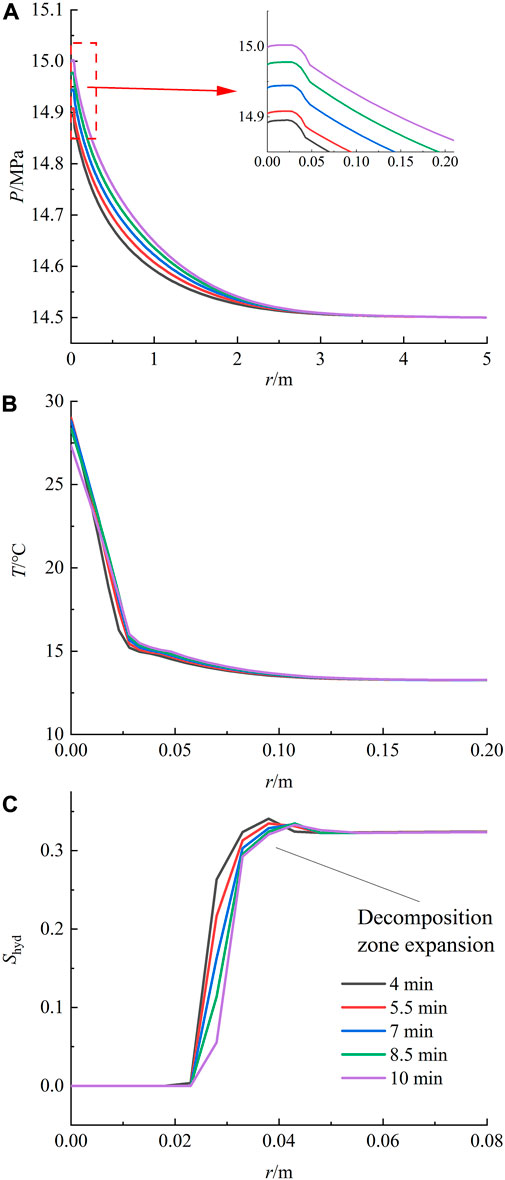
FIGURE 10. Changes in the main physical properties of the sediment around the wellbore at 25 min under different HTPDs. (A) Pressure. (B) Temperature. (C) Hydrate saturation.
Figures 10B, C show the temperature and hydrate saturation distributions in the late sediments under different HTPDs. As the HTPD increases, the range of the temperature field and hydrate saturation distribution in the sediment does not change significantly due to the hindering effect of the holding pressure process on hydrate decomposition.
The effect of HTPD on sediment physical properties is mainly due to its influence on the duration of the cement slurry penetration process, which causes two contradictory effects: 1) the amount and depth of cement slurry penetration increases with time, which promotes hydrate decomposition; 2) high pore pressure is maintained during holding pressure, which hinders hydrate decomposition and delays the start of hydrate decomposition. The effects of these are not significant in terms of the distribution of the physical properties of the sediment. However, in terms of cementing quality, it delays the decomposition of hydrate and increases time for cement hardening.
4.2 Influence of sediment physical properties on cement slurry penetration
4.2.1 Hydrate saturation
Hydrate saturation is one of the most important parameters of GHBS and directly determines the hydrate content in the pore space. Figure 11A shows the pressure distribution in the late sediment under different hydrate saturations. It can be seen that, on the one hand, with the increase in hydrate saturation, the pressure at the near wellbore wall increases subsequently, and on the other hand, the influence range of high pressure decreases. The former is because more hydrate can be decomposed in the range of cement slurry penetration, and more methane gas is produced by its complete decomposition, which increases the pressure at the near wellbore wall. The latter is due to the decrease in sediment permeability caused by the increase in hydrate saturation, which makes it difficult for the high-pressure fluid to dissipate to greater depth.
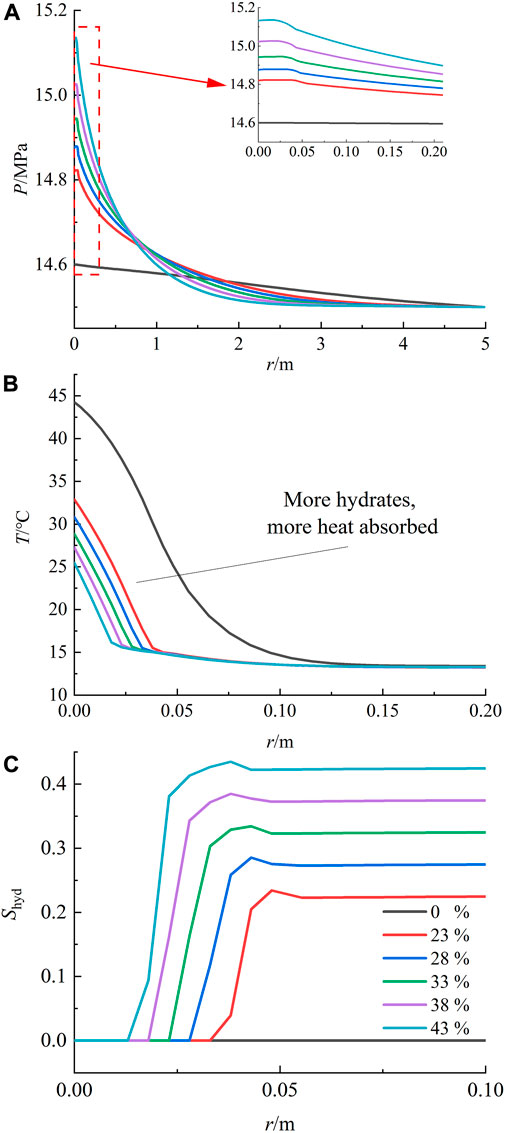
FIGURE 11. Changes in the main physical properties of the sediment around the wellbore at 25 min at different hydrate saturations. (A) Pressure. (B) Temperature. (C) Hydrate saturation.
Figure 11B illustrates the temperature distribution in the late sediments under different hydrate saturations. The image shows that the magnitude and extent of heat-up in the sediment decrease as the hydrate saturation increases. Both factors combine to cause this phenomenon due to the reduced extent of cement slurry penetration and more hydrate near the wellbore wall that can be used to mitigate the heat-up. Based on the same principle, it can be seen from Figure 11C that the extent of hydrate decomposition decreases as the initial hydrate saturation increases. Within the study area, the decomposition zone was reduced from 4 to 1 cm.
In summary, hydrate saturation affects GHBS mainly because 1) it determines the total amount of hydrate available for decomposition per unit volume of pore space, which in turn determines the degree of pressure increase due to methane gas production and the ability of the sediment to resist warming; 2) the hydrate occupies pore channels and reduces the permeability of pore spaces, which can impede fluid flow in them. Although the affected area in the sediment is smaller at higher hydrate saturation, the high pressure near the wellbore wall may be harmful to the quality of cementing, and the influence of this property should be taken into account in practical engineering.
4.2.2 Hydrate phase equilibrium temperature difference
The hydrate phase equilibrium temperature difference is the difference between the ambient temperature of the sediment and the hydrate phase equilibrium temperature at pore pressure, which indicates the degree of hydrate stability. Different hydrate phase equilibrium environments often imply differences in the initial pressure and temperature conditions of the sediment. For comparison purposes, the impact of sediment pressure increments and temperature increments on this parameter was used for evaluation. Figure 12A shows the distribution of pressure increments in the late sediments under varying hydrate phase equilibrium temperature differences. The picture shows that as the hydrate phase equilibrium temperature difference increases, the pressure increment in the whole sediment decreases. This is a direct effect due to the decrease in hydrate decomposition. The pressure increment at the wellbore wall was reduced from 0.5 to 0.2 MPa over the study area.
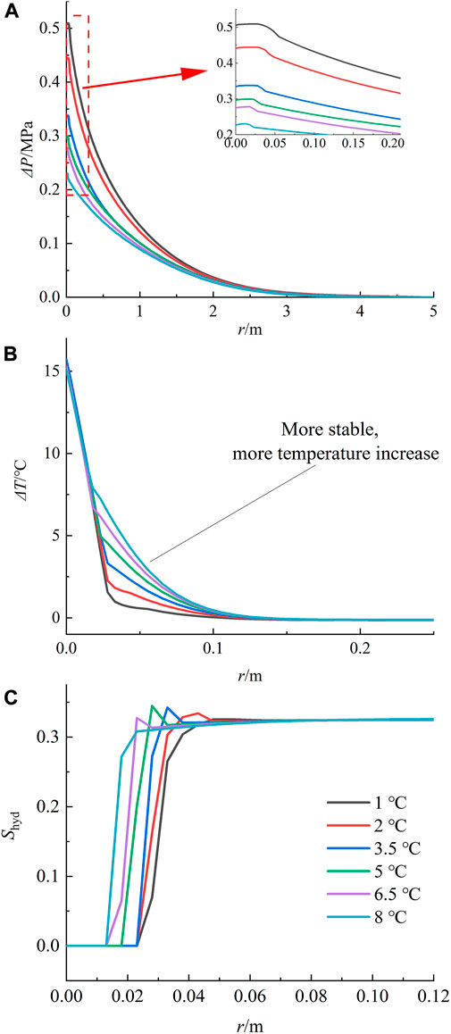
FIGURE 12. Changes in the main physical properties of the sediment around the wellbore at 25 min under different phase equilibrium temperature differences. (A) Pressure. (B) Temperature. (C) Hydrate saturation.
Figure 12B shows the distribution of temperature increments in the late sediment under different hydrate phase equilibrium temperature differences. The picture shows that with an increasing difference in hydrate phase equilibrium temperature, the temperature of the sediment near the wellbore wall does not change much, while the temperature slightly farther away increases significantly. This is because the hydrates near the wellbore wall are all completely decomposed, the heat absorbed is of the same value, and the heat up of the sediment at this location is consistent due to the constant total heat of cement decomposition. The hydrates slightly farther away are not completely decomposed. At this time, the total amount of hydrates decomposed in the sediments with high phase stability is less; thus, the heat absorbed by them is also less, which makes the temperature higher.
Figure 12C shows the distribution of hydrate saturation in the late sediment under different hydrate phase equilibrium temperature differences. With an increase in the difference, the decomposition range of the hydrate is obviously reduced.
The hydrate phase equilibrium temperature difference mainly affects the degree of hydrate decomposition; the more stable sediment decomposes less and produces less methane gas. Therefore, more attention should be given to sediments with poor phase stability in production.
4.2.3 Absolute permeability
Absolute permeability is an inherent property of porous media, and in conventional oil-gas sediment systems, it has a significant influence on the dynamic process of cement slurry penetration. In GHBS, this property depends mainly on the pore structure of the sediment, without considering the reservoir of hydrate it contains, and the absolute permeability of GHBS deposited in different environments varies greatly. Figure 13A shows the pressure distribution in the later sediments under different absolute permeabilities. The greater the permeability, the larger the influence range of the sediment pressure, while the pressure accumulated near the wellbore wall is smaller. This is because in the well permeable sediments, the high pressure near the wellbore wall dissipates rapidly to depth and cannot accumulate at the original location; thus, its pressure influence zone is wider, but the peak is lower.
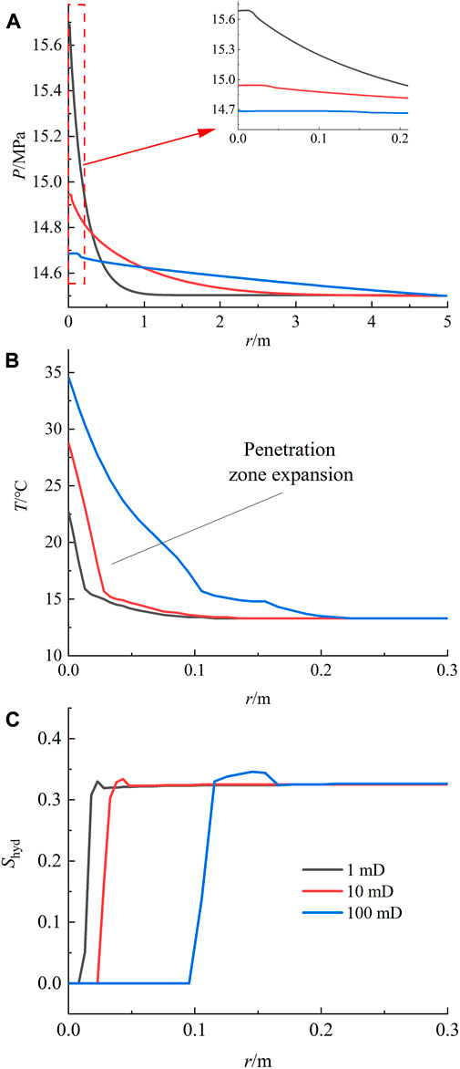
FIGURE 13. Changes in the main physical properties of the sediment around the wellbore at 25 min at different absolute permeabilities. (A) Pressure. (B) Temperature. (C) Hydrate saturation.
Figures 13B, C show the distributions of temperature and hydrate saturation in the late sediments under different absolute permeabilities. The heat-up and decomposition zones increase in the more permeable sediments, and the increase in permeability causes the decomposition zone to expand from 1 to 10 cm in the study. This is because better permeability facilitates the penetration behavior of cement slurry, leading to a wider area of cement slurry penetration, which in turn leads to a larger area of thermal radiation influence and a larger hydrate decomposition zone.
The absolute permeability mainly affects the efficiency of pore fluid flow, including the transport of cement slurry and decomposition products. The expansion of the cement slurry penetration zone causes the expansion of the heat-up and decomposition zones, which increases the amount of hydrate decomposition. However, it also effectively attenuates the pore pressure build-up and protects the sediments from fracturing.
4.2.4 Porosity
Porosity represents the effective porosity when hydrate saturation is zero. Porosity is a fundamental geophysical property of GHBS, and it also varies greatly in different depositional environments. Figure 14A illustrates the pressure distribution in late sediments under different porosities. The figure shows that the pore pressure hardly changes as the porosity increases. This is due to the pore environment being increased equiproportionally as the porosity increases while other parameters remain constant; that is, the volume of space in the environment, the hydrate content, the total amount of penetrating cement slurry, and the decomposed gases are all increased equiproportionally. These react to the surface to provide the results in the figure.
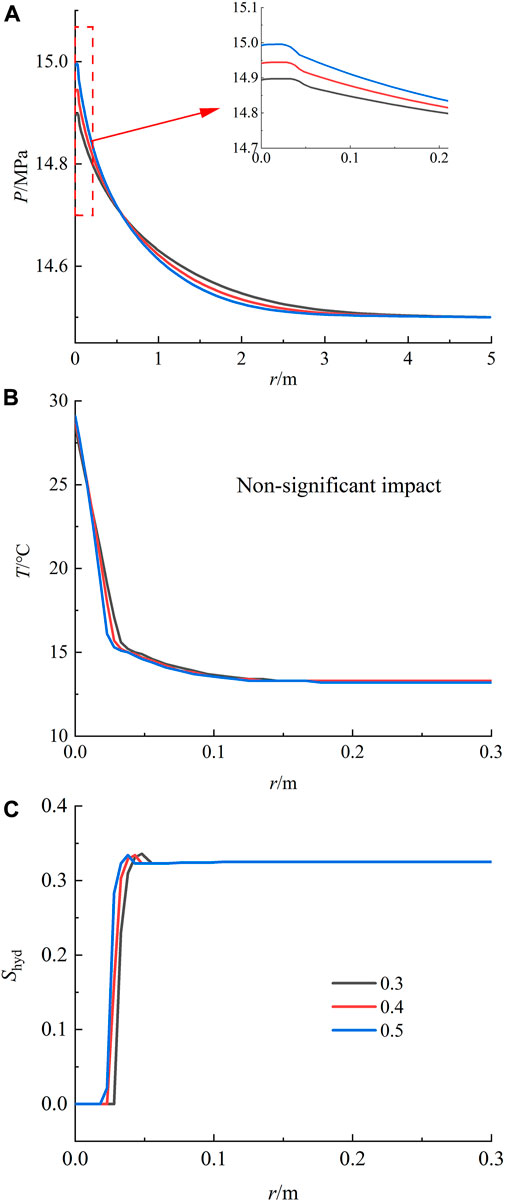
FIGURE 14. Changes in the main physical properties of the sediment around the wellbore at 25 min under different porosities. (A) Pressure. (B) Temperature. (C) Hydrate saturation.
Figures 14B, C show the distribution of temperature and hydrate saturation in the late sediment under different porosities. It can be seen that with the increase in porosity, the decomposition range of hydrate does not change much because the change in the penetration range of cement slurry is not very significant. Although the increase in the total amount of cement slurry penetration brings an increase in the exothermic heat, the increase in the total amount of hydrate hinders the increase in the temperature of the sediment, and the changes in the temperature field are not significant when the two factors cancel each other.
The increase in porosity facilitates the flow of pore fluid and increases the penetration of cement slurry. However, at the same time, the increase in its pore space indicates an equal increase in the material content in the pore space, and the volume of fluid that can be accommodated also increases, which is reflected as its effect on the physical properties of the sediment is less obvious. However, this is only for the sediment, and its increased fluid volume will certainly have a significant effect on the cement ring.
5 Conclusion
In this study, the GHBS explored at the SH2 station of GMGS-1, a gas hydrate drilling project in the Shenhu Area in the South China Sea, were the object of study. A numerical model of casing-annulus-sediment was constructed using TOUGH+HYDRATE, realistically reproducing the cement slurry exothermic and penetration processes by “continuous segmental simulation,” and the physical properties of GHBS around the wellbore during cementing were investigated. Then, single-factor controlled variable studies were conducted to investigate the changes in the physical properties of sediments under different cementing process parameters and sediment properties, which led to the following conclusions and insights.
(1) The main reasons for the increase in GHBS pressure during the cementing process include the reliance of the initial stage on the squeezing effect of cement slurry penetration on the sediment pores triggered by the cementing pressure difference, and the later stage generates high-pressure gas from hydrate decomposition to further increase the sediment pressure. In the early stage, the pressure distribution in the sediment is highest at the wellbore wall and gradually decreases deeper in the sediment. In the later stage, the high pressure brought by hydrate decomposition will make the pressure in the decomposition zone higher than the pressure near the wellbore wall. The main role of sediment heat-up comes from the hydration exotherm of the cement slurry, so the heat-up zone of the GHBS and the penetration zone of the cement slurry are highly coincident; thus, the decomposition of hydrate mainly occurs in the penetration zone of the cement slurry. In addition, because the decomposition of hydrate produces a large amount of methane gas and raises the pressure of the surrounding sediment, secondary hydrate will be formed in the annular space outside the decomposition zone. With the expansion of the decomposition zone, this hydrate high-saturation zone will also subsequently expand.
(2) Among the cementing process parameters, the hydration exothermic rate of the cement slurry determines the degree of sediment heating and has a drastic effect on the degree of hydrate decomposition in the penetration zone, which is completely decomposed when it is higher than 0.21 J·(g·s)−1 in the zone; therefore, low hydration heat cement slurry should be selected whenever possible in the actual project. The effects of increasing the cementing pressure difference on the physical properties of the sediment mainly include the increase in sediment pressure and the expansion of the cement slurry penetration zone. The former inhibits hydrate decomposition, while the latter increases the range of the heat-up zone and decomposition zone. The leading edge of decomposition in the study went from 2 to 6 cm in depth. Considering that GHBS are usually weakly cemented, the value of this parameter is not very large. The increase in HTPD increases the amount and depth of cement slurry penetration with time, so that the range of heat-up and decomposition zones increases. On the other hand, the extension of the HTPD delays the onset of hydrate decomposition. The combined effect on the physical properties of the sediment is not significant.
(3) Among the physical properties of the sediment, the effects of increased hydrate saturation mainly include increasing the total amount of hydrate per unit volume of pore space and decreasing the permeability of the pore space. It hinders the penetration of cement slurry, affects the diffusion of pore pressure, and reduces the influence of the heat-up and decomposition zones. Within the study area, the decomposition zone was reduced from 4 to 1 cm. At the same time, the pressure in the decomposition zone increases due to the increase in the total hydrate volume in this zone. The hydrate phase equilibrium temperature difference mainly affects the decomposition degree of hydrate in the heat-up zone, and the more stable sediment decomposes less and produces less methane gas. This results in a reduction of the pressure increment in the sediment, from 0.5 to 0.2 MPa at the wellbore wall over the study area. The absolute permeability mainly affects the pore fluid circulation efficiency, and a better permeability will increase the cement slurry penetration into the sediment, causing the expansion of the heat-up and decomposition zone, which changes from 1 to 10 cm in the study. However, it also effectively reduces the pore pressure accumulation and protects the sediment from fracturing. Porosity affects the pore volume of the sediment and the permeable volume of the cement slurry, and has a less pronounced effect on the physical properties of the sediment.
In summary, cement slurry penetration into hydrated sediments is a very complex process. Both the cementing process and the physical properties of the sediment significantly impact the process. At present, cementing GHBS in deep-water oil-gas drilling is still a difficult problem. The work in this paper lays the foundation for analyzing the effect of cement slurry penetration, which is important for the application of appropriate drilling techniques, accurate logging interpretation, wellbore stability evaluation and effective GHBS protection in engineering.
Data availability statement
The original contributions presented in the study are included in the article/supplementary material, further inquiries can be directed to the corresponding author.
Author contributions
XW: contributed to analysis, writing, experiment design, and data collection; MZ: contributed to conceptualization, methodology, analysis, writing, supervision, resources, and funding acquisition; KZ: contributed to experiment design, and data collection; QQ: contributed to investigation resources, and funding acquisition; ZW, SY, GZ, and TM: contributed to data collection, analysis, and writing. All authors have read and agreed to the published version of the manuscript.
Funding
This work was sponsored by the National Natural Science Foundation of China (No. 42272363), the National Natural Science Foundation of Sichuan Province (No. 23NSFSC1511).
Conflict of interest
The authors declare that the research was conducted in the absence of any commercial or financial relationships that could be construed as a potential conflict of interest.
Publisher’s note
All claims expressed in this article are solely those of the authors and do not necessarily represent those of their affiliated organizations, or those of the publisher, the editors and the reviewers. Any product that may be evaluated in this article, or claim that may be made by its manufacturer, is not guaranteed or endorsed by the publisher.
References
Chen, B. B., Sun, H. R., Zheng, J. J., and Yang, M. J. (2020). New insights on water-gas flow and hydrate decomposition behaviors in natural gas hydrates deposits with various saturations. Appl. Energy 259, 114185. doi:10.1016/j.apenergy.2019.114185
Li, Y., Cheng, Y. F., Yan, C. L., Wang, Z. Y., Zhang, Q. X., et al. (2022). Multi-physical field coupling model of hydrate formation and analysis of wellbore collapse law in Shenhu area of South China Sea. J. Central South Univ. Sci. Technol. 53 (3), 976–990.
Liu, T. L. (2018). Discussion on cementing technology scheme and problems of hydrate formation encountered in XX pre exploration well on northern slope of South China Sea. Wuhan): China University of Geosciences, 3–6.
Liu, T. L., Zheng, S. J., Wang, R., Sun, J. X., Jiang, G. S., Zhang, L., et al. (2018). Negative effect of cementing slurry invasion on gas hydrate stability around borehole wall. Acta Pet. Sin. 39 (8), 937–946.
Lu, F. (2013). Analysis of the impact of South China Sea energy on China's future energy security. Beijing: China Foreign Affairs University, 1–3.
Merey, Ş. (2019). Evaluation of drilling parameters in gas hydrate exploration wells. J. Petroleum Sci. Eng. 172, 855–877. doi:10.1016/j.petrol.2018.08.079
Moridis, G. J., Kowalsky, M. B., and Pruess, K. (2005). HydrateResSim users’ manual: A numerical simulator for modeling the behavior of hydrates in geologic media. Berkeley: Lawrence Berkeley National Laboratory.
Nakai, T., Tjok, K., and Humphrey, G. (2007). Deepwater gas hydrate investigation Shenhu survey area south South China Sea, offshore China. Guangzhou: Guangzhou Marine Geological Survey.
Ning, F. L., Wu, N. Y., Jiang, G. S., Zhang, L., Guan, J. A., Yu, Y. B., et al. (2010). A method to use solar energy for the production of gas from marine hydrate-bearing sediments: A case study on the Shenhu area. Energies 3, 1861–1879. doi:10.3390/en3121861
Ning, F. L., Zhang, K. N., Wu, N. Y., Zhang, L., Li, G., Jiang, G. S., et al. (2013). Invasion of drilling mud into gas-hydrate-bearing sediments. Part I: Effect of drilling mud properties. Geophys. J. Int. 193 (3), 1370–1384. doi:10.1093/gji/ggt015
Pang, L. Y. (2012). The characteristics and extension of depositional system and their relationship with hydrocarbon distribution in paleogene in north margin basins, south China sea. Beijing: China University of Geosciences.
Shen, Z. C., Wang, D., and Jia, Y. G. (2019). Analysis on gas hydrate exploitation response between the horizontal and vertical wells at SH 2 site in the Shenhu area of the South China Sea. Ocean Eng. 37 (4), 107–116.
Stone, H. (1970). Probability model for estimating three-phase relative permeability. J. Petroleum Technol. 22 (2), 214–218. doi:10.2118/2116-pa
Sun, H. R., Chen, B. B., Li, K. H., Song, Y. C., Yang, M. J., Jiang, L. L., et al. (2023). Methane hydrate re-formation and blockage mechanism in a pore-level water-gas flow process. Energy 263, 125851. doi:10.1016/j.energy.2022.125851
Sun, J. X. (2018). Characteristics of reservoir response to drilling and production in gas hydrate-bearing sediments in the South China Sea. Wuhan. Wuhan): China University of Geosciences, 48–52.
Sun, Z., Zhang, C. M., Wang, X., Li, P. C., Sun, L. T., Zhang, Y. F., et al. (2011). China's offshore oil and gas industry. Guangzhou: Guangdong Economic Publisher, 14–16.
Tinku, S., and Vikas, M. (2018). Experimental investigations and optimizations of rheological behavior of drilling fluids using RSM and CCD for gas hydrate-bearing formation. Arabian J. Sci. Eng. 43, 6541–6554. doi:10.1007/s13369-018-3292-1
Tu, Y. Z., Ning, F. L., Jiang, G. S., Wu, N. Y., and Zhang, L. (2010). Mechanism and characteristics of invasion of drilling fluid in gas hydrates-bearing formation. Geol. Sci. Technol. Inf. 29 (3), 110–113.
Van, G. M. T. (1980). A closed-form equation for predicting the hydraulic conductivity of unsaturated soils. Soil Sci. Soc. Am. J. 44 (5), 892–898. doi:10.2136/sssaj1980.03615995004400050002x
Wang, D. D. (2021). Geological characteristics and physical properties of low permeability and weakly consolidated hydrate reservoirs in the South China Sea. Wuhan: China University of Geosciences.
Wang, J. Q. (2021). The way to explore marine oil and gas resources. Nat. Resour. Sci. Cult. (4), 20–23.
Wang, X. J., Hutchinson, D. R., Wu, S. G., Yang, S. X., and Guo, Y. Q. (2011a). Elevated gas hydrate saturation within silt and silty clay sediments in the Shenhu area, South China Sea. J. Geophys. Res. Solid Earth 116 (5), B05102. doi:10.1029/2010JB007944
Wang, X. J., Wu, S. G., Lee, M., Guo, Y. Q., Yang, S. X., and Liang, J. Q. (2011b). Gas hydrate saturation from acoustic impedance and resistivity logs in the Shenhu area, South China Sea. Mar. Petroleum Geol. 28 (9), 1625–1633. doi:10.1016/j.marpetgeo.2011.07.002
Weng, T. W., Lo, S. C., Huang, J. H., and Li, C. F. (2013). The general situation of the distribution and potential volume of gas hydrate in the south China sea. Min. Metallurgy (222), 56–70.
Wu, N. Y., Zhang, H. Q., Su, X., Yang, S. X., Zhang, G. X., Liang, J. Q., et al. (2007a). High concentrations of hydrate in disseminated forms found in very fine-grained sediments of Shenhu area, South China Sea. Terra Nostra 1 (2), 236–237.
Wu, N. Y., Zhang, H. Q., Yang, S. X., Liang, J. Q., and Wang, H. B. (2007b). Preliminary discussion on natural gas hydrate (NGH) reservoir system of Shenhu area, north slope of South ChinabSea. Nat. Gas. Ind. 27 (9), 1–6.
Xi, F. Z., Sun, F. Q., Yang, K. P., Liu, A. P., Wang, Y. H., Song, B. L., et al. (2020). Cement slurry for hydrate well cementation and preparation method thereof. China, CN111056784A.
Xu, M. B., Wang, X. L., Zhou, J. L., Jiang, S. Q., Wang, Y. Q., Zhu, R. D., et al. (2014). The research of low-heat slurry for cementing in the natural gas hydrate formation. J. Oil Gas Technol. 36 (11), 134–137.
Yang, G. K., Jiang, G. S., Liu, T. L., Qin, X., and Yu, Y. F. (2021a). Analysis on preparation of temperature controlled self-repairing microcapsules and its application in cement slurry for hydrate formation. Mater. Rep. 35 (2), 2032–2038.
Yang, G. K., Liu, T. L., Zhu, H., Zhang, Z. H., Feng, Y. T., Leusheva, E., et al. (2022). Heat control effect of phase change microcapsules upon cement slurry applied to hydrate-bearing sediment. Energies 15 (12), 4197. doi:10.3390/en15124197
Yang, G. K., Wang, A. M., Yin, S. T., Dai, T., Liu, T. L., and Jiang, G. S. (2021b). Preparation and application of phase change microcapsules for low heat cement slurry for well cementing in hydrate formation. Drill. Eng. 48 (3), 118–124.
Yang, L., Guan, D. W., Qu, A. X., Li, Q. P., Ge, Y., Liang, H. Y., et al. (2023). Thermotactic habit of gas hydrate growth enables a fast transformation of melting ice. Appl. Energy 331, 120372. doi:10.1016/j.apenergy.2022.120372
Yang, S. X., Liang, J. Q., Lu, J. A., Qu, C. W., and Liu, B. (2017). New understandings on the characteristics and controlling factors of gas hydrate reservoirs in the Shenhu area on the northern slope of the South China Sea. Earth Sci. Front. 24 (4), 1–14.
Zhang, H. Q., Yang, S. X., Wu, N. Y., Su, X., and Holland, M. (2007). Successful and surprising results for China's first gas hydrate drilling expedition. Fire Ice Newsl. 9.
Zhang, H. W., Cheng, Y. F., Li, L. D., Shi, J. H., Jiang, L., and Han, X. T. (2018). Perturbation simulation of invasion of drilling fluid containing thermodynamic hydrate inhibitors into natural gas hydrate formation. Sci. Technol. Eng. 18 (6), 93–98.
Zhang, J. B., Li, B., Jin, H., Chen, Y., Lu, Y. W., and Wang, L. (2020). Study and application of a low hydration heat cement slurry system for the cementing of deepwater hydrate layer. China Offshore Oil Gas 32 (1), 119–124.
Zhang, J. H., Wei, W., and Wang, H. Y. (2009). Research on gas hydrate and its development techniques. Nat. Gas. Technol. 3 (2), 67–69+80.
Zheng, M. M., Jiang, G. S., Liu, T. L., Peng, L., Ning, F. L., Liu, L., et al. (2017). Physical properties response of hydrate bearing sediments near wellbore during drilling fluid invasion. Earth Sci. 42 (3), 453–461.
Zheng, M. M., Liu, T. L., Jiang, G. S., Wei, M., Huo, Y. X., and Liu, L. (2020). Large-scale and high-similarity experimental study of the effect of drilling fluid penetration on physical properties of gas hydrate-bearing sediments in the Gulf of Mexico. J. Petroleum Sci. Eng. 187, 106832. doi:10.1016/j.petrol.2019.106832
Zheng, M. M., Wang, X. Y., Zhou, K. R., Wang, K., Wu, Z. R., Jiang, G. S., et al. (2022). Critical conditions identification of generated high-pressure gas and water reverse penetration during cementing in hydrate reservoirs in the South China Sea. J. Central South Univ. Sci. Technol. 53 (3), 963–975.
Zheng, M. M., Wang, X. Y., Zhou, K. R., Wang, K., Wang, Z. L., Dong, G., et al. (2021). Hydrate reservoir physical properties response and high-pressure gas-water reverse penetration during deepwater oil and gas cementing. Coal Geol. Explor. 49 (3), 118–127.
Keywords: natural gas hydrate, deep-water oil-gas cementing, physical properties response, dynamic exothermic source, continuous segmental simulation, cementing process and geological conditions
Citation: Wang X, Zheng M, Zhou K, Qi Q, Wu Z, Yan S, Zeng G and Ma T (2023) Physical property response of peri-well sediments during cementing of gas hydrate-bearing sediments in conventional oil-gas wells in the South China Sea. Front. Earth Sci. 11:1131298. doi: 10.3389/feart.2023.1131298
Received: 24 December 2022; Accepted: 09 March 2023;
Published: 17 March 2023.
Edited by:
Giovanni Martinelli, National Institute of Geophysics and Volcanology, ItalyReviewed by:
Jiafei Zhao, Dalian University of Technology, ChinaYang Mingjun, Dalian University of Technology, China
Copyright © 2023 Wang, Zheng, Zhou, Qi, Wu, Yan, Zeng and Ma. This is an open-access article distributed under the terms of the Creative Commons Attribution License (CC BY). The use, distribution or reproduction in other forums is permitted, provided the original author(s) and the copyright owner(s) are credited and that the original publication in this journal is cited, in accordance with accepted academic practice. No use, distribution or reproduction is permitted which does not comply with these terms.
*Correspondence: Mingming Zheng, bWluZ21pbmcuemhlbmdAaG90bWFpbC5jb20=