 Yang Tao*
 Liu Shuailei
- School of Urban Planning and Municipal Engineering, Xi’an Polytechnic University, Xi’an, Shaanxi Province, China
The impact of shield construction on the close lateral passing of high-speed railways can threaten the safety of operating high-speed railways. To study the deformation characteristics of the shield structure after the application of isolation piles from the ground surface and the deformation characteristics of the bridge piers of an overpassing high-speed railway, we analyze the mechanism of isolation pile restraint control and establish a three-dimensional numerical model of a shield structure to study the situation of a high-speed railway with a metro interval under passing a high-speed railway passenger line project. Combined with the measured data and numerical simulation data of the same construction stage, we study the impact of shield structure lateral passing on high-speed railway piers and surrounding ground surface in terms of the disturbance changes and the effect of isolation, as well as the effect of the lateral passing of the shield tunnel on the surface of the bridge piers and the surrounding area and the control effect of the isolation piles on the deformation. The results show that the isolation pile can block the development of the soil layer rupture surface and the stress path. The isolation pile has a good control effect on the vertical displacement of the bridge pier. The vertical displacement of the bridge pier decreases from 0.6 mm to 1.1 mm after the single- and double-track tunneling, and the displacement changes along the depth direction from non-uniform to relatively uniform. The vertical displacement of the ground surface includes both uplift and settlement, which occur at the same time. When the shield tunneling advances, the form of the ground settlement trough is changed from a “V” shape formed by the right single-track tunneling to a “W” shape after the double-track tunneling. The isolation pile can effectively control the influence range of tunnel excavation; its lateral displacement form changes regularly, and the lateral uplift is always in a “double-C outward expansion” shape. The initial excavation greatly disturbs the initial stress field, so it is necessary to pay attention to the control and management of measures to destroy the initial stress field.
1 Introduction
The 14th Five Year Plan and the Outline of Vision Goals for 2035 propose that in the next 5 years, China’s urban rail transit network will be increased by another 3,000 km. The scale of the high-speed railway network will continue to expand, which will inevitably lead to tunnel crossing and passing. However, the construction of a shield tunnel laterally passing a high-speed railway with a pier pile foundation will disturb the stress state of the surrounding strata and soil and thus cause stress changes and deformation of the surrounding and upper soil layers, threatening the operational safety and driving comfort of existing high-speed railways (Yao et al., 2012; Liao and Sangrey, 2016; Yao et al., 2019; Jia et al., 2022). The lateral passing of shield structures past existing high-speed railway lines in a water-rich sand layer is characterized by a wide range of stratigraphic disturbances, high line deformation requirements, and difficult construction control. It is important to study the deformation characteristics of the shield structure after the application of isolation piles from the ground surface and the deformation characteristics of the piers of the high-speed railway to ensure the smooth operation of the existing high-speed railways and the safety of the construction of the new laterally passing metro shield tunnel (Ma et al., 2015; Chen et al., 2016; Huang et al., 2021).
Comprehensive research in recent years has found that scholars have mainly used numerical simulation and field monitoring methods to explore more about the working mechanism of shield tunnels under passing buildings and passing an adjacent tunnel of a certain project, but there has been a relative lack of focus on analyzing the influence of containment control and the barrier effect of isolation piles. Some scholars (Beyabanaki and Gall, 2017; Shan et al., 2021; Zhang et al., 2021; Wei et al., 2022) have conducted a deformation simulation of a shield interval under a high-speed rail-way bridge pile foundation to evaluate the control effect of isolation piles from multiple angles and concluded that isolation piles can significantly reduce the impact of the superposition effect on bridge piles caused by two-lane tunnel excavation. According to the influence mechanism of shield structure transverse channel disturbance on tunnel deformation under special circumstances such as deep coal mine and the analysis of the model of shield tunnel ultra-close crossing pile group, some scholars (Wu et al., 2021; Yu et al., 2021; Huang et al., 2022; Pan et al., 2022; Ren et al., 2022; Yuan et al., 2022) have obtained the deformation and failure mechanism of shield tunnel under special conditions. Other researchers (Dezi et al., 2012; Liu et al., 2022; Zhou et al., 2022) have established an analytical model of pile-soil interaction, introduced the deformation coordination relationship, and verified it by comparing the analytical solution with measured data to reveal the mechanical mechanism of the effect of isolation piles on the vertical dis-placement of the ground.
In this paper, we use numerical simulation and measurement analysis of a project with a crossing high-speed railway and urban subway to study the deformation characteristics of the abutment and the shield structure of the high-speed railway after the application of an isolation pile from the ground surface, we analyze the influence of the shield structure laterally passing the abutment of the high-speed railway, the surrounding ground surface disturbance changes and the effect of the isolation pile restraint control, ensuring the operational safety of the existing high-speed railway, and we provide a reference for similar projects in the future.
2 Analysis of the mechanism of isolation pile drift control
2.1 The impact of tunnel boring on the surrounding environment
The trend of upper strata displacement after tunnel excavation and unloading is shown in Figure 1 below. When the initial stress field and displacement field change during soil excavation, the soil is removed, resulting in surface settlement. According to Peck’s empirical equation (Eq. 1) (Fattah et al., 2013; Zhang et al., 2020), the horizontal surface deformation during tunnel excavation is considered to approximately follow a Gaussian distribution, where W is half of the total width of the surface settlement trough; Smax is the maximum settlement; α is the angle of the influence range and is related to the ground conditions; R is the tunnel radius; and h is the total depth from the surface to the tunnel center.
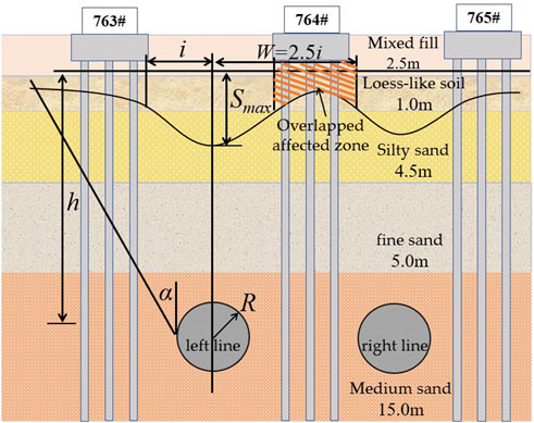
FIGURE 1. Schematic representation of the ground deformation mechanism of tunnel excavation.
Eq. 1: x is the horizontal distance of the surface settlement from the tunnel axis; S(x) function of x across the surface; A is the tunnel excavation cross-sectional area; and V1 is the tunnel volume loss rate, for which the small- and medium-diameter tunnel volume loss rates are generally between 0% and 2.0%.
2.2 Mechanism of isolation pile action
At present, the design of isolation piles is based on experience and lacks systematic and reliable guidance. In this paper, the typical geological conditions of a water-rich sand layer are used as the basis for qualitative analysis based on numerical calculation. When the displacement field changes after tunnel excavation and unloading, isolation piles are applied between the high-speed railway piers and the excavated tunnel, and the depth of the embedded isolation piles reaches approximately 3 m below the bottom of the tunnel. In Figure 2A is the effect of soil stress disturbance directly caused by excavation; B is the stress that has been transferred to the railway bridge pile; C is the lateral frictional resistance of the isolation pile caused by surface settlement; and D is the effect of the isolation pile on the lateral earth pressure.
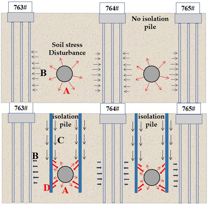
FIGURE 2. Mechanism of isolation pile action.
When the soil is deformed due to excavation, the deformation is transferred to the pile location and will cause the pile to move and deform, but the displacement and stress of the isolation pile will also develop synchronously, and resist the influence at the same time (Zhang et al., 2022; Weng et al., 2023, Qiu et al., 2022). Although the soil stress disturbance caused by excavation is continuously transmitted the lateral earth pressure is constrained by the isolation pile, and the two effects cancel each other out, so the stress that is transmitted to the railway bridge pile is greatly reduced.
Isolation piles mainly bear the lateral earth pressure caused by excavation and the frictional resistance generated by surface settlement. Isolation piles provide lateral resistance to limit the development of soil deformation behind the pile and constrain the surface settlement, changing the shape of the surface settlement trough and effectively reducing the maximum settlement of the surface; the constraining effect is most obvious at the location of isolation piles, and the constraining effect decays away from the isolation piles; on the other hand, isolation piles can reduce the earth pressure acting on the high-speed railway bridge piles to a certain extent (Bilotta and Russo, 2011; Zhang et al., 2022).
3 Engineering reinforcement and monitoring program
3.1 Project background
The geomorphological unit of the shield passing interval belongs to the Weihe River first-order terrace and Weihe River diffuse beach area, with flat terrain and ground elevation generally ranging from 370.62 to 373.85 m. The groundwater of the site belongs to the Fourth Series, and its aquifer is mainly a strongly permeable sand layer, which belongs to the Fourth Series Holocene and Upper Pleistocene strata; the soil information is shown in Figure 1; Table 1 below.

TABLE 1. Site soil layer information.
The minimum horizontal distance between the outer edge of the tunnel and the bridge piles of the Ba River Special Bridge of the Zhengxi and Daxi Passenger Special Lines is approximately 8.95 m and 8.5 m, respectively, which is greater than one times the diameter of the tunnel. The concrete continuous girder bridge structure has a pile foundation of bridge piers; the bearing platform includes nine piles and one bearing platform, the height of the bearing platform is 3 m, and the diameter of the pile foundation under the bearing platform is 1.5 m.
3.2 Shield parameters control
(1) To properly maintain the soil pressure equilibrium and reduce the pressure fluctuation, considering the geological conditions of the shield and soil and the parameters of the 200 m shield test section, the soil bin equilibrium pressure is increased by 0.1–0.2 bar, set at 1.0–1.2 bar. The shield advance speed is mainly related to the frontal soil bin pressure, jack thrust, soil layer nature, and other factors. When crossing, we should consider the synergistic influence of multiple factors, adjust the advance speed appropriately and stabilize the total thrust of the shield machine to reduce the stratum disturbance. The tunnel passes through the medium sand layer, the engineering experience in such stratum results in a shield advance speed of 35–55 mm/min, the average daily feed is 14–18 m, and the actual speed during the passing is controlled at 35–40 mm/min.
(2) For grouting during the shield structure construction of the underpass high-speed railway, double-index control (grouting volume and grouting pressure) is adopted, and the grouting volume per ring should reach 6.2 m3 when tunneling through the sand layer in the full section to maintain grouting volume control. When crossing the high-speed railway section, the grouting amount should be 0.3–0.4 times higher than that of the ordinary section, that is, 7.8–8.5 m³. To ensure the control of settlement after shield construction, it is necessary to perform a second grouting of the ring hoop in the hole during shield construction (Xiang et al., 2008).
3.3 Reinforcement scheme
With the relevant engineering experience and the specific situation of underpass construction, to avoid the impact on the bridge pile foundation as much as possible, the construction of grouting piles first occurs on both sides of the proposed tunnel, which is then excavated through, using the reinforcement program of bored isolation piles and synchronous grouting.
(1) Φ800 mm bored isolation piles, PVC pipe with a 48 mm diameter, and water stop-grouting are adopted, and the pile spacing is 1,100 mm. Near the bridge pier, along both sides of the shield tunnel, the horizontal layout range is at least 9.5 m on both sides of the elevated railway bearing platform, the center distance between an isolation pile and a bridge pile is at least 6.5 m, and the net distance between an isolation pile and the interval tunnel is 2 m, as shown in Figure 3 below.
(2) For the shield excavation sequence, single-line construction is adopted, with the right-line shield tunnel construction first, and then the left-line tunnel is constructed after the effect of the settlement on the soil layer is eliminated and the ground stress is stabilized to avoid the superposition of settlement effects and excessive ground stress and deformation caused by the simultaneous construction of two tunnels.
(3) For the shield excavation work, additional grouting holes are set up in the pipe section within 30 m on both sides of the railway bridge pile, two grouting holes are added in the adjacent block and the standard block, and the number of grouting holes in each ring section of the original common section is increased from 10 to 16; after the shield crossing, the grouting reinforces the stratum behind the pipe to reduce the ground settlement; the grouting slurry used after the pipe is installed adopts a liquid 1:1 cement: water glass double-liquid slurry and the grouting range is 3 m outside the tunnel profile.
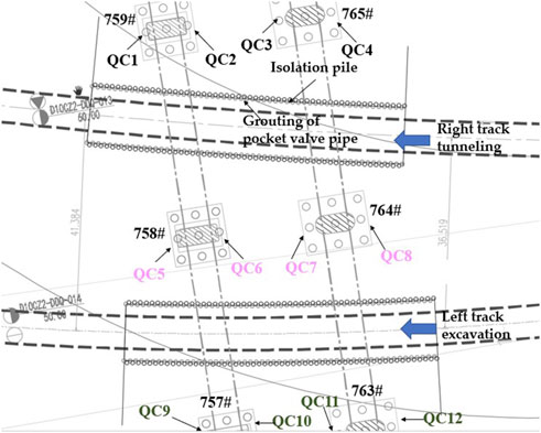
FIGURE 3. Layout plan of isolation piles in the under-crossing section.
3.4 Monitoring frequency and scope
According to the environmental conditions of the site and the direction of the line, the monitoring frequency is adjusted in real time according to the changes in the construction stage. The range of longitudinal measurement is from 35 m after the shield tail to 25 m before the cutter plate, and the monitoring range of surface disturbance and subsidence changes simultaneously as the shield continues to advance. (Cheng et al., 2018; Huang et al., 2021). The monitoring items mainly include surface subsidence, settlement changes in the high-speed railway piers, and cumulative settlement difference of adjacent high-speed railway piers. The monitoring frequency is the critical period of construction, 1 time/hour or 1 time/2 h in general and 1 time/2 days afterward, after which appropriate adjustments are made according to the deformation stability.
For each high-speed railway, the bridge pier should have no less than 4 monitoring points, the upper 2 monitoring points should be arranged at the top of the pier, and the lower 2 monitoring points should be arranged at the bottom of the pier to meet the appropriate location of the visibility conditions. The monitoring point layout is fixed with an L prism (epoxy adhesive) in the area of tunneling affected by the scope of the pier, pier support burial, and tunnel construction. Bridge pier measurement points are arranged in Figure 4 below.
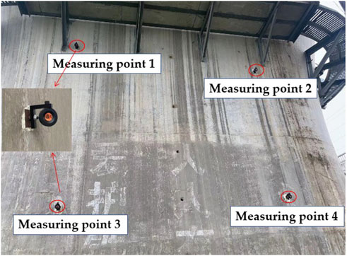
FIGURE 4. Layout of the pier measuring points.
4 Numerical simulation calculations
4.1 Calculation assumptions and parameters
To effectively simulate the construction process of the lateral passing of a shield machine during—high-speed railway construction, reasonable calculation assumptions are adopted (Ma et al., 2021): 1) the soil layers are assumed to be uniform and horizontally layered, and the soil is an isotropic elastic-plastic body; 2) the influence of groundwater changes is not considered; 3) the equivalent load substitution method is used to calculate the load of both the superstructure and the original high-speed railway; 4) the model parameters such as stratigraphic parameters are assigned according to the range of values in the geological survey report (see Table 1 above). According to the previous simulation experience in this area, the elastic modulus of elasticity of the simulated soil is 4.5 times its compressive modulus.
According to the location of the shield underpass interval and the high-speed railway of the Daxi and Zhengxi Passenger Line, the finite element program MIDAS GTS 3D was used for finite element simulation and numerical calculation. The model takes into account factors such as soil layering, soil non-linearity, the top thrust of the shield, pipe sheet, and simultaneous grouting behind the shield wall during construction; The simulated boundary conditions are free constraint, lateral constraint horizontal displacement, bottom constraint horizontal displacement and vertical displacement; The elastic constitutive model is selected for the structural part such as the tunnel tube sheet, and the Modified Mohr-Coulomb constitutive model is selected for the numerical simulation of the calculated soil layer (Lv et al., 2020). Taking into account the calculation accuracy and the boundary effect of excavation, the model dimensions are 180 m × 150 m × 70 m, which meets the requirements of the tunnel diameter. The model is shown in Figure 5 below.
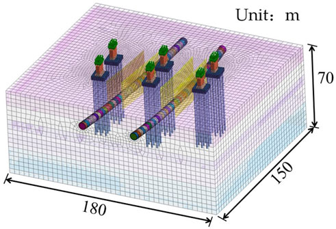
FIGURE 5. Overall model.
4.2 Calculated working conditions
Simulation of the lateral passing shield excavation process is achieved by using functions such as passivation and activation of units in the MIDAS GTS construction simulation step. After balancing the initial stress field, the current excavated soil unit is passivated to activate the corresponding shield shell unit and support pressure, and the previous shield shell unit, support pressure, and grouting pressure are passivated to activate the corresponding grouting layer unit, pipe sheet unit and circumferential grouting and boring pressure, as shown in Figure 6 below. Subsequent excavations repeat the above steps with the excavation process to gradually activate the structure and blunt the corresponding forces until the left and right lines are fully excavated.
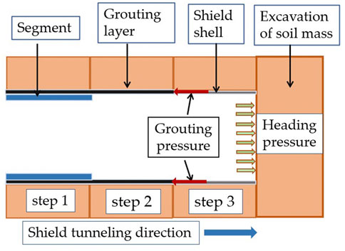
FIGURE 6. Schematic diagram of excavation.
5 Analysis of calculation and monitoring results
5.1 Analysis of bridge pier calculation results
To study the deformation effect of the applied isolation pile when the left and right lines of the shield interval are close to the lateral passing, with or without the applied isolation pile as the variable, the simulation calculation results of the left and right lines when the laterally passing is completed are selected for comparison and analysis, and the same points as the field monitoring are selected. Figures 7, 8 below show the settlement contour maps of the railway piers.
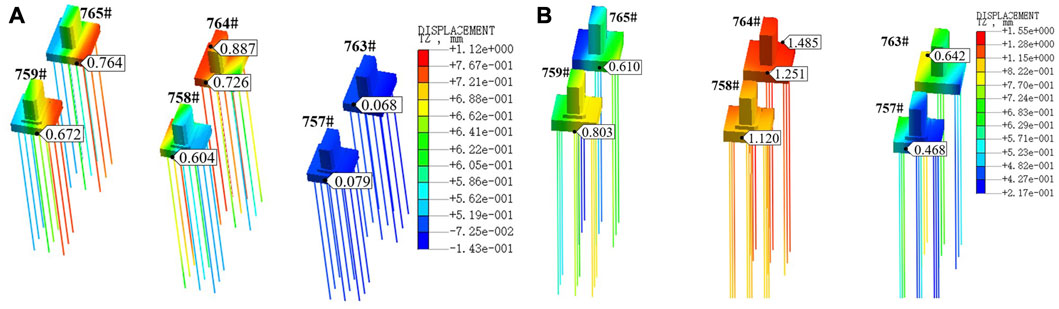
FIGURE 7. Vertical displacement of the piers (without isolation piles): (A) right line through and (B) left line through.
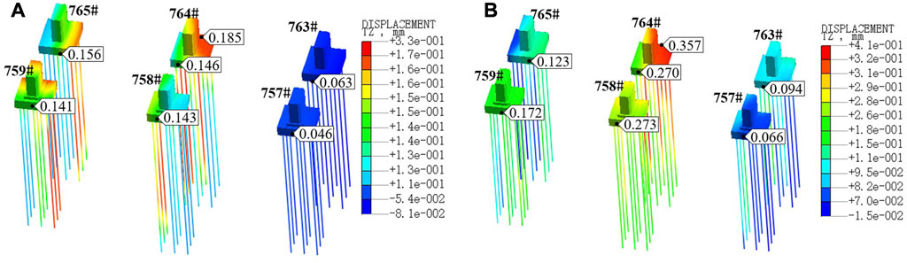
FIGURE 8. Vertical displacement of the piers (with isolation piles) (A) right line through, (B) left line through.
The results of the vertical displacement changes of the bridge piers under the shield structure passing through the Zhengxi and Daxi Passenger Line projects are compared and analyzed in Figures 7, 8. When the isolation piles were not applied, with continuous tunneling, the shield construction had an increasing influence on the bridge piers. After the shield tunneling of the left and right lines passed, the displacement of the bridge pier bearing platform ranged from 0.2 mm to 1.55 mm; the bridge piers on both sides outside the shield tunnel bulged at approximately 0.6 mm, while central piers No. 764 and No. 758 were in the overlapping influence area affected by the excavation of the two lines and were most affected by the excavation. The change in pier uplift nearly doubled to 1.5 mm. When the isolation piles and reinforcement measures were applied, the displacement of the bridge pier bearing platform was approximately 0.15 mm, and the vertical displacement reduction was 0.6 mm when the right line shield tunneling passed; when both the left and right line shield tunneling passed, the maximum elevation of the bridge pier was still observed at pier No. 764 in the overlapping influence area, and its elevation was 0.410 mm, but the reduction in the vertical displacement of the bridge pier reached 1.1 mm, and the left side of the No. 763 and 757 piers on the left side was in a stable state because the left line was in a stable state due to the isolation pile protection and reasonable construction process.
From the data comparison in Figure 9 above, it can be seen that the blocking effect on vertical displacement is particularly obvious after the application of isolation pile-reinforced soil. As shown by the displacement change of the isolation pile, the isolation pile bears most of the soil disturbance from the shield excavation, thus greatly weakening the impact of shield excavation on the deformation of the high-speed rail-way pier; at the same time, the isolation pile reduces the change in vertical displacement by blocking the development of the soil rupture surface and the stress change path, indicating that the isolation pile has a better control effect on the vertical displacement of the bridge pier.
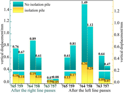
FIGURE 9. Working condition comparison displacement change.
5.2 Surface deformation analysis
The ground surface between Daxi and Zhengxi Passenger Line tunnels was selected as the object of study. Figure 10 shows the settlement changes of the left and right lines passing without the application of isolation piles, the single line passing of the right line after the application of isolation piles, and the left and right lines passing after the application of isolation piles. The analysis of the results in the figure shows that the overall settlement trend is in accordance with the maximum ground settlement trend. When the shield tunnel passes through, the extrusion deformation of the tunnel vault caused by soil unloading forms a ground settlement trough centered on the vault with a width of approximately 35 m; the settlement trough shape changes from a “V” shape formed by the single line boring in the right line to a “W” shape after the left and right lines pass. In either case, the deepest part of the settlement trough is located directly above the tunnel (Song, 2021); the settlement values after the single-line and double-line boring were not considerably different when the isolation pile was applied, and the maximum settlement value was approximately 1.2 mm, while the maximum settlement value after the left and right lines passed without the isolation pile was 1.41 mm.
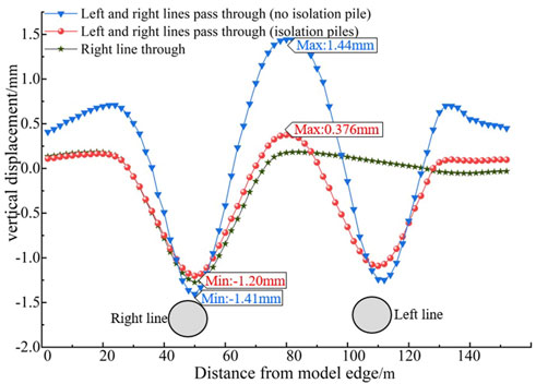
FIGURE 10. Vertical displacement of the ground surface.
However, the analysis in Figure 11 shows that the isolation piles significantly reduce the influence of the tunnel excavation on the surrounding soil: without the isolation piles, the influence of the tunnel excavation can be extended to the abutment of the high-speed railway; after the isolation piles are applied, the influence is obviously limited to the area between the two rows of isolation piles. The influence area of the left and right lines is reduced from the surrounding soil to the surface to the middle of the isolation pile and below the surface, while the soil displacement under the tunnel changes little. As shown in the cross-section in Figure 11 below, without the application of isolation piles, the main impact width of surface settlement is 23.9 m in the right line and 14.3 m in the left line; after the application of isolation piles, the impact width of the right line is reduced to 12.3 m, a reduction of 48.5%, and the impact width of the left line is reduced to 8.2 m, a reduction of 42.7%, indicating that the application of isolation piles can effectively control the impact of tunnel excavation. This shows that the application of isolation piles can effectively control the impact of tunnel excavation, greatly reduce its impact width, and play an effective role in isolation protection.
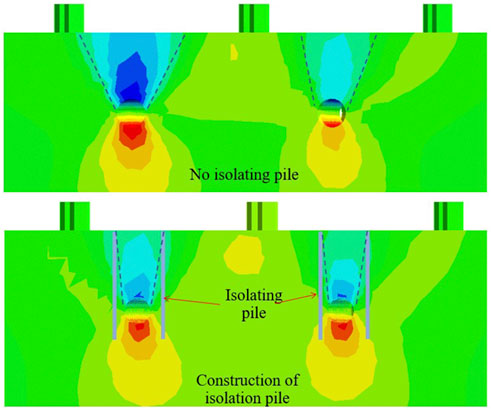
FIGURE 11. Comparison contour maps of the total displacement impact widths.
The resulting surface vertical deformation is in the form of uplift and settlement occurring at the same time. The surface uplift deformation is mainly in the overlap-ping influence area of the two-lane tunnel. The shield tunneling disturbs the ground, and the magnitude of surface uplift increases continuously as the left line proceeds. When the isolation pile is not applied, the surface uplift reaches 1.44 mm, but when the isolation pile is applied, the maximum uplift is only 0.376 mm, and the reduction rate reaches 74%, which again shows that the isolation piles can effectively isolate the development of the soil rupture surface and ground disturbance and thus reduce the increase in vertical displacement.
5.3 Deformation analysis of isolation piles
As the main reinforcement structure, the isolation pile works together with grouting to provide stable protection for the bridge pier and maintain the deformation of the surrounding soil layer. Figure 12 shows the horizontal and vertical deformation contour maps of the isolation pile after the completion of the lateral passing of the shield’s right line.
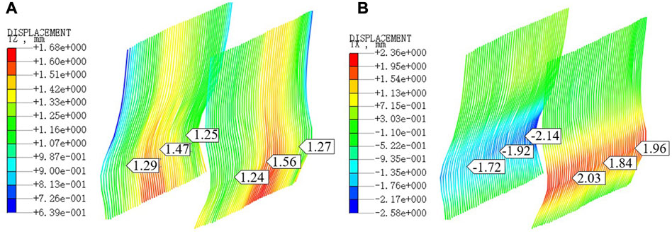
FIGURE 12. Contour diagram of change in the displacement of the isolation pile: (A) vertical displacement of isolation pile, (B) horizontal displacement of isolation pile.
As shown in Figure 12, with the continuous excavation of soil, the joint action of excavation and grouting pressure forms a circular outward thrust, and the horizontal displacement of the isolation pile gradually increases, making the displacement de-formation range stable at 1.7–2.1 mm. Due to the gradual and stable excavation process, the lateral displacement pattern of the isolation pile changes regularly, the stress release of the soil layer is synchronized with the application of excavation pressure, and the lateral uplift is always maintained as a “double-C outward expansion shape”, and the vertical uplift of the isolation pile is stable between 1.2 and 1.6 mm. As the central part is influenced by the surrounding high-speed railway bridge piles, the soil stress trans-mission to the isolation pile is more concentrated; then, the uplift is slightly larger than that at the two sides, and the deformation value is approximately 1.6 mm. The displacement deformation of the isolation pile also illustrates the characteristics of high mobility, poor self-stability, and easy plastic deformation of the water-rich sand layer. Therefore, when the soil excavation-related stress is released during shield tunneling, construction processes such as shield tail grouting should be performed in time to stabilize the deformation of the sand layer.
5.4 Analysis of monitoring results
Most of the shield tunnel is in the middle sand layer. The work schedule for the shield under the high-speed railway piers was to start on 23 September 2022, for the right line and 07 October 2022, for the left line. That is, the right line shield passed the end of the left line boring, weakening the soil stress field balance and resulting in the disturbance. Thus, it is reasonable to avoid the simultaneous boring of two lines, to reduce the impact on the high-speed railway piers and soil layers.
The No. 764 and No. 758 piers in the tunnel excavation impact overlapping influence area are the most affected by excavation boring. Figure 13 shows the No. 758 and No. 764 pier measurement data at points 5-8 in each period of the corresponding vertical settlement change map. For the distribution of the measured points, see Figure 3 above. Figure 14 shows the numerical simulation results and the measured data at the same locations.
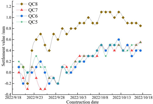
FIGURE 13. Cumulative displacement change of bridge pier measurement points.
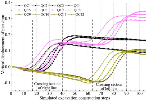
FIGURE 14. Variations in the displacement of bridge pier measurement points (numerical simulation).
From the analysis of Figure 14, the impact on the piers in the two laterally passing sections is significantly greater than the other stages, and for the left line laterally passing section, the secondary disturbance on the central piers No. 764 and No. 758 is obvious. From the analysis of the data in the figure, after the application of isolation piles, the impact of shield tunnel excavation of a single tunnel results in a pier displacement bulge of approximately 0.2 mm, and the impact of disturbance will be superimposed.
As shown in Figure 13, after the isolation piles were applied on site, the additional bridge pier uplift reached 0.6 mm when the right line excavation was carried out, after which the uplift tended to be stable, and then a gentle uplift change occurred when the left line excavation was carried out, indicating that the initial excavation disturbed the original stratum more, so during construction, special attention should be given to the control of the construction measures that change the initial stress field. During the preliminary lateral passing, several piers appeared to be bulging, with a maximum bulging value of 1.12 mm. Combined with the analysis of the site conditions, the shield advance speed should be controlled during the lateral passing of the piers, and the shield should be passed steadily and slowly. This measure can ensure that when the soil excavation advances unexpectedly or the piers settle abnormally, a timely response can be dealt with. When the advance speed is slow, the pressure and thrust of the soil bin increase, and the soil layer in front of the excavation are often in a passive soil pressure state. When the excavation speed is slow, the soil bin pressure and thrust increase, the layer in front of the excavation is often in a state of passive earth pressure, and the front side of the soil layer under the action of thrust becomes increasingly dense. At the same time, in the excavation process, synchronous subsurface grouting and surface grouting strengthen the surrounding soil layer so that the soil body exhibits a local up-lift phenomenon, which also makes the high-speed railway bridge piles slightly uplift.
When the shield tunneling was completed, the maximum vertical settlement of the bridge pier affected by excavation was 1.1 mm, and the settlement curve of each pier-bearing platform showed a trend of gradual increase. As the excavation proceeded, the magnitude of the settlement decreased until it reached a stable state. The site settlement monitoring and numerical simulation results meet the relevant requirements; at the same time, the measured settlement values at the site with many measurement points are greater than the numerical simulation results, but the difference between the numerical simulation and measured data is not large, indicating that the simulation calculation results are reliable.
6 Conclusion
Relying on a shield interval of a passing high-speed railway project in Xi’an, MIDAS GTS finite element calculation software was used to study the displacement characteristics of the high-speed railway piers, measurements, and simulations were conducted to analyze the settlement of the surrounding ground surface and piers, and the following conclusions were obtained.
(1) An isolation pile has a good control effect on the vertical displacement of a bridge pier. When an isolation pile is applied, the reduction in the vertical displacement of a corresponding bridge pier is 0.6 mm when the right line tunneling advances; when the left and right line tunnels are constructed simultaneously, the reduction in the vertical displacement reaches 1.1 mm; the isolation pile takes up most of the soil disturbance generated by the shield tunneling and reduces the change in the increase in the vertical displacement by isolating the development and stress path of the soil rupture surface.
(2) The vertical displacement of the ground surface is in the form of both uplift and settlement and exists at the same time; the unloading of soil caused by shield tunneling leads to the formation of a ground settlement trough on the top of the tunnel vault, transitioning from the “V” shape formed by the single-line boring of the right line to the “W” shape after the passage of the left and right lines. The settlement after the single-line and double-line boring when isolation piles are applied is not much different from that when isolation piles are not applied, but the application of isolation piles can effectively control the impact of tunnel boring excavation and significantly reduce its impact range.
(3) With the gradual progress of the excavation process, the lateral displacement pattern of the isolation pile changes regularly, the stress release of the soil layer is synchronized with the application of excavation pressure, the lateral uplift is maintained as a “double-C outward expansion shape”, and the vertical uplift is stabilized in the range of 1.2–1.6 mm. Due to the high mobility and poor self-stability of the water-rich sand layer, when the soil excavation-related stress is released, it is necessary to grout and perform other procedures in time to stabilize the sand layer deformation.
(4) The initial excavation has a great disturbance to the original stratum, and the increment of pier uplift reaches 0.6 mm during the single-line excavation. It is necessary to pay attention to the control of construction measures for the initial stress field, and strictly control the parameters such as the pressure of the mud tank and grouting pressure during tunneling to ensure the safety of the tunnel structure and the stability of the surrounding soil layer.
Data availability statement
The datasets presented in this study can be found in online repositories. The names of the repository/repositories and accession number(s) can be found in the article/Supplementary Material.
Author contributions
YT led the effort, developed tools, and performed analysis. LS completed numerical simulation and comparative analysis of data. ZH and LX assisted in field data collection and preliminary analysis.
Funding
This work was supported by the Key Research and Development Program of Shaanxi Province (No.2023YBSF516) and the Graduate Scientific Innovation Fund for Xi’an Polytechnic University(chx2023032).
Acknowledgments
We would like to thank AJE (www.aje.cn) for English language editing.
Conflict of interest
The authors declare that the research was conducted in the absence of any commercial or financial relationships that could be construed as a potential conflict of interest.
Publisher’s note
All claims expressed in this article are solely those of the authors and do not necessarily represent those of their affiliated organizations, or those of the publisher, the editors and the reviewers. Any product that may be evaluated in this article, or claim that may be made by its manufacturer, is not guaranteed or endorsed by the publisher.
References
Beyabanaki, A., and Gall, V. (2017). 3D numerical parametric study of the influence of open-pit mining sequence on existing tunnels. Int. J. Min. Sci. Technol. 27 (3), 459–466. doi:10.1016/j.ijmst.2017.03.018
Bilotta, E., and Russo, G. (2011). Use of a line of piles to prevent damages induced by tunnel excavation. J. geotechnical geoenvironmental Eng. 137 (3), 254–262. doi:10.1061/(ASCE)GT.1943-5606.0000426
Chen, R., Meng, F., Li, Z., Ye, Y., and Ye, J. (2016). Investigation of response of metro tunnels due to adjacent large excavation and protective measures in soft soils. Tunn. Undergr. Space Technol. 58, 224–235. doi:10.1016/j.tust.2016.06.002
Cheng, W., Song, Z., Tian, W., and Wang, Z. (2018). Shield tunnel uplift and deformation characterisation: A case study from zhengzhou metro. Tunn. Undergr. Space Technol. 79, 83–95. doi:10.1016/j.tust.2018.05.002
Dezi, F., Carbonari, S., Tombari, A., and Leoni, G. (2012). Soil-structure interaction in the seismic response of an isolated three-span motorway overcrossing founded on piles. Soil Dyn. Earthq. Eng. 41, 151–163. doi:10.1016/j.soildyn.2012.05.016
Fattah, M., Shlash, K., and Salim, N. (2013). Prediction of settlement trough induced by tunneling in cohesive ground. Acta Geotech. 8 (2), 167–179. doi:10.1007/s11440-012-0169-4
Huang, K., Sun, Y., Kuang, X., Huang, X., Liu, R., and Wu, Q. (2022). Study on the restraint effect of isolation pile on surface settlement trough induced by shield tunnelling. Appl. Sci. 12 (10), 4845. doi:10.3390/app12104845
Huang, K., Sun, Y., Zhou, D., Li, Y., Jiang, M., and Huang, X. (2021a). Influence of water-rich tunnel by shield tunneling on existing bridge pile foundation in layered soils. J. Central South Univ. 28 (8), 2574–2588. doi:10.1007/s11771-021-4787-6
Huang, X., Li, L., Zhang, C., Liu, B., Li, K., Shi, H., et al. (2021b). Multi-step combined control technology for karst and fissure water inrush disaster during shield tunneling in spring areas. Front. Earth Sci. 9, 795487. doi:10.3389/feart.2021.795457
Jia, M., Yan, Q., and Zhu, W. (2022). Case study: Influence of artificial mountain construction with isolation piles on underpass tunnels. Int. J. Civ. Eng. 2022, 193–203. doi:10.1007/s40999-022-00749-6
Liao, S., and Sangrey, D. (1978). Use of piles as isolation barriers. J. Geotechnical Eng. Div. 104 (9), 1139–1152. doi:10.1061/AJGEB6.0000684
Liu, K., Xu, X., Hu, Q., Zeng, L., and Wang, J. (2022). 1g model test on the use of isolation piles for tunnel protection adjacent to soft soil excavation. Transp. Geotech. 35, 100790. doi:10.1016/j.trgeo.2022.100790
Lv, J., Li, X., Li, Z., and Fu, H. (2020). Numerical simulations of construction of shield tunnel with small clearance to adjacent tunnel without and with isolation pile reinforcement. KSCE J. Civ. Eng. 24 (1), 295–309. doi:10.1007/s12205-020-1167-y
Ma, H., Yin, L., Gong, Q., and Wang, J. (2015). TBM tunneling in mixed-face ground: Problems and solutions. Int. J. Min. Sci. Technol. 25 (4), 641–647. doi:10.1016/j.ijmst.2015.05.019
Ma, S., Fu, X., Lu, H., Huang, Z., and Zhang, J. (2021). A combined support method of isolation pile and diaphragm wall for protection of buildings adjacent to deep foundation pit. Arabian J. Geosciences 14 (19), 2005–2012. doi:10.1007/s12517-021-08345-z
Pan, Y. H., Qi, J. R., Zhang, J. F., Peng, Y. X., Chen, C., Ma, H. N., et al. (2022). A comparative study on steady-state water inflow into a circular underwater tunnel with an excavation damage zone. Water 14 (19), 3154. doi:10.3390/w14193154
Qiu, H., Wang, Z., Ayasrah, M., Fu, C., and Gang, L. (2022). Numerical study on the reinforcement measures of tunneling on adjacent piles. Symmetry 14 (2), 288. doi:10.3390/sym14020288
Ren, S., Zhao, Y., Liao, J., Liu, Q., and Li, Y. (2022). Lugeon test and grouting application research based on RQD of grouting sections. Sustainability 14 (19), 12748. doi:10.3390/su141912748
Shan, Y., Cheng, G., Gu, X., Zhou, S., and Xiao, F. (2021). Optimization of design parameters of displacement isolation piles constructed between a high-speed railway bridge and a double-line metro tunnel: From the view point of vibration isolation effect. Comput. Geotechnics 140, 104460. doi:10.1016/j.compgeo.2021.104460
Song, Q. (2021). Study on control measures of the influence of shallow buried tunnel excavation on the subgrade settlement of high-speed railway in operation. Vibroengineering Procedia 36, 37–42. doi:10.21595/vp.2021.21900
Wei, G., Qi, Y., Chen, C., Zhang, S., Qian, C., and Zhou, J. (2022). Analysis of the protective effect of setting isolation piles outside the foundation pit on the underpass tunnel side. Transp. Geotech. 35, 100791. doi:10.1016/j.trgeo.2022.100791
Weng, G., Xie, Q., Xu, C., Zhang, P., and Zhang, X. (2023). Seismic response of cable-stayed spanning pipeline considering medium-pipeline fluid–solid coupling dynamic effect. Processes 11 (2), 313. doi:10.3390/pr11020313
Wu, H., Jia, Q., Wang, W., Zhang, N., and Zhao, Y. (2021). Experimental test on nonuniform deformation in the tilted strata of a deep coal mine. Sustainability 13 (23), 13280. doi:10.3390/su132313280
Xiang, Y., Jiang, Z., and He, H. (2008). Assessment and control of metro-construction induced settlement of a pile-supported urban over-pass. Tunn. Undergr. Space Technol. 23 (3), 300–307. doi:10.1016/j.tust.2007.06.008
Yao, A., Lu, J., Guo, Y., Zhang, J., and Guo, H. (2019). Reinforcement effects of isolation piles on the adjacent existing tunnel in building construction. Adv. Mater. Sci. Eng. 2019, 1–21. doi:10.1155/2019/9741306
Yao, A., Yang, X., and Dong, L. (2012). Numerical analysis of the influence of isolation piles in metro tunnel construction of adjacent buildings. Procedia Earth Planet. Sci. 05, 150–154. doi:10.1016/j.proeps.2012.01.026
Yu, W., Li, K., Liu, Z., An, B., Wang, P., and Wu, H. (2021). Mechanical characteristics and deformation control of surrounding rock in weakly cemented siltstone. Environ. Earth Sci. 80, 337–415. doi:10.1007/s12665-021-09626-2
Yuan, Z., Zhao, J., Li, S., Jiang, Z., and Huang, F. (2022). A unified solution for surrounding rock of roadway considering seepage, dilatancy, strain-softening and intermediate principal stress. Sustainability 14 (13), 8099. doi:10.3390/su14138099
Zhang, C., Zhao, Y., Zhang, Z., and Zhu, B. (2021). Case study of underground shield tunnels in interchange piles foundation underpinning construction. Appl. Sci. 11 (4), 1611. doi:10.3390/app11041611
Zhang, P., Pan, Y., Yu, Z., Guan, X., Wang, G., An, J., et al. (2020). Ground subsidence characteristics caused by construction of shallow-buried tunnel in a sandy soil composite formation. Arabian J. Geosciences 13 (18), 901–913. doi:10.1007/s12517-020-05880-z
Zhang, Q., Zhu, Y., Ma, R., Du, C., Du, S., Shao, K., et al. (2022b). Prediction method of TBM tunneling parameters based on PSO-Bi-lstm model. Front. Earth Sci. 10, 854807. doi:10.3389/feart.2022.854807
Zhang, Z., Zhao, C., Peng, L., Zhang, X., and Lei, M. (2022a). Research on the stability of shallow-buried large cross-section tunnel by construction method conversion. Front. Earth Sci. 10, 831169. doi:10.3389/feart.2022.831169
Keywords: shield tunnel, existing high-speed railway, isolation pile, numerical simulation, short-distance passing
Citation: Tao Y, Shuailei L, Hao Z and Xingru L (2023) Study on the restraint control of an isolation pile on an existing high-speed railway during the close passing of a shield machine. Front. Earth Sci. 11:1142864. doi: 10.3389/feart.2023.1142864
Received: 12 January 2023; Accepted: 14 March 2023;
Published: 23 March 2023.
Edited by:
Junbao Wang, Xi’an University of Architecture and Technology, ChinaReviewed by:
Xing Zhao, Yellow River Institute of Hydraulic Research, ChinaShu Yu, China Institute of Water Resources and Hydropower Research, China
Copyright © 2023 Tao, Shuailei, Hao and Xingru. This is an open-access article distributed under the terms of the Creative Commons Attribution License (CC BY). The use, distribution or reproduction in other forums is permitted, provided the original author(s) and the copyright owner(s) are credited and that the original publication in this journal is cited, in accordance with accepted academic practice. No use, distribution or reproduction is permitted which does not comply with these terms.
*Correspondence: Yang Tao, eWFuZ3Rhb0B4cHUuZWR1LmNu