 Xueqiang Zhang1
 Shuang Cai
 Feng Yang
- 1Qinghai Communications Construction Management Co., Ltd., Xining, Qinghai, China
- 2China Merchants Chongqing Communications Technology Research and Design Institute Co., Ltd., Chongqing, China
- 3Sichuan Highway Planning, Survey, Design and Research Institute Ltd., Chengdu, Sichuan, China
The air density in high altitude gas tunnel is small and the air supply is difficult. The jet tunnel ventilation is a common construction ventilation mode. In order to explore the pollutant distribution characteristics and the optimal ventilation length of tunnel ventilation in high altitude gas tunnel, Ningchan tunnel has been taken as the engineering background, the fluid dynamics software Fluent has been used to establish a three-dimensional model of jet tunnel ventilation, the distribution characteristics of methane, hydrogen sulfide and other harmful gas in the tunnel have been studied, and the optimal ventilation length of tunnel ventilation in high altitude gas tunnel degree has been explored. The results show that: the minimum ventilation length required in the existing technical specifications of gas tunnel is not reasonable, which leads to the existence of low-speed wind area in the tunnel, and harmful gas is easy to gather in the single head section, and the gas concentration can reach 0.59% at 2 m away from the working face; by reducing the ventilation length, the gas concentration in the single head section can be effectively reduced, and when the ventilation length is 1,200 m, the gas concentration at 2 m away from the working face will be reduced to 0.31%; setting local fan in front of the roadway can also significantly improve the accumulation degree of harmful gas in the single end section. The maximum gas concentration of working face reduced to 0.24%, and the average gas concentration of reduced to 0.15%. The results can provide reference for ventilation scheme of high altitude gas tunnel construction.
1 Introduction
Accelerating the traffic construction in West China and deepening the connection between the inland and West China are the inevitable requirements of the China Western Development and the “Belt and Road Initiative.” The western region of China is located on the first gradient and has a generally high altitude, above 4,000 m on average. The continuous efforts of scientific researchers to overcome extreme conditions such as extreme coldness and frozen soil has made China a world leader in high-altitude tunnel construction technology, bringing China’s tunnel construction technology to a new level (Hegeng et al., 2017; Lin, 2017). When a tunnel passes through a layer containing harmful gas, the methane, hydrogen sulfide and other toxic and harmful gas gushing from the tunnel face seriously threaten the construction safety. In order to improve the working environment of tunnel construction and ensure the health of operating personnel, effective ventilation measures must be taken (Wang et al., 2018; Gao et al., 2021). Especially for special dangerous tunnels with the presence of toxic and harmful gas such as gas and hydrogen sulfide, proper ventilation and wind speed must be ensured to dilute the toxic and harmful gas in time, so as to prevent casualties and explosion accidents caused by accumulation of toxic and harmful gas (Li et al., 2020).
The ventilation modes of highway tunnels generally include forced ventilation, exhaust ventilation, compound ventilation and gallery ventilation (Cheng et al., 2021; Liu et al., 2021). Gallery ventilation scheme is mostly used for long tunnels. There have been many researches on gallery ventilation technology at home and abroad, and some achievements have been made (Wang and Qiu, 2015; Wu, 2018; Li, 2020). The existing ventilation scheme is generally modeled based on ordinary long tunnels, or by only taking account of the influence of methane, hydrogen sulfide, dust and other single factors on ventilation, and then calculating the air demand, to determine the fan selection and field equipment layout (Wang, 2016; Chun et al., 2019; He, 2019), without considering the influence of complex construction environment such as extreme coldness and high altitude on the implementation of ventilation scheme during tunnel construction. For high-altitude gas tunnels, under the condition of low pressure and insufficient oxygen, the air supply efficiency of fans is low, and it is easy to cause gas accumulation in the low wind speed area of the tunnel (Luo et al., 2020). Therefore, the ventilation of gas tunnel construction in high altitude areas is facing severe challenges. It is of great significance to study the characteristics of the ventilation of gas tunnel construction in high altitude areas and explore the technical scheme of ventilation in gas tunnel construction at high altitudes for improving the air quality in tunnels, ensuring the health of operating personnel at the tunnel face and guaranteeing the normal operation of construction equipment.
Ningchan Tunnel, the longest high-altitude highway tunnel in Qinghai Province, is the control project of Ningchan Pass-Ketu Section of National Highway 569 between Mandela and Datong. Taking Ningchan Tunnel as an example, this paper, through field investigation and analysis of the tunnel construction ventilation, simulates the gallery ventilation network during the construction period by using Fluent numerical software, collects the field measured data, verifies the accuracy of the calculation model, analyzes the distribution law of methane and hydrogen sulfide in gallery ventilation of high-altitude tunnels, and puts forward the optimal design length of gallery ventilation, to provide reference for the construction ventilation of high-altitude extra-long gas tunnels.
2 Project overview
2.1 Surrounding rock geology
Ningchan Tunnel is a four-lane Class I highway tunnel with separated up and down traffic, which is located in the middle and high mountain landform area of tectonic denudation. The middle and rear sections of Ningchan Tunnel pass through the interbedded layers of moderately and highly weathered carbonaceous shale (containing coal line) and sandstone. Drilling exploration shows that the gas content of coal samples is between 0.06 and 1.67 m3/t, the percentage of CH4 is less than 10%, and the gas content per ton of coal in the tunnel area is less than 8 m3/t, accompanied by hydrogen sulfide gas emission, which is a high gas tunnel, as shown in Figure 1. In the tunnel area, the maximum sea-level elevation is 4,122.0 m, the minimum elevation is 3,460.00 m, and the annual average temperature is 0.8°C.
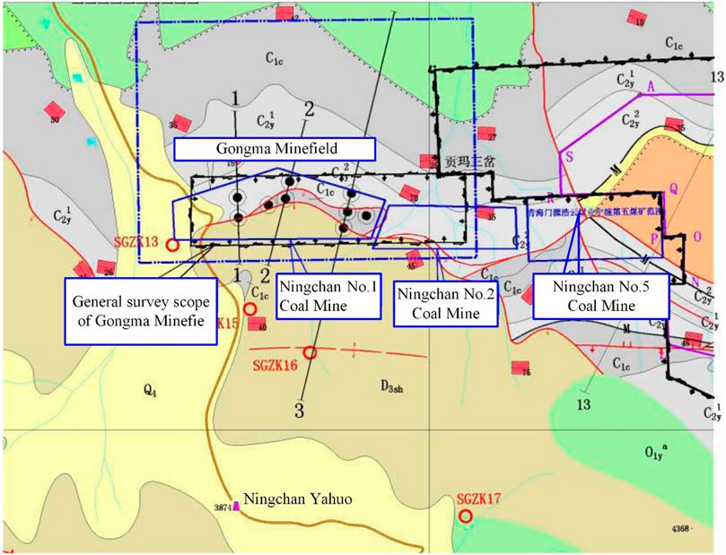
FIGURE 1. Geological plan.
The tunnel is an extra-long tunnel. In order to ensure the safety in the operation stage, a vehicle adit connecting the two vehicular tunnels is set at an interval of 750 m between the left and right caverns, and the vehicle adits are arranged perpendicular to the main tunnels. Emergency parking strips with a length of 40 m are set with the vehicle adit as the midpoint, and two pedestrian adits are set between the two vehicle adit to connect the two main tunnels. At present, the length of tunnel excavated is 1,060 m. Each section is shown in Figure 2.
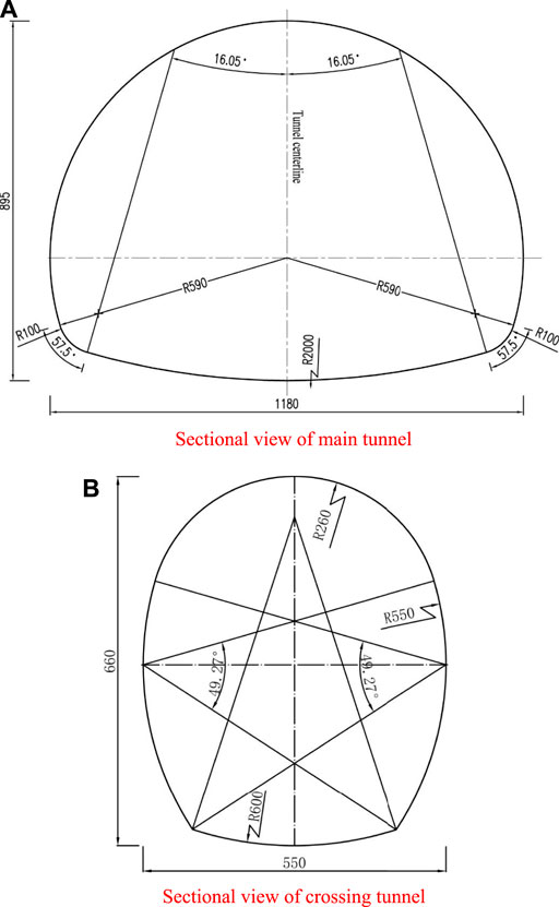
FIGURE 2. Sectional view of Ningchan Tunnel. (A) Sectional view of main tunnel. (B) Sectional view of crossing tunnel.
2.2 Construction ventilation
The tunnel is very long. If forced ventilation and exhaust ventilation are adopted, there will be problems such as overlong air duct, excessive wind resistance and high energy consumption. Therefore, jet gallery ventilation is adopted in the construction process (Sun, 2018; Li, 2019). In the parallel double-tube tunnel, the tunnel portal on the right side is taken as the fresh air tunnel of the ventilation system, and the fresh air is introduced by jet fan. When flowing to the vicinity of the transverse passage, the fresh air is sent to the left and right working faces by the axial fans combined with the air supply ducts to dilute the pollutants. The dirty air on the air-in side flows back from the working face to the tunnel on the return air side through the transverse passage, joins the dirty air from the working face on the return air side, and is finally exhausted from the tunnel portal on the return air side. The specific arrangement is shown in Figure 3.
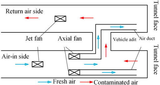
FIGURE 3. Schematic diagram of tunnel jet gallery ventilation.
3 Numerical model
3.1 Mathematical equations
During the excavation of the tunnel, the gas (hydrogen sulfide) gushes out directly from the working face being excavated have been assumed, and there are two stages during removing or diluting gas (hydrogen sulfide) by jet gallery ventilation:
1. Air-gas (hydrogen sulfide) convection.
2. Turbulent diffusion of gas (hydrogen sulfide) caused by turbulent air flow.
The governing equation of the mathematical model for the turbulent diffusion of gas (hydrogen sulfide) is: continuity equation, momentum equation, energy equation and component transport equation. The turbulence model adopts double-equation turbulence model, and near-wall flow is treated by wall function method. As the density of gas (hydrogen sulfide) is different from that of air, the influence of buoyancy lift should be considered in simulation.
3.1.1 Continuity equation
Where, ρ is the air density (kg/m3); ui is the velocity component (m/s); and xi is the coordinate axis direction (i = 1, 2, 3).
3.1.2 Momentum equation
Where, p is the air pressure (Pa); k is the turbulence pulsation kinetic-energy of fluid per unit mass,
3.1.3 Energy equation
Where, T is the air temperature (K); Pr is the Prandtl number at full turbulence; q is the heat flux (W/m2); and cp is the constant-pressure specific heat of air J/(kg.K).
3.1.4 Component transport equation
Where, c is the volume concentration of substance component η (%); D is the diffusion coefficient of substance component (m2/s); k is the heat transfer coefficient [w/(m2.k)]; and ST is the generation rate of components per unit time (J).
3.1.5 Turbulence model
The k-ε double-equation turbulence model is used for numerical calculation, where the expression of Reynolds stress is:
Where, each physical quantity is time weighted average, διφ is Kronecker symbol, and the value is 1 when i = j; otherwise it is 0.
The calculation expression of turbulent viscosity coefficient is:
Where, C is empirical coefficient and ε is the dissipation rate of pulsation kinetic-energy per unit mass of fluid,
Where, C1, C2, σk and σε are all empirical coefficients. Eqs 6–8 jointly constitute the k-ε double-equation turbulence model, and the coefficient in the model is constant.
3.2 Physical model and boundary conditions
Taking the actual size of Ningchan Tunnel as reference, the 3D model of jet gallery ventilation is established by AutoCAD. The selected size is: length of simulated tunnel: 1,500 m; air supply duct diameter: 1.5 m; air duct height: 3.5 m; distance from air duct opening to tunnel face: 10 m. The 3D model is shown in Figure 4. Grid generation has an important impact on the accuracy of the calculation results. Accurate hexahedron structure grid division is made in the ICEM-CFD software to ensure that the grid can adapt to the geometric model well, and the grid is locally infilled to further improve the quality of the grid and ensure the accuracy of the calculation. The total number of grids of each model is about 2.85 million, so the grid division quality is high, which can provide reliable guarantee for the following numerical calculation.
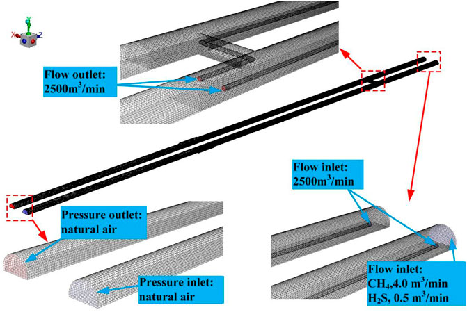
FIGURE 4. 3D model of computational domain.
The outlet of the air supply duct is set as the inlet boundary, the type is Mass-Flow-Inlet, Q = 2,785 m3/min and the air supply temperature is 0.8°C. The inlet of the air supply duct is set as the outlet boundary, the type is Mass-Flow-Outlet, and the flow rate is the same as the air outlet. The right tunnel portal (air intake) is set as the inlet boundary, the type is Pressure-Inlet; the left tunnel portal (return air side) is set as the inlet boundary, the type is Pressure-Outlet. And the back pressure is local (high altitude) atmospheric pressure (70.20 kpa), and the temperature is the same as the air temperature.
The boundary types of tunnel wall and air duct wall are rigid wall boundary, with wall roughness of 0.022 and temperature of 27°C. Gas (hydrogen sulfide) source is set in the working face area of the right tunnel, and the gas (hydrogen sulfide) source terms, including quality source term and momentum source term, are set according to the gas (hydrogen sulfide) emission amount. The momentum source term only considers the direction momentum, with gas emission amount of 4.0 m3/min and hydrogen sulfide emission amount of 0.5 m3/min, as shown in Figure 4. For the turbulent diffusion flow field of gas (hydrogen sulfide), the pressure-velocity coupling SIMPLE method and the k-ε double-equation turbulence model are used for analysis. According to the gallery ventilation system and design requirements, the convergence judgment condition is that the residual error of all physical quantities is less than 1.0E-3.
3.3 Verification of simulation results
When gallery ventilation is adopted, the gas concentration on the return air side is relatively high, so six measuring points are arranged equidistantly at 20–200 m away from the tunnel face on the return air side. In different periods of tunnel construction, the concentration is tested at each measuring point for 3 times to obtain the average values, and compared with the simulation results, as shown in Figure 5. The average values of the measured gas concentration at the six measuring points in the tunnel are 0.19%, 0.16%, 0.14%, 0.14%, 0.13%, and 0.13%, respectively, and the simulated values are 0.20%, 0.17%, 0.14%, 0.13%, and 0.13%, respectively. The average relative error between measured and calculated values is only 3.6%. It can be seen that the calculation accuracy of the model is high, and it can be competent for simulation calculation and parameter optimization.
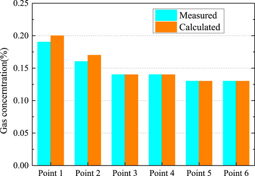
FIGURE 5. Comparison between measured data and simulation results.
4 Distribution characteristics of harmful gas
4.1 Overall distribution
The horizontal plane with a height of 2 m (pedestrian height) is selected for observation. The overall distribution of gas and hydrogen sulfide in the tunnel is shown in Figures 6, 7. It can be seen from the figures that the area with the highest toxic and harmful gases is at the tunnel face, with the highest reaching 0.93% and 0.11%, respectively. Gas and hydrogen sulfide concentrations have exceeded the limits of 0.5% and 6.6 ppm. Because the air duct continues to supply air to the tunnel face, there is also areas with low concentration near the tunnel face. The concentration of gas and hydrogen sulfide from the tunnel face to the transverse passage is relatively high, which is 0.31% and 0.03% respectively, and the distribution is relatively uniform. There is no gas or hydrogen sulfide from the right line entrance to the transverse passage. This is because the right line of this gallery ventilation system is the inlet side, and the left line is the outlet side. From the right line entrance to the transverse passage, there is fresh air from outside the tunnel flowing to the transverse passage, where the fresh air mixes with the polluted air exhausted from the right line tunnel face and flows to the left line tunnel, as shown in Figure 8. In the transverse passage, the concentration of gas and hydrogen sulfide is low and unevenly distributed, which is caused by the mixing of the fresh air and the polluted air. The concentrations of gas and hydrogen sulfide from the left line outlet to the transverse passage are low, with an average of 0.34% and 0.04%, respectively.
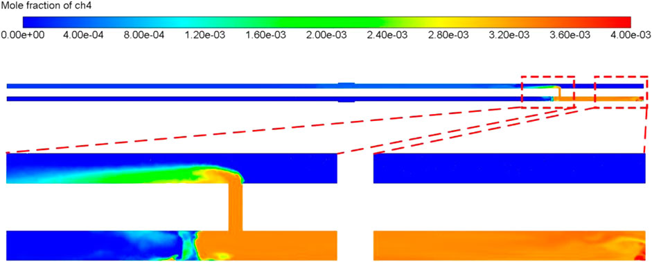
FIGURE 6. Overall concentration distribution of gas.
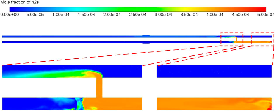
FIGURE 7. Overall concentration distribution of hydrogen sulfide.
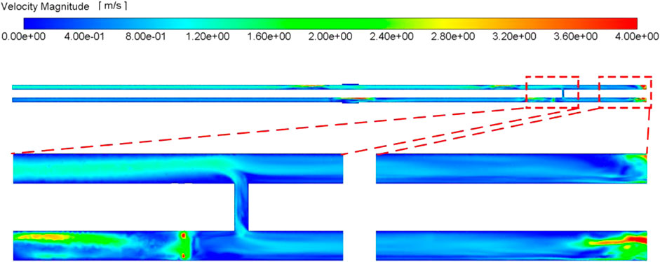
FIGURE 8. Air velocity distribution nephogram.
Figure 9 shows the change curve of gas concentration on the axis of the right line (air-in side) and the left line (return air side) of the tunnel at a height of 2 m. It can be seen from the figure that the distance 200 m away from the tunnel face (where the transverse passage is located) is the boundary of alternating gas concentration in the tunnel, which is also a prominent feature of gallery ventilation. Analysis: when the distance from the tunnel face is less than 50 m, the gas concentration in the tunnel fluctuates greatly, and the gas concentration reaches the maximum value of 1.04% within 20 m from the tunnel face; when the distance from the tunnel face is 50–200 m, the gas is evenly mixed with the fresh air supplied by the fan at the inlet side, and the average concentration is 0.71%; when the distance from the tunnel face is 200–400 m, the polluted air on the air-in side is mixed with the fresh air flow supplied by the fan on the return air side through the transverse passage, so the average gas concentration gradually decreases from the tunnel face to the tunnel portal; and when the distance from the tunnel face is more than 400 m, the gas has been mixed with the air again and exhausted out of the tunnel with the air flow, and the gas concentration is 0.33%.
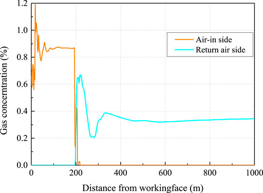
FIGURE 9. Change curve of longitudinal average gas concentration in tunnel.
From the overall analysis of gallery ventilation, it can be seen that on the air-in side, most of the fresh air supplied from outside the tunnel does not reach the tunnel face, but directly reaches the exhaust tunnel through the transverse passage, which is not fully utilized. Therefore, it is very important to optimize the design of gallery ventilation and improve the air supply from outside the tunnel to the tunnel face, instead of only taking the total ventilation as the evaluation index.
4.2 Local distribution
Methane distribution in tunnel section 2 m away from the tunnel face is shown in Figure 10A. This section is an area where operating personnel have many activities, and it is also the most dangerous area affected by harmful gas. The methane concentration on the right side of the tunnel section is the lowest, only 0.29%, while that on the left side is the highest, with the maximum concentration reaching 2.9%. This is mainly due to the fact that the upper right corner is directly in front of the air duct, and the emitted methane is taken away by the high-speed airflow, while the wind speed in the lower right corner is the smallest, which cannot effectively disperse methane, as shown in Figure 10B. It can be said that wind speed has great influence on the accumulation of methane.
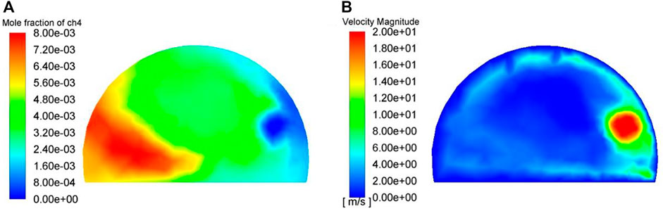
FIGURE 10. Gas distribution nephogram and velocity nephogram at tunnel face. (A) Gas distribution nephogram at tunnel face. (B) Velocity nephogram at tunnel face
The distribution of methane at the transverse passage is shown in Figure 11A. The section is located in the middle of the transverse passage, and the distribution of methane concentration is small on the right side and large on the left side, with the maximum concentration of 0.71%, slightly lower than that at the tunnel face. This is mainly due to the suppression of fresh air flow on the air-in side, and the polluted air at the tunnel face flows from the transverse passage near the tunnel face side, resulting in the accumulation of gas on the left side far away from the tunnel face, as shown in Figure 11B.
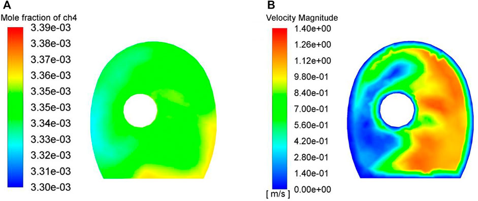
FIGURE 11. Gas distribution nephogram and velocity nephogram at transverse passage. (A) Gas distribution nephogram at transverse passage. (B) Velocity nephogram at transverse passage
The yard gas distribution on the return air side is shown in Figure 12A. This section is located between the transverse passage on the return air side and the tunnel exit. The methane concentration is high at the upper part and low at the lower part, with the maximum concentration of 0.34%. The main reason for this is that the density of methane is smaller than that of air, so it will accumulate upward when the wind speed is low. Especially for suddenly enlarged sections such as widened section, the wind speed distribution is uneven, and the wind speed at the top is lower, which is more conducive to gas accumulation, as shown in Figure 12B.
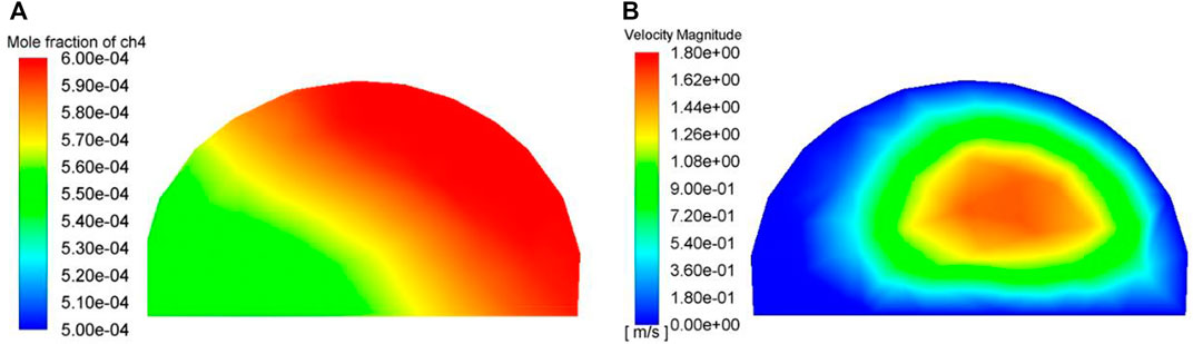
FIGURE 12. Gas distribution nephogram and velocity nephogram at widened section of return air side. (A) Gas distribution nephogram at widened section of return air side. (B) Velocity nephogram at widened section of return air side.
5 Optimization and application of ventilation length
5.1 Optimization of ventilation length
According to the above research, the key of gallery ventilation at high altitudes is to form positive return air flow to exhaust harmful gas. The key factor is the length of gallery. If the gallery is too long, the ventilation resistance will increase, which will affect the return flow, and even cause a reverse flow. In addition, according to the analysis of local flow field and methane distribution, there is a low wind speed area between the tunnel face and the transverse passage, and the wind speed in this area is lower than the minimum allowable wind speed by 0.5 m/s, which is not conducive to the emission of gas and other toxic and harmful gas in the tunnel. To improve the wind speed in this area and reduce the possibility of harmful gas accumulation, it is necessary to optimize the construction ventilation. Generally, there are two ways to solve this problem: one is to reduce the ventilation length, and the other is to set up local fans in areas with low wind speed (Lei et al., 2019; Yao et al., 2021). Therefore, a calculation model is established for tunnels with different construction lengths to simulate the effects of different ventilation lengths on gallery ventilation, and the improvement effect of setting local fans on air flow is also investigated.
According to the requirements of the Specifications for Design and Construction of Highway Tunnels with Gas (JTG/T 3374-2020), it is recommended that the design length of gallery ventilation for tunnels should not exceed 1,500 m at present. However, according to the above analysis, the construction ventilation of high-altitude tunnels is characterized by low air pressure, insufficient oxygen and large ventilation resistance, so if the design value of ordinary altitude tunnels is used, it may be on the high side. Reducing the ventilation length can effectively reduce the airflow friction and improve the accumulation of harmful gas in tunnel. We set the ventilation length to 1,100, 1,200, 1,300, and 1,400 m respectively, and then conduct recalculation for these working conditions. The gas concentration distribution of the section near the tunnel face on the air-in side (0–200 m away from the working face) and the section far from the tunnel face on the return air side (200–1,000 m away from the working face) in the tunnel is shown in Figure 13. It can be seen from the figure that reducing the ventilation length can effectively reduce the gas concentration in the tunnel. When the ventilation length is 1,200 m, more air is supplied to the tunnel face, the fluctuation of gas concentration at the tunnel face is small, and the highest gas concentration at the tunnel face can be reduced to 0.73%, but the gas concentration in the polluted air at the return air side has little change. Therefore, when the ventilation length is 1,200 m, the accumulation of harmful gas, such as gas and hydrogen sulfide, on the tunnel face will be effectively relieved, and the fresh air from outside the tunnel can be fully utilized, thus reducing waste.
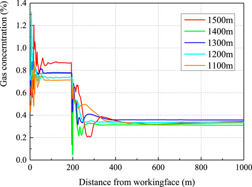
FIGURE 13. Longitudinal gas concentration distribution of tunnels with different design lengths.
In addition, the method of setting local fans at the tunnel face and the transverse passage to increase the wind speed in the low-speed area can also increase the fresh air volume supplied to the tunnel face. Local fans are often used to disperse and dilute toxic and harmful gas such as methane and hydrogen sulfide during construction. According to the analysis of pollutant distribution characteristics in the previous section, the wind speed on the left side of the transverse passage far from the tunnel face is the lowest, which is prone to gas accumulation. Therefore, a local fan is set on the left side of the transverse passage in the model. The calculated gas concentration distribution in the polluted air section of the tunnel with local fans is shown in Figure 14. After setting local fans, the gas concentration at the transverse passage (200 m away from the working face) is significantly improved, the highest gas concentration at the tunnel face is reduced to 0.69%, and the gas concentration in the polluted air at the return air side is reduced to 0.27%. This is mainly due to the fact that local fans increase the ventilation volume in the tunnel, especially in the low-speed area of the transverse passage, which greatly reduces the possibility of harmful gas accumulation in the tunnel.
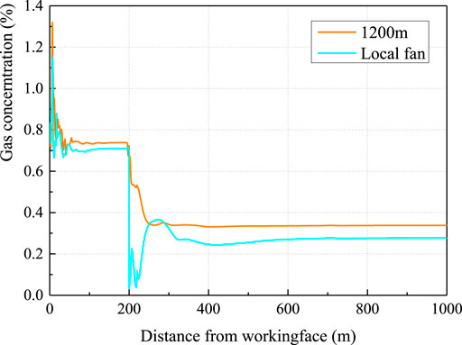
FIGURE 14. Comparison of gas concentration before and after setting local fans when the ventilation length is 1,200 m.
5.2 Application
According to the optimization results, the original ventilation length was reduced from 1,500 to 1,200 m, and local fans were set at the tunnel face and transverse passage. A gas concentration sensor was set at 2 m away from the tunnel face to monitor the changes in gas concentrations before and after the measures are taken in real time, as shown in Figure 15. Before the modification of ventilation mode, the gas concentration at the tunnel face was 0.35% on average and exceeded the limited concentration of 0.5% many times. After the modification of ventilation mode, the average gas concentration in the tunnel face quickly decreased to 0.16%, and no out-of-limit occurred. The field experiment demonstrates the effectiveness of ventilation measures, and the mean and maximum values are consistent with the numerical simulation results, which also verifies the reliability of numerical calculation.
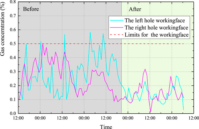
FIGURE 15. Measured values of gas concentrations before and after the change of field ventilation mode.
6 Conclusion
(1) A high-altitude tunnel construction ventilation model is established by Fluent software, and the distribution characteristics of harmful gas are analyzed. The simulation results show that the gas concentration distribution in the tunnel is consistent with the measured value, and the deviation is less than 3.6%, which indicates that the accuracy of the simulation calculation model can meet the ventilation design requirements of high-altitude tunnels.
(2) High-altitude tunnel construction ventilation is characterized by low air pressure, insufficient oxygen, large ventilation resistance, etc. The minimum ventilation length of 1,500 m required in the existing technical specification for tunnels with gas is unreasonable, which leads to the existence of low-speed wind areas in the tunnel, and harmful gas are easy to gather in the blind heading section of the working face. The maximum gas concentration reaches 0.59% and the average gas concentration is 0.34% at a position 2 m away from the working face.
(3) The gas concentration in the blind heading section can be effectively reduced by reducing the ventilation length. When the ventilation length is 1,200 m, the maximum gas concentration at 2 m away from the working face will be reduced to 0.31% and the average gas concentration will be reduced to 0.24%. Setting local fans in front of a carriageway can also significantly improve the concentration degree of harmful gas in the blind heading section, and the highest gas concentration in the working face is reduced to 0.15%.
Data availability statement
The original contributions presented in the study are included in the article/supplementary material, further inquiries can be directed to the corresponding authors.
Author contributions
XZ: review and editing, Investigation. JH: review and editing. DZ: Writing and Investigation. SC—review, editing and Investigation. FY: review and editing. All authors listed have made a substantial, direct, and intellectual contribution to the work and approved it for publication.
Funding
This work was supported by the Chongqing Natural Science Foundation (Distinguished Youth Fund) Project (No. cstc2021jcyjjqX0012), the Qinghai Provincial Science and Technology Plan (No. 2023-SF-128), and the Qinghai Transportation Science and Technology Project (No. 2020-01).
Conflict of interest
Authors XZ and DZ were employed by Qinghai Communications Construction Management Co., Ltd. Authors JH and SC were employed by China Merchants Chongqing Communications Technology Research and Design Institute Co., Ltd. Author FY was employed by Sichuan Highway Planning, Survey, Design and Research Institute Ltd.
Publisher’s note
All claims expressed in this article are solely those of the authors and do not necessarily represent those of their affiliated organizations, or those of the publisher, the editors and the reviewers. Any product that may be evaluated in this article, or claim that may be made by its manufacturer, is not guaranteed or endorsed by the publisher.
References
Cheng, Y., Zhang, X., Lu, Z., Pan, Z., Zeng, M., Du, X., et al. (2021). The effect of subcritical and supercritical CO2 on the pore structure of bituminous coals. J. Nat. gas Sci. Eng. 94, 104132. doi:10.1016/j.jngse.2021.104132
Chun, L., Du, J., and Guo, C. (2019). Influence of air duct arrangement on gas concentration in the large-section gas tunnel [J]. Mod. Tunn. Technol. 56 (05), 114–121.
Gao, M., Xie, J., Gao, Y., Wang, W., Li, C., Yang, B., et al. (2021). Mechanical behavior of coal under different mining rates: A case study from laboratory experiments to field testing. Int. J. Min. Sci. Technol. 31, 825–841. doi:10.1016/j.ijmst.2021.06.007
He, C. (2019). Study on Construction ventilation scheme of the extra-long and high gas-bearing tunnel on Dali (Lijiang) to Panzhihua Railway [J]. Mod. Tunn. Technol. 56 (S2), 478–484.
Hegeng, H., Zhijun, S., and Sheng, Pi (2017). Technical key points and mechanization matching of menghua railway tunnel construction [J]. Tunn. Constr. 37 (12), 1564–1570.
Lei, S., Fang, Y., and Liu, J. (2019). Research of construction ventilation optimization for Huayingshan tunnel on Nanchong-Dazu-Liangping Expressway [J]. Mod. Tunn. Technol. 56 (2), 194–200.
Li, H. (2019). Study on distribution characteristics of gas concentration in gas tunnel [J]. Highw. Eng. 44 (05), 216–220.
Li, J., Su, P., and Xu, Z. (2020). Study on shield construction technology of non-coal high gas tunnel [J]. Chin. J. Undergr. Space Eng. 16 (S1), 194–200.
Li, Z. (2020). Study on construction ventilation simulation of high gas, long and large tunnel [J]. China Energy Environ. Prot. 42 (08), 81–85.
Lin, Z. (2017). Analysis of construction quality control of roadbed settlement caused by highway embankment [J]. Highw. Eng. 42 (01), 156–159.
Liu, S., Li, P., and Li, S. (2021). Numerical simulation research on safe rock pillars of crosscut uncovering coal in highway tunnel [J]. China Energy Environ. Prot. 43 (03), 183–187+192.
Luo, Y., Wang, Y., and Song, X. (2020). Numerical simulation of construction ventilation resistance loss along the curved tunnel [J]. Chin. J. Undergr. Space Eng. 16 (S2), 897–903.
Sun, L. (2018). Ventilation scheme for construction of high-altitude gas tunnel [J]. Road Mach. Constr. Mech. 35, 130–136.
Wang, J. (2016). Roadway ventilation design and effect test in highway long tunnel construction [J]. Green Transp. (14), 178–179.
Wang, S., and Qiu, J. (2015). Study on ventilation technology of circulating tunnel in parallel double-hole long gas tunnel [J]. Bridge Tunn. Eng. 3, 230–232+309.
Wang, X., Wen, Z.-J, Jiang, Y., and Huang, H. (2018). Experimental study on mechanical and acoustic emission characteristics of rock-like material under non-uniformly distributed loads. J], Rock Mech. Rock Eng. 51 (03), 729–745. doi:10.1007/s00603-017-1363-3
Wu, J. (2018). Research on construction ventilation technology of zhegushan high gas tunnel [D]. Southwest Jiaotong University.
Keywords: high altitude, gas tunnel, harmful gas, tunnel ventilation, ventilation length
Citation: Zhang X, Hu J, Zhang D, Cai S and Yang F (2023) Distribution of harmful gas and ventilation length design of high altitude long gas tunnel construction: a case study. Front. Earth Sci. 11:1195880. doi: 10.3389/feart.2023.1195880
Received: 29 March 2023; Accepted: 09 May 2023;
Published: 19 May 2023.
Edited by:
Yubing Liu, China University of Mining and Technology, ChinaReviewed by:
Fei Huang, Hunan University of Science and Technology, ChinaXuelong Li, Shandong University of Science and Technology, China
Copyright © 2023 Zhang, Hu, Zhang, Cai and Yang. This is an open-access article distributed under the terms of the Creative Commons Attribution License (CC BY). The use, distribution or reproduction in other forums is permitted, provided the original author(s) and the copyright owner(s) are credited and that the original publication in this journal is cited, in accordance with accepted academic practice. No use, distribution or reproduction is permitted which does not comply with these terms.
*Correspondence: Danfeng Zhang, MzI4NjI0MTY0QHFxLmNvbQ==; Shuang Cai, Y2Fpc2h1YW5nQGNtaGsuY29t