 Di Hou
 Mengchao Xu1,2,3*
 Xiaoshuang Li
 Jiawen Wang
- 1Guizhou Survey and Design Research Institute for Water Resources and Hydropower, Guiyang, China
- 2School of Civil Engineering, Shaoxing University, Shaoxing, China
- 3Yunnan Phosphating Group Co., LTD., Kunming, China
- 4College of Civil Engineering, Qilu Institute of Technology, Jinan, Shandong, China
- 5School of Resources and Environmental Engineering, Jiangxi University of Science and Technology, Ganzhou, China
This study is grounded in research conducted at the Kunyang Phosphate Mine No. 2, a Chinese open-pit phosphate mining enterprise owned by the Yunnan Phosphate Group Co., Ltd. Due to the small inclination angle and the presence of weak interlayers in the middle of the gently inclined thin to medium thick phosphate ore layer, mining such ore bodies cannot rely on self weight migration, making roof management difficult and mining costs high technical challenges. The methods utilized on-site research, engineering comparisons, and theoretical analysis experiments to address the gently inclined phosphorus deposits. Based on the actual technical and economic conditions of current phosphorus mines, the advantages, disadvantages, and practical conditions of upward horizontal layered filling mining method, upward horizontal layered drift filling mining method, and pseudo inclined segmented strip filling mining method are compared. Priority should be given to using the pseudo inclined segmented strip method as the main method for mining, supplemented by the upward horizontal layered filling method in the panel area. And theoretical calculation methods were applied to obtain various numerical values of the filling capacity of the 2 million t/a mine filling test section, providing technical support for the mining design and equipment selection of the filling test system. The relevant research results can provide guidance for the selection of mining methods for gently inclined thin to medium thick phosphate deposits with an average inclination angle of 15°. The theoretical calculation method used can provide technical guidance for the filling system and filling equipment.
1 Introduction
Phosphate ore is a crucial strategic resource for China due to its diverse applications across various industries, including agriculture, energy, materials, chemical engineering, and national security. Phosphate ore is primarily produced in sedimentary rock, with phosphorite accounting for 85% of such rock. Smaller amounts of this ore can also be found in metamorphic and igneous rock formations. With few exceptions, phosphorus in minerals predominantly occurs as orthophosphate, with apatite as its primary mineral source. The phosphate rock layers in China generally have a state of “gently inclined, medium to thin layers, and multiple interlayers”. There are technical challenges such as high ore loss and dilution rate, layered mining, and stability of roof and pillar. Therefore, in order to solve the problems in underground mining of phosphorus mines, the research on underground mining methods and filling techniques is of great significance.
The characteristics of China’s phosphate ore can be described as follows: firstly, the ore is predominantly middle to low-grade, with only a few rich ores available. The average grade of P2O5 in China’s phosphate ore is approximately 17%. The second characteristic is relatively fewer easily processable ores and sedimentary rock boasts the highest proven reserves. However, most of the ores are of medium to low grade. As a result, most of the ores must be sorted to meet the high-concentration phosphorus compound fertilizer industry’s production requirements, with only a select number of rich ores meeting these requirements. Thirdly, the mining of phosphorus ore presents several challenges. Due to the lengthy mineralization history, deep burial, strong rock formation, and densely packed cement, most phosphate mines are difficult to mine either through open-pit or underground methods, resulting in high loss and dilution rates and low mining rates.
In China, three main mining methods are employed for phosphate ore: single open-pit mining (Erdenv, 2022; Wei et al., 2022), underground mining (Gong, 2022; Li, 2022), and combined open-pit and underground mining (LI et al., 2019; Li et al., 2021; Jiang et al., 2022; Li et al., 2022; Li et al., 2023).
The selection of filling mining method and the study of filling mining technology have always been the focus of research as the main technical means of deep ore body mining. Qu Liping et al. Zhang Runda et al. (2021) (Qu and Wang, 2021) chose the staggered upward horizontal layered filling mining method, which achieved a production capacity of 2,745 t/d and increased the economic benefits of the mine. Bai Yang (2023) et al. (Zhang et al., 2021) optimized the traditional upward horizontal layered filling mining process to address the technical challenges encountered in the mining process of steeply inclined thin ore bodies, and proposed an upward horizontal layered graded tailings filling mining method suitable for steep and gently inclined thin ore bodies. Deng Gaoling et al. (2023) (Bai et al., 2023) conducted research on the mining method and process optimization of steeply inclined and fractured thin ore veins using the downward drift filling mining method. Yan Huifeng (2023) (Deng et al., 2023) introduced the basic concept, application advantages, and application strategies of different types of backfill mining technologies of paste filling technology. Hao Yingjie et al. Zeng Jialong (2022) et al. (Yan, 2023) used FLAC3D and Midas GTS software to compare and analyze the stress disturbance and displacement changes under the pseudo inclined segmented strip filling mining method, providing a theoretical basis for selecting structural parameters of the same type of mining site, which has certain guiding significance.
Kunyang Phosphate Mine No. 2 is a large open-pit to underground phosphorus mine under Yunnan Phosphate Group. The research on underground mining technology and filling technology can provide important significance for the filling technology mining of gently inclined mines containing soft armor layers that are currently undergoing the process of open-pit to underground mining.
2 Project overview
2.1 Mine location and rock mass overview
The Kunyang Phosphate Mine No. 2 is located in the southwest region of the Dianchi Phosphate Accumulation Zone, adjacent to Kunyang Phosphate Mine in the east and Xiaojiaying Phosphate Mine in the west. The northern part of the region is Haikou Phosphate Mine, situated in Erjie Town, Jinning District. The mining area is 44.5 km away from Kunming City and 9 km away from Jinning City. The exploration line extends from Dawei Mountain in the east to Erming Road in Erjie Town in the west, between 56 and 74. Its east-west length is around 4.5 km, north-south width is around 1.7 km, and the total area is 7.66 km2. The northern end of the mining area is near 320 National Highway, Kunming Kunyang Yuxi Railway and Highway, Gaohai Expressway, Anjin Expressway in the east, and the Bajie Erjie Haikou Highway in the south. The internal road network of the mining area spans approximately 13 km, and there are approximately 62 km to Kunming City and approximately 10 km to the nearest train station, Zhongyi Village Station, making transportation exceptionally convenient (Qu and Wang, 2021; Zhang et al., 2021).
2.2 Selection principles and scope of filling test area
As a permanent facility in mines, the selection of filling stations is one of the key factors affecting the investment, operating costs, and reliability of the filling system (Ren Q., 2021). Therefore, the selection principles and scope of the filling test area should follow the following principles.
1) The station site is not affected by underground mining activities;
2) Having suitable filling lines;
3) Facilitate the transportation of materials from the beneficiation plant to the filling station;
4) Having sufficient industrial sites and stable water and electricity supply;
5) Try not to acquire new land;
6) There are tunnel projects in corresponding underground locations, which are convenient for filling and drilling construction, and reduce the number of new projects;
7) It meets the current filing requirements for the middle stage of production and the filling requirements for deep ore bodies.
The filling test is situated in the Kunyang Phosphate Mine No. 2, with an average inclination angle of 15°. It is typically gently sloping thin to medium-thick ore body with a soft protective layer, making it highly representative. The stratigraphic column is shown in Figure 1. The 63-67# exploration lines’ outcrop area in Kunyang Phosphate Mine No. 2 and the northern side of the 62-59# exploration lines in the northern part of the mining rights are undergoing open-air terrace mining. The lowest step in the middle has been recovered to nearly 2,100 m. The western mining area has excavated 1.1600 million tons, with a local minimum altitude of 2,000 m. At 2,050 m in the eastern mining area, the maximum horizontal resistance is 38 times the maximum geometric filling line. By contrast, at 1,860 m in the western mining area, the horizontal resistance varies considerably and has a maximum geometric filling line of 16.1.

FIGURE 1. Stratigraphic histogram.
Based on the selection principles and scope for the filling test area mentioned earlier, a location near the high-level water tank has been chosen for the filling test area. The station is located on the south side of the east return air shaft, with a surface elevation of 2,161 m for the filling station. Two independent filling systems are installed at the filling station site. When the filling station is located there, the tailings from the 450 beneficiation plant are transported to the filling preparation station through a 2.1 km tailings conveying pipe, and then prepared into filling slurry through the filling station. It can be directly transported to various underground mining sites through the filling boreholes in the station, and then flow to each underground mining site through the filling boreholes, achieving the “self flow” transportation of the filling slurry. The site selection of the filling station is shown in Figure 2.
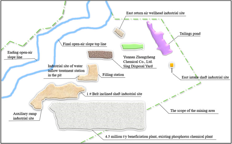
FIGURE 2. Site selection diagram of the filling station.
2.3 Geological conditions of the filling test area
The test area is positioned in the center of Kunyang Phosphate Mine No. 2. The filling test area is shown in Figure 3. The mining area is generally a tilted structure that slopes from south to east, and due to the gentle production of the ore layer, the open-air shape is relatively complicated. The distribution is from the south to the north of the mountains. The sedimentary-type phosphorus rock bed was formed, resulting in the production status of the mine layer being relatively stable, remaining consistent with the upper layer. Typically, the mine’s production status moves towards the northeast to the southwest and inclines at an angle ranging from 2° to 31°, tending towards the southeast.
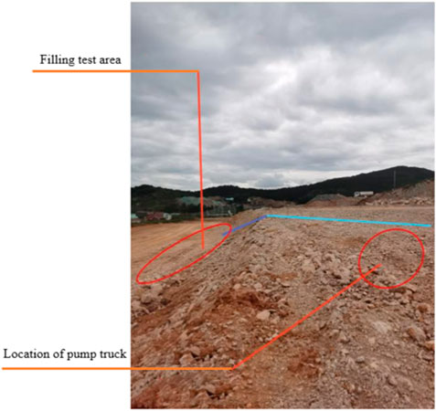
FIGURE 3. Filling the experimental area.
The upper layer of ore is distributed between exploration lines 58∼74, with an average thickness of 6.88 m and an average P2O5 content of 21.8%. The minimum thickness of the upper ore layer is 2.62 m, while the maximum thickness is 12.69 m. On average, the thickness measures 6.7 m, and the variation coefficient for thickness is 33%, indicating this layer is stable. Regarding its P2O5 content, the average grade is 22%, and the grade change coefficient is 17%, indicating that it is uniform. This layer contains I∼III grade ores, distributed in a spatial pattern that gradually becomes richer from the upper poor to the middle lower. The ore layer is relatively continuous and stable along the strike and dip. The interlayer mainly occurs in the southwest of the mining area (between exploration lines 63–74), while it is scattered in the east. The lithology consists of gray, white, and yellow clay, with a thickness ranging from 0 to 3.08 m. The rock thickness varies between 0 and 3.15m, with an average thickness of 1.08 m. The lower ore layer is distributed between exploration lines 58–74. The average thickness of the ore layer is 5.65 m, and the average content of P2O5 is 27.66%. The minimum thickness of the lower ore layer is 0.34 m, the maximum thickness is 12.77 m, the average thickness is 5.67 m, and the thickness variation coefficient is 36%, belonging to the stable type. The average content of P2O5 is 26.9%, and the grade change coefficient is 15%, belonging to the uniform type. I∼III grade ores are distributed in this layer and have a spatial distribution pattern of upper rich and bottom poor.
Based on the classification of ore products, the first-grade products (P2O5 content ≥25%) are located on the phosphorus ore’s intermediate and upper mine layers. Second-grade products (P2O5 content between 15% and 25%) are mainly located in the upper mine layer with phosphorus-containing layers. Third-grade products (P2O5 content between 8% and 15%) are situated in the middle and lower portions of the phosphorus ore layer.
The phosphate rock deposit in the experimental area is continuously deposited between rich and poor ore layers, with gradual changes in material composition and gradual transition in ore grade. The ore layer in the experimental section has good stability with continuous and stable strike and dip, with an average dip angle of 15°, making it highly suitable for filling in the experimental area.
3 Implementation plan for underground mining engineering
3.1 Overall plan and mining scale
This experiment is an industrial test project focused on underground mining and mining methods. Its primary objective is to seek effective mining methods suitable for underground mining, optimize the mineral structure parameters of the mining method, analyze and determine the safety hazard factors associated with underground mining, and conduct mining testing calculations—Economic Indicators. The mining method test will use the field’s production capacity as the assessment indicator. The mining production capacity is 2 million tonnes annually, with a filling capacity of 2.67 t/m³. As the mine scale is related to mining scope, methods, and equipment level (Bai et al., 2023), this trial will primarily evaluate the field’s production capacity, transportation capacity, and economic indicators during the test period.
3.2 Optimization of mining methods
Green mining is an inevitable trend in mining development (Deng et al., 2023; Hao et al., 2023; Yan, 2023). The filling mining method can greatly improve the mining recovery rate while the dilution rate is minimal. Additionally, this method provides the ability to mine the ore body under the principles of “Three underminings.” The filling mining method provides a high resource utilization rate and allows for effective control over ground pressure. Furthermore, this method significantly reduces water inflow into the mine and helps prevent geological disasters such as ground collapse, cracking, and mountain collapse. The filling mining method can fill the empty areas with waste rock and tailings. This eliminates the need for large waste rock dams and tailings ponds on the ground, which can significantly improve the surrounding environment of the mining areas and prevent potential conflicts between enterprises and local communities (Zeng et al., 2022a; Liu, 2022; Shen and Ning, 2022).
In this experiment, if the upward horizontal layered drift filling method is utilized by arranging ore rooms along the strike (Ren Q., 2021; Cui and Qi, 2023; Wu and Wang, 2023), it has good safety; Additionally, a larger number of ore rooms can be arranged in each panel, thereby improving production capacity. Nonetheless, the design does not deem this method suitable due to the complex process and poor ventilation environment. The upward horizontal layered filling method (with a vertically oriented layout of the ore house) can protect the roof via anchor bolts and reserve ore pillars and adjust to layered drift filling mining based on the ore body and surrounding rock conditions. When the panel slope is arranged outside of the vein, it exhibits good adaptability to the technical mining conditions of the ore body. However, it has a low recovery rate after reserving ore pillars and presents multiple constraints on the panel production capacity (Wang, 2023). The pseudo-inclined segmented strip-filling method (Zhang, 2014; Wang et al., 2022; Zeng, 2023) has the advantages of large panel production capacity, long service life, good safety, and good economy (Ren Y. D., 2021). The comparison of this experimental mining method is shown in Table 1.
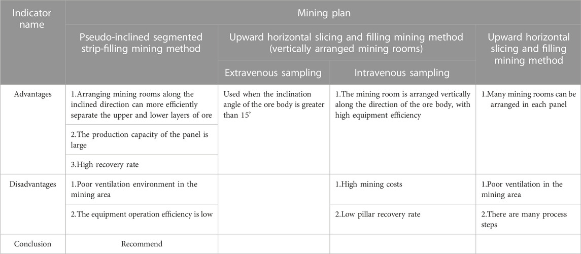
TABLE 1. Advantages and disadvantages of mining plans.
After analyzing and studying 88 boreholes within the designated mining area, the following conclusions can be drawn: Approximately 33.70% of individual projects have an upper ore bed thickness of ≤ 6 m, with an average thickness of 4.29 m. On the other hand, thicknesses greater than 6 m account for 66.30%, with an average thickness of 7.92 m. Additionally, individual projects with a thickness of ≤ 6 m in the lower seam represent 59.55%, with an average thickness of 4.39 m, while 40.45% are thicker than 6 m, with an average thickness of 7.56 m. A calculated approach has been implemented to enhance the recovery rate of the lower seam, mitigate inclusions, and maintain stable roof conditions in the upper seam. The pseudo-inclined segmented strip-filling mining method (I) is applied primarily to ore bodies with a thickness of ≤ 6 m, comprising 40% of the total, while the pseudo-inclined segmented strip-filling mining method (II) is utilized mostly for ore bodies with a thickness of>6 m, accounting for 50%. The remaining 10% of the mine is reserved for the upward horizontal layered filling method (Peng, 2022).
3.3 Filling system design
The process flow of the filling station is to transport the tail mortar produced by the flotation plant to the thickener of the filling station (Wang, 2020; Zeng et al., 2022b; Xu, 2022) and then pump the thickener to the mixer of the filling station through a slurry pump. The internally purchased crushed stones are stored in the crushed stone pile shed. Materials are loaded into the feed bin using a scraper and transported to the mixer via the belt when filling. Cementitious material is delivered to the filling station by a cement tanker and discharged through a soot-blowing pipe into the cement silo. The screw feeder at the bottom of the silo feeds the mixture to the mixer according to the required filling strength. They enter the filling pump after fully mixing the tail mortar, crushed stone, and cementitious materials. They are transported along the surface through the filling pipeline to the borehole near the east return air shaft before reaching the goaf for filling. The filling test equipment and filling station process flow are shown in Figure 4, 5. The station has three sets of filling pumps, two for normal operation and one for standby. Accident waste slurry and production wastewater are collected in the sewage collection tank, while clarified water is discharged to the high-level water tank. The accumulated waste sand is regularly cleared out. Apart from receiving overflow water, the sand return tank can also discharge the tailings deposited in the thickener to the sand return tank in case of a system failure.
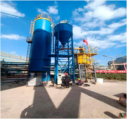
FIGURE 4. Filling test equipment.
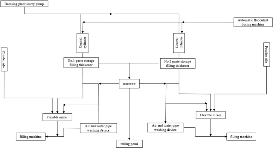
FIGURE 5. Filling station process flow.
The designed mining production scale is 2 million t/a, with 330 working days per year. The specific gravity of ore is 2.67 t/m³, and the filling system is also based on 330 working days per year. We need to meet the current production demand and consider that there should be a certain margin in filling system production capacity.
(1) Annual volume of empty space to be filled
In the formula:
(2) The annual consumption of full tailings cemented filling slurry volume is:
In the formula:
(3) Average daily filling volume required
In the formula:
(4) Maximum daily filling volume
In the formula:
(5) Hourly slurry preparation capacity of filling station
In the formula:
Design 2 sets of filling slurry with a separate preparation capacity of 100 m³/The filling system of H, with two sets of systems operating in parallel (two shifts) or a separate filling system operating continuously for 24 h, can meet production needs. The filling capacity calculation is shown in Table 2.
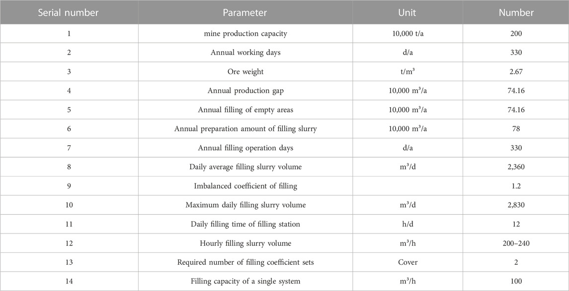
TABLE 2. Calculated values of filling capacity.
We calculated that the maximum daily filling slurry volume in the experimental area was 2,830 m³/d, and the average daily filling slurry volume was 2,360 m³/d. The filling system has two sets of filling pumping systems, comprising filling pumps, feeding belts, tailings feed pumps, paddle mixers, screw mixers, cement slurry, filling pumps, off-site gravel storage yards, and tailings deep cone thickeners.
The filling station has an aggregate storage yard and cement warehouse to meet the daily filling material volume. For this experiment, tailings and crushed stones serve as the main filling aggregates, and bulk cement is stored in a 300 t cement silo, which can provide materials for filling buffer for approximately 3 days. The gravel filling dosage is between 70–80 tons/hour, and each shift dose ranges from 420 to 480 t. One shift per day is worked, calculated based on an eighth shift. The gravel pile shed stores 3 days’ worth of filling materials, and the lattice screen on top of the feeding bin controls the size of the aggregate entering it. Three ZL50 loaders are configured for filling and loading. The filling system is equipped with two cement silos, and the storage capacity of each silo should be no less than the demand for 3 days. The maximum daily consumption of cement is 400 t, so the storage capacity of each cement silo should be no less than 300 t, with an effective volume of 250 m³, which can meet the cement consumption needs for 3 days. A transmission pipeline has been constructed from the concentrator to the tailings pond, with a branch pipe connected starting from pipeline stake No. PN11 leading to the filling station. The pipeline is utilized for filling purposes after concentration.
The horizontal mixing system used in this design boasts several advantages, such as low equipment and small building height requirements, mature equipment with high performance, and convenient installation and maintenance. For each system, we recommend using two stages of mixing: double shaft blade mixer and double screw mixer, with a mixing capacity of 100–120 m³. During mixing, the tail mortar is first diluted in a central barrel and then mixed evenly with the flocculant. It is then concentrated and settled before being metered and batched by the weighing system. Crushed stone is transported to the main material hopper by a belt conveyor, while bulk cement is stored in a weighing hopper through a cement weighing system. The water used for filling the slurry comes from the production water of the concentrator. A proper proportion of full-tail mortar, cement, and concentrated water is measured and added to the mixer to mix evenly. The filling material should be thoroughly stirred to create a slurry with a moderate concentration and excellent fluidity, ensuring that it can be easily supplied to the filling material delivery pump or the lower hopper of the filling borehole.
A concrete pump then transports the mixed filler slurry. Before feeding the concrete delivery pump, it is important to ensure even mixing of the concrete. During feeding, unloading should be carried out uniformly in conjunction with pumping while maintaining the concrete above the height mark line in the aggregate hopper. A mesh screen should also be placed on the concrete pump feed hopper, and someone should be assigned to monitor the feeding process carefully to prevent excessive particle size aggregate or foreign matter from entering the pump and causing a blockage.
In order to make the filling slurry transportation system adopt self flow transportation, it is necessary to calculate the pipe diameter and theoretical thickness of the self flow transportation system separately.
(1) Calculation of the pipe diameter of the self flow transportation system:
Many filling mines at home and abroad use seamless smooth pipes and pipeline steel as filling pipelines. This time, pipeline steel is used as filling pipelines. According to the flow rate of the filling slurry in the semi industrial test section, which is 1.4–18 m/s, the minimum inner diameter of the filling pipeline is:
In the formula:
(2) Theoretical thickness calculation of pipeline:
In the formula:
K is the amount of wear and corrosion, taken as 4 mm.
After calculation,
To improve the wear resistance of the filling pipeline, the main pipe adopts 16 Mn seamless steel pipes with strong wear resistance. Based on the above calculation results, the specifications of the main pipe are Φ 168 mm × 14 mm, actual effective inner diameter of pipeline DI=140 mm; Branch pipe, 8-4 MPa, steel pipe specification Φ 168 mm × 10 mm, effective inner diameter DI=148 mm; 4-0MPa, steel pipe specification Φ 168 mm × 8 mm, effective inner diameter DI=152 mm, and DN150 ultra-high molecular weight polyethylene pipes are used in the end segmented branch line and mining area.
When filling industrial pumps, it is essential to consider pipe plugging and outlet pressure fully. The pipes should be arranged in an S-shaped fashion to achieve optimal results. The flow rate for these industrial pumps should be set between 100 and 120 m³/h. When the distance is relatively close, the high-volume filling can be utilized.
The selection of the location of the filling station and the filling pipe in the well is complementary, and the combination of the two directly determines the filling of multiple lines of the pipeline. The filling pipe needs to be transported 400 m across the ground to reach the borehole for filling. Considering both surface topography and subsurface development, the east vertical air shaft was filled by drilling in the early stage, providing service to the mined-out areas above 1,890 m in the east. In the later stage, it fills the east and west mined-out areas below 1890m through the central air intake shaft.
Through research on mining technology and theoretical numerical calculation of the filling test section of Kunyang Phosphate Mine No. 2, preliminary Table 3 shows the power equipment of the filling system:
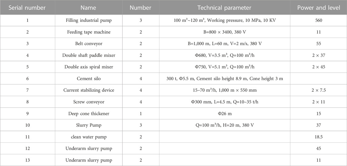
TABLE 3. Main power equipment of the filling system.
According to the above filling experimental calculation requirements, the main power equipment for the filling system is selected as shown in Table 3.
4 Problems that still exist during the filling process
Slightly inclined thin to medium-thick ore bodies have typical characteristics, such as slow dip angles, large changes in ore body shape, and unclear ore-rock boundaries. These features pose technical difficulties for both open-pit and underground mining, resulting in high loss rates, high dilution rates, and low resource recovery rates. These difficulties seriously restrict the development of phosphorus ore mining technology in China. Currently, the main problems in mining gently inclined thin to medium-thick phosphorus ore bodies persist, including.
(1) The mechanical equipment, mining methods, and technology necessary for underground mining of these ore bodies have not been resolved yet.
(2) The stability of the filling system operation and the overall filling process is relatively complex. The stability of each subsystem is particularly critical to the overall system, and any problem in the filling process can lead to the stoppage of filling work.
(3) There are few studies on the underground mining of gently inclined thin to medium-thick phosphorous ore bodies, especially for fractured and unstable ones.
(4) The research on the preparation and process of filling slurry is still imperfect. The filling effect’s core issue lies in the filling slurry’s preparation effect. If the filling effect is not good, it can lead to problems such as side chipping or large area collapse, increasing safety risks.
(5) There are no significant breakthrough research results on the rock movement and surface subsidence caused by underground mining of phosphate mines, and the relevant theoretical system is far from mature and perfect. It is still in the preliminary research stage.
5 Conclusion
The gently inclined thin to medium thick ore body refers to an ore body with an inclination of 5°–30° and a 1.0–15 m thickness. The Kunyang Phosphate Mine No. 2 has an average inclination angle of 15°, typically a gently inclined thin to medium-thick deposit. Through research on phosphate mining and filling technology, the following conclusions are drawn.
(1) Gently inclined thin to medium-thick phosphate ore deposits are mainly mined using the pseudo-inclined segmented strip drift filling method arranged along the ore room, supplemented by the upward horizontal layered drift filling method. This approach can increase the production capacity of coiled coils, improve the recovery rate, and separate the mining of upper and lower layers of ore, ultimately increasing the mining efficiency of phosphorus mines and extending the service life of the mine.
(2) The selection of the filling station site for Kunyang Phosphate Mine No. 2 not only follows basic standards, but also meets the current filling requirements for the eastern part and the filling requirements for the western ore body. The filling slurry prepared by the filling station can be directly transported to various mining sites through the filling boreholes in the station, and then flows to various underground mining sites through the filling boreholes, achieving the “self flow” transportation of the filling slurry.
(3) Based on the designed production scale of 2 million tons/a, the annual volume of the filling area required for the filling station, the annual consumption of all tailings cemented filling slurry volume, the daily average filling volume, the daily maximum filling volume, the hourly preparation capacity of the filling station slurry, as well as the calculation of the diameter of the gravity conveying pipeline and the theoretical thickness of the pipeline, were calculated through theoretical values. This provides technical and theoretical support and equipment selection for mine filling experiments. This paper focuses on Kunyang Phosphate Mine No. 2, under Yunnan Phosphate Chemical Group, and studies the filling mining technology after underground mining. The relevant research results are significant in guiding the underground mining and construction of difficult-to-mine phosphorous ore bodies in the Yunnan Dianchi region.
Data availability statement
The original contributions presented in the study are included in the article/Supplementary Material, further inquiries can be directed to the corresponding authors.
Author contributions
DH: Conceptualization, Writing–original draft. MX: Validation, Writing–original draft, Writing–review and editing. XL: Investigation, Validation, Writing–review and editing. JW: Visualization, Validation, Writing–original draft. MW: Writing–original draft, Validation. SL: Validation, Writing–original draft.
Funding
The research work was funded by the Research Fund of National Natural Science Foundation of China (NSFC) (Grant No.42277154), the project of Slope safety control and disaster prevention technology innovation team of “Youth Innovation Talent Introduction and Education Plan” of Shandong Colleges and universities (Grant No. Lu Jiao Ke Han [2021] No. 51); Guizhou Province Science and Technology Planning Project (Grant No. Guizhou science and technology cooperation support [2022] common 229), National Natural Science Foundation of Shandong Province of China (NSFC) (Grant No. ZR2022ME188), Jinan City “new university 20” research leader studio project (Grant No. 20228108), The State Key Laboratory of Coal Resources and safe Mining, CUMT (SKLCRSM22KF009), and Open Fund of National Engineering and Technology Research Center for Development and Utilization of Phosphate Resources of China (Grant No. funded the research work NECP 2022-04) and the Open Fund of Key Laboratory of Geological Hazards on Three Gorges Reservoir Area (China Three Gorges University), Ministry of Education (Grant No. 2022KDZ07).
Conflict of interest
Authors MX, MW, and SL were employed by Yunnan Phosphating Group Co., LTD.
The remaining authors declare that the research was conducted in the absence of any commercial or financial relationships that could be construed as a potential conflict of interest.
Publisher’s note
All claims expressed in this article are solely those of the authors and do not necessarily represent those of their affiliated organizations, or those of the publisher, the editors and the reviewers. Any product that may be evaluated in this article, or claim that may be made by its manufacturer, is not guaranteed or endorsed by the publisher.
References
Bai, Y., Zhou, Y. B., and Cui, Y. (2023). Etc Research on the upward horizontal slicing and filling mining method for steep inclined thin ore bodies outside the vein. Min. Res. Dev. 43 (05), 1–6. doi:10.13827/j.cnki.kyyk
Bin, T. (2016). Application of pseudo-inclined arrangement in gently inclined thin ore body in mining method. Eng. Constr. 48 (03), 33–36+78. doi:10.13402/j.gcjs
Cui, Na., and Qi, J. J. (2023). Research trends and prospects of green mining in China. Resour. Inf. Eng. 38 (01), 60–64. doi:10.19534/j.cnki.zyxxygc
Deng, G. L., Zheng, B. K., and Li, X. D. (2023). Research on filling mining technology in qianhe gold mine. Min. Technol. 23 (04), 196–198. doi:10.13828/j.cnki.ckjs
Erdenv, (2022). Mining technology and safety of open-pit mining. Inn. Mong. Coal Econ. 357 (16), 115–117. doi:10.13487/j.cnki.imce
Gong, X. L. (2022). Main problems and countermeasures of deep mining in underground mining. China Met. Bull. 1064 (03), 16–18.
Hao, Y. J., Wang, C. L., Jiang, M. W., et al. (2023). Optimization of upward drift filling mining method and ground pressure control for gently inclined medium thick ore bodies. Non Ferr. Met. Eng. 13 (05), 114–121.
Huang, J., Li, S. J., Xia, G. Y., Wang, M. L., Zhang, B., and Liu, Y. H. (2022). Study underground mining method of gently inclined medium and thick ore body of Kunyang phosphate ore No. 2 ore. Mod. Min. 38 (07), 45–50+55.
Jiang, A. M., Dong, Y. C., Jiang, X. L., Xiong, Q. W., and Wang, F. F. (2022). Numerical simulation study on slope collapse caused by open-pit to underground mining. Min. Metallurgical Eng. 42 (03), 14–17.
Jin, J. R., Zhang, F. G., Tang, M. W., Yang, Z. B., Zheng, Z., Tang, T., et al. (2017). Experimental study and application of mechanized pseudo-tilted slitting mining method for disk area. Gold 38 (07), 33–39.
Lao, Y. X., Deng, G. L., Zheng, B. K., and Zhang, L. Y. (2022). Application of upward layered full tailings cementation filling mining method in cold-water copper nickel ore. Min. Technol. 22 (06), 161–162+165. doi:10.13828/j.cnki.ckjs
Li, G. Z. (2022). Progress and the prospect of exploration of underground mining technology in metal mines. World Nonferrous Met. 609 (21), 169–171. doi:10.19614/j.cnki.jsks
Li, Q. H., Song, D. Q., Yuan, C. M., and Nie, W. (2022). An image recognition method for the deformation area of open-pit rock slopes under variable rainfall. Measurement 188, 110544. doi:10.1016/j.measurement.2021.110544
Li, X. S., Li, Q. H., Wang, Y. M., Liu, W., Hou, D., Zheng, W. B., et al. (2023). Experimental study on instability mechanism and critical intensity of rainfall of high-steep rock slopes under unsaturated conditions. Int. J. Min. Sci. Technol. doi:10.1016/j.ijmst.2023.07.009
Li, X., Wang, Y. M., Zhao, K., and Yang, S. (2019). Research progress on key issues of open-pit to underground mining of metal mines. Metal. Mine (12), 12–20. doi:10.2478/AMNS
Li, X. S., Wang, Y. M., Yang, S., Xiong, J., and Zhao, K. (2021). Research progress in the mining technology of the slowly inclined, thin to medium-thick phosphate rock transition from open-pit to underground mine. Appl. Math. Nonlinear Sci. 6 (1), 319–334. doi:10.2478/amns.2021.2.00017
Liu, Y. H. (2022). Prediction of water inflow in underground mining pit of Kunyang phosphate ore No. 2 mine. Chem. Mineral Geol. 44 (01), 78–85.
Peng, J. (2022). Multi-objective optimization of stope structural parameters by upward horizontal layered filling method. Mod. Min. 38 (08), 68–72.
Qu, L. P., and Wang, Y. Q. (2021). The application of upward horizontal slicing and filling mining method in steeply inclined and fractured thin ore bodies. Min. Res. Dev. 41 (12), 1–4. doi:10.13827/j.cnki.kyyk
Ren, Q. (2021a). Application and related problems of fill-fill mining technology in mining. Inn. Mong. Coal Econ. 327 (10), 10–12.
Ren, Y. D. (2021b). Application of upward horizontal layered step-and-step fill mining method in Honghuagou gold mine. Gold 42 (10), 49–53+58.
Shen, D. Y., and Ning, G. J. (2022). Hydrogeological characteristics of Kunyang phosphate ore No. 2 ore and water prevention and control of inclined shaft engineering. China Min. Eng. 51 (01), 86–89. doi:10.19607/j.cnki.cn11-5068/tf
Wang, B. (2023). Analysis of the status quo and countermeasures of mine ecological restoration. Surf. Min. Technol. 38 (01), 125–128. doi:10.13235/j.cnki.ltcm
Wang, X. (2020). Application of upward horizontal layered approach filling method in Xiajiadian gold mine. Mod. Min. 36 (06), 83–86.
Wang, X. R., Zhao, B. S., Liang, J. L., and Gong, Y. C. (2022). Study the optimization of mining method by refilling and filling a copper mine. Min. Technol. 22 (06), 158–160. doi:10.13828/j.cnki.ckjs
Wei, G. D., Zhen, D. S., and Liu, Z. Y. (2022). Discussion on mining technology and safety of open-pit mining. Inn. Mong. Coal Econ. 345 (04), 97–99. doi:10.13487/j.cnki.imce
Wu, H. J., and Wang, L. (2023). Analysis of key points of green mine construction. Min. Technol. 23 (01), 202–204. doi:10.13828/j.cnki.ckjs
Xu, A. H. (2022). Analysis and study of upward horizontal approach filling method. World Nonferrous Met. 612 (24), 190–192.
Yan, H. F. (2023). Discussion on the application of strip paste filling mining technology in mining engineering. Contemp. Chem. Res. (14), 92–94. doi:10.20087/j.cnki.1672-8114
Zeng, J. L., Zhou, Y., and Gao, X. (2022a). Etc Stability analysis of the stope using pseudo inclined segmented strip filling mining method. Min. Technol. 22 (04), 107–111. doi:10.13828/j.cnki.ckjs
Zeng, J. L., Zhou, Y., Gao, X., He, B. L., Guo, H. Q., Liu, Q., et al. (2022b). Stability analysis of stope by pseudo-inclined segmented strip filling mining method. Min. Technol. 22 (04), 107–111. doi:10.13828/j.cnki.ckjs
Zeng, L. Y. (2023). Optimization of low-grade inclined medium-thick ore body filling mining method. Gold 44 (02), 22–26.
Zhang, R. D., Li, J., and Zhu, C. D. (2021). Panel staggered upward horizontal slicing and filling mining method. Min. Technol. 21 (02), 18–21. doi:10.13828/j.cnki.ckjs
Zhang, R. X., Wang, Q. Y., Wang, M. L., Wang, H. L., and Huang, J. (2022). Experimental study on cementation filling of phosphate ore flotation ultrafine whole tailings. Min. Res. Dev. 42 (09), 39–43. doi:10.13827/j.cnki.kyyk
Zhang, Y. J. (2014). Application and development of fill-and-fill mining method in mining process. Heilongjiang Sci. Technol. Inf. (19), 4.
Zhu, F., Liu, X. S., and Zhang, M. (2020). Experimental study on cementation filling of tailings in a lead-zinc mine in Gansu Province. China Min. J. 29 (S1), 502–505.
Keywords: gently inclined phosphate rock, filling technique, underground-mining, filling system, technical guidance
Citation: Hou D, Xu M, Li X, Wang J, Wang M and Li S (2023) Study on filling mining technology for gently inclined thin to medium thick phosphorus deposits. Front. Earth Sci. 11:1254509. doi: 10.3389/feart.2023.1254509
Received: 07 July 2023; Accepted: 22 September 2023;
Published: 09 October 2023.
Edited by:
Qihua Ran, Hohai University, ChinaReviewed by:
Min Xiong, Tongji University, ChinaJixiong Zhang, China University of Mining and Technology, China
Linqi Huang, Central South University, China
Copyright © 2023 Hou, Xu, Li, Wang, Wang and Li. This is an open-access article distributed under the terms of the Creative Commons Attribution License (CC BY). The use, distribution or reproduction in other forums is permitted, provided the original author(s) and the copyright owner(s) are credited and that the original publication in this journal is cited, in accordance with accepted academic practice. No use, distribution or reproduction is permitted which does not comply with these terms.
*Correspondence: Mengchao Xu, Mjc1MDY5MDQzN0BxcS5jb20=; Jiawen Wang, MjYwMTQzNzc0MEBxcS5jb20=