 Zelin Zhou1
 Rong Liu
- 1China 19th Metallurgical Corporation, Chengdu, China
- 2State Key Laboratory of Coal Mine Disaster Dynamics and Control, Chongqing University, Chongqing, China
- 3School of Resources and Safety Engineering, Chongqing University, Chongqing, China
- 4Chongqing City Construction Investment (Group) Co., Ltd., Chongqing, China
- 5Zhonghuan Construction Co., Ltd., Chongqing, China
- 6Zhalainuoer Coal Industry Co., Ltd., China Huaneng Group Co., Ltd., Hunlunbuir, China
As the length of the tunnel continues to increase, it will be common for a single fan to undertake the ventilation of two or more tunnel faces. However, the construction of multiple faces in a single tunnel will lead to a complex construction environment in the tunnel, the mutual interference of ventilation, and difficulty in discharging pollutants. Based on the simultaneous construction of multiple tunnel faces in a single tunnel, this study analyzed the transport law of pollutants. The diffusion laws of carbon monoxide and dust in multiple-face tunnels under different working conditions were obtained by numerical simulation. It was found that when both sides of the tunnel are ventilated at the same time, the airflow in the tunnel is spiral, the vortex zone will appear near both sides of the face, and the vortex and unstable airflow will appear at the intersection with the inclined shaft. The airflow in the non-equal-length tunnel at both sides is more disordered than that in the equal-length tunnel, and there will be a wider range of eddy currents at the intersection. The change of dust diffusion in the non-equal-length tunnel at both sides is not obvious, and the length of the multiple-face tunnel has little effect on dust settlement and diffusion. The research results are of great significance for improving the construction environment of tunnel faces and improving the working conditions of personnel.
1 Introduction
The tunnel plays an important role in the highway, which can shorten the driving distance, improve transportation capacity, and reduce accidents (Ma et al., 2021; Fang et al., 2022; Liu et al., 2023). With the continuous development of tunnel construction, the tunnel length has become increasingly longer (Liu et al., 2020). In order to shorten the construction period, inclined shafts are often used to increase the construction face, which will increase the number of working faces (Zhao et al., 2023). However, each face needs enough fresh air during the working period, which leads to higher requirements for the ventilation system. Due to the area of the inclined shafts, the situation in which a fan provides air to two or three tunnel faces at the same time will become more common. In the case of no restrictions, the airflow will flow to the side with less resistance, resulting in very little air volume on the other side. Therefore, when a fan supplies air to multiple faces, it is necessary to artificially interfere with the airflow to make it reach the required face.
In the process of tunnel construction, blasting, excavation, and transportation of slag, shotcrete, a lot of harmful gases, and dust will be produced (Rodriguez and Lombardia, 2010; Liu et al., 2012; Rodriguez et al., 2012; Shao et al., 2016). In some specific geological conditions, combustible gases may be produced. In a tunnel constructed by the drilling and blasting method, a lot of poisonous and harmful gases will be released after the explosion (Fang et al., 2016). In addition, the exhaust gas produced by the internal combustion engine of the mechanical equipment and the working vehicle will also be discharged into the tunnel (Lang et al., 2016; Lin et al., 2017; He and Jiang, 2018; Li et al., 2018). Because the tunnel is semi-closed during construction, it is difficult to remove pollutants from it. When one fan supplies air to multiple faces, the pollutants from multiple faces will also gather and discharge from the same auxiliary construction tunnel, further increasing the difficulty of ventilation and sewage.
In order to guarantee the physical and mental health of tunnel construction workers and to ensure the smooth development of tunnel construction, scholars have carried out plenty of research. Hargreaves DM et al. simulated an airflow field in a roadway to provide theoretical guidance for design (Hargreaves and Lowndes, 2007). Haas A and RAO Am built a three-dimensional mathematical model of a tunneling construction tunnel and studied the wind flow characteristics near the face by using the CFD method, providing a basis for tunnel construction design (Haas et al., 2002; Rao et al., 2015).
For the problem of a single fan with multiple faces, many scholars have focused on the ventilation mode of the air-box. Many scholars have carried out optimization research on the length, width, and partition length of the air-box. Tao et al. used field tests and three-dimensional numerical models to study the effects of box length, partition length, and fan arrangement on ventilation efficiency (Tao et al., 2022). Cao (2016) obtained the calculation formulas of the influence coefficient of the length, width, and height of an air-box through numerical simulation, concluding that the air-box increased the air volume by 19.9%. Luo Gang obtained the optimal length and height of an ordinary air-box (Luo et al., 2020). Luo Yanping adopted a three-dimensional numerical model and concluded that the air-box can better control the air volume at the outlet of the air duct of the working face and reduce the length and angle of the air duct, thus reducing air leakage and wind pressure loss (Luo et al., 2019). Song Junxiu adopted the control variable method and determined the optimal air-box size based on the efficiency of the fan, the total wind pressure, and the smoothness of the airflow (Song et al., 2020). Yang Shanshi concluded that the ventilation efficiency of the fan connection type is the best, the blowdown capacity in the tunnel is good, followed by the airbox connection type, and the press-in type is the worst (Shan-shi et al., 2022). Zhou Shuiqiang analyzed the CO concentration distribution in tunnels under the two modes of press-in ventilation and air-box ventilation by numerical simulation, concluding that the air-box can greatly extend ventilation distance, improve ventilation efficiency, and effectively improve CO concentration distribution in tunnels, which is of great significance for multiple-face ventilation in long tunnels (Zhou, 2018). The influence of factors such as the spacing position of the air-box, the length of the air-box, and the relative position between the air-box and the air duct in relation to the air volume and pressure is also studied. Through comparison and analysis, the most reasonable air duct layout can be obtained so as to effectively improve the CO concentration distribution in the tunnel. Taking Jingguashan Tunnel as the research background, Li Yong considered three different ventilation modes to provide a reference for the long tunnel with multiple-face air supply (Li et al., 2013). Based on the research background of the West Qinling Tunnel, Dou Xiaotian explored the ventilation scheme under the condition of two hand ways of air supply in the inclined shaft and focused on the relay ventilation method of the air chamber, which economically and efficiently improved the working environment in the construction tunnel (Dou and Chen, 2011). Chen Haifeng took Changhongling Tunnel as the research object and conducted a detailed study on the variation rule of the flow field in the air-box used in the tunnel, the reasonable disposition position of the fans, and its influence on the flow in the box (Chen, 2022). Xin Guoping also took Changhongling Tunnel as an example, focusing on the ventilation scheme of the combined ventilation of the divided roadway and air duct, studying several key parameters, and designing three dynamic schemes with good ventilation effect (Guoping, 2015). Liu Guoping proposed a new ventilation scheme of small air-box relay ventilation, aiming at the ventilation scheme under the condition that the air supply of the inclined shaft is driven into two faces in both directions and the tunnel section is small, making the ventilation distance reach 6,386 m at its longest (Liu, 2013). Li Xiuchun put forward the ventilation method of “shaft + air box + air duct” based on the research background of complex underground air storage tunnels and explored the airflow characteristics and ventilation efficiency of the air bin under different parameter sizes and the optimal fan placement situation (Li et al., 2015).
The aim of this study is to master the migration and distribution of pollutants when facing multiple faces during tunnel construction, to master the laws of ventilation and drainage in the construction of tunnels with multiple faces, and to provide solid theoretical support for the ventilation methods and technologies employed in the construction of these tunnels. The numerical simulation method is used to analyze and study the characteristics of airflow field and pollutant migration and discharge in tunnels during construction and to explore the characteristics of airflow and the law of pollutant diffusion and migration under different construction conditions.
2 Governing equation of tunnel airflow
The airflow in the tunnel follows the basic conservation laws of mass conservation, momentum conservation, and energy conservation. The following are the basic equations of motion for three-dimensional unsteady viscous fluids:
(1) Mass conservation equation: According to the law of conservation of mass, in fluid mechanics, the net mass per unit time flowing into the fluid cell is equal to the increase in mass in the fluid cell, and the equation is as follows:
where ρ is density, kg/m3; t is time, s; and u, v, and w are the components of the velocity vector u in the x, y, and z directions, respectively.
(2) Momentum conservation equation: According to the law of conservation of momentum, the sum of all external forces acting on the microelement is equal to the change rate of the momentum of the fluid in the microelement with respect to time, and the equation is as follows:
where fx, fy, and fz are the components of the volume force acting on a unit mass gas in the x, y, and z directions, respectively, N/kg; μ is aerodynamic viscosity coefficient, kg⋅s/m2.
(3) Energy conservation equation: The net heat flow into the cell plus the work done by the physical and surface forces on the cell is equal to the increase rate of energy in the cell; the equation is:
where e is internal energy per unit mass of gas, J/kg; k is coefficient of heat conduction, W/m⋅K;
During tunnel excavation blasting, a large amount of smoke will be formed in front of the tunnel face, which is called the smoke throwing area. In the case of ventilation, the diffuse smoke in the tunnel will gradually move along the direction of fresh air to the inclined shaft, which is a dynamic change process. The displacement process of blast smoke pollutants satisfies the law of conservation of mass, Fick’s first law, and Boshenick’s hypothesis. The diffusion equation during its migration can be expressed as:
where ϕ is particle CO mass concentration, mg/m3.
According to Boshenick’s hypothesis:
where
The instantaneous value of CO mass concentration in blast smoke is the sum of the average value of CO concentration and the fluctuation value of concentration. Because the smoke pulsation is usually random, its value is approximately zero, and the disturbance to the mass concentration of carbon monoxide is small, so it can be ignored in the actual calculation. Similarly, the instantaneous wind speed in the x, y, and z-axes can also be ignored because of the pulsation value. In summary, the following formula can be obtained:
This equation is the differential equation of CO migration in a single-head roadway.
The movement of dust in the tunnel belongs to a kind of gas–solid two-phase flow, and the mathematical models describing the gas–solid two-phase flow can be divided into two categories, namely, a continuum model and particle orbit model. For the convenience of the study, dust transport in the tunnel is regarded as a continuous medium.
In the tunnel, the main factors of dust diffusion are airflow convection, diffusion movement, and turbulent pulsation diffusion. The causes of dust deposition along the height direction are gravity deposition, diffusion deposition, turbulent diffusion, and deposition, among others.
3 Typical multiple-face tunnel construction
Due to the increasing length of tunnels, the proportion of multiple-face tunnel construction is increasing. Whether in the excavation of a highway tunnel or the construction of an underground tunnel group for a hydropower station, multiple-face tunnel construction will occur. The so-called multiple-face tunnel construction refers to the simultaneous construction of multiple faces in a single tunnel. Considering the problem of the section area of the inclined shaft, it is often impossible to provide a dedicated ventilation system for each face, and only the fresh air in one air duct can be transported to different faces by shunt. After cleaning each face, the air is finally collected and discharged in the auxiliary construction tunnel (inclined shaft or special ventilation tunnel). At present, tunnels forming multiple working faces can be divided into two cases: the auxiliary construction of a ventilation shaft leads to the increase of the working face, and the special auxiliary tunnel construction leads to the increase of the working face. The following three typical multi-face construction situations are introduced through actual construction cases.
Tianshan Shengli Tunnel is 22.035 km long and belongs to the extra-long tunnel. The tunneling distance is up to 11 km. Using TBM to excavate the middle drift, the advantage of the lead of the middle drift was used to enter the main tunnel through the transverse tunnel to open up the working face. In this way, the speed of tunnel penetration could be achieved. During the construction period, due to the space limitation of the middle drift, only four fans could be arranged. However, seven faces were constructed at the same time. The ventilation of the tunnel is shown in Figure 1A, where the 1# fan supplies air to three faces, and the 2# fan supplies air to two faces.
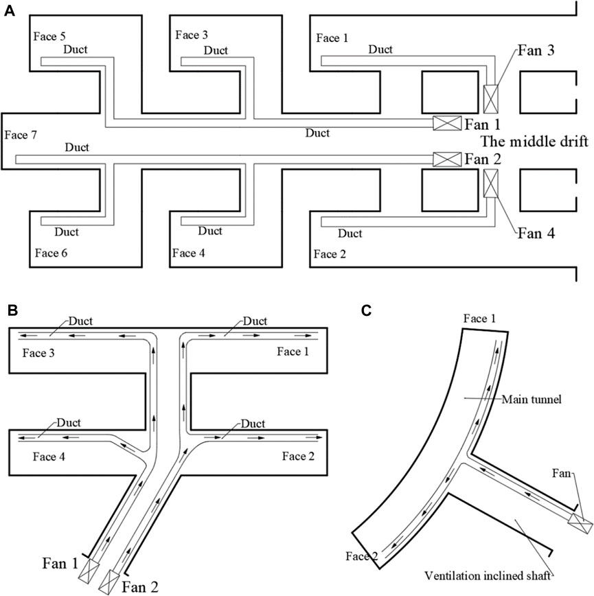
FIGURE 1. Ventilation organization diagram of typical multiple-face construction tunnel.
Wulaofeng extra-long tunnel is a double-line separated tunnel with the length of 8.340 km. Wulaofeng Tunnel has two ventilation inclined shafts. Ventilation incline can be used as an auxiliary passageway during construction. During the construction period, after the inclined shaft entered the main hole, there were four faces working at the same time in the shafts, and the ventilation mode is shown in Figure 1B. Due to the small section of the inclined shaft, only two fans could be arranged to provide fresh air for the four faces.
Xisujiao 2# Tunnel is 1823.5 m long. The tunnel structure is multi-arch–small clear distance–separate type–small clear distance–multi-arch. Because the entrance and exit of the Xisujiao 2# tunnel is steep, it is impossible to enter the main tunnel. Therefore, on the northwest side near the exit portal, a construction adit was excavated to enter the main tunnel. The length of the construction adit is 763.5 m. During the construction period, two fans were arranged at the portal of the construction adit to provide fresh air to the four faces of the main tunnel. The ventilation mode is shown in Figure 1C.
With the deepening of construction in the west of China, there will be more and more multiple-face construction situations, and the migration characteristics of pollutants in multiple-face construction tunnels also need further in-depth study. Through the actual investigation of the ventilation conditions of the above tunnels, it is found that the construction of multiple faces will not only occur in long tunnels but also in short tunnels. Once one fan provides fresh air to multiple faces at the same time, the environmental state of the tunnel will be very bad, and the connection mode of the duct will also affect the airflow, which will then affect the air supply of the face. Therefore, the characteristics of airflow and the transport characteristics of pollutants during the construction of multiple palm surfaces are required to be examined first.
4 Study on the law of pollutant diffusion in an equal-length tunnel at both sides
4.1 Geometric model and boundary condition setting
It is generally believed that if the two sides are equal in length, the airflow will be more uniform, so the situation of equal length at both sides must first be studied. In this case, if the ventilation effect is indeed very good, which can be achieved through the adjustment of the construction organization, the geometric model in this study is set as follows: the tunnel section has a radius of 5.9m, the excavation construction tunnel is divided into left and right parts, each side is 200 m long (equal length on both sides), and the ventilation inclined shaft perpendicular to the construction tunnel is 75 m long, which is especially excavated for the ventilation of the multiple-face tunnel construction. The ventilation modes of the two tunnel tunnels are compressed ventilation, and the tunnel of the two palm faces is used for air supply and pressure regulation. The air duct is arranged in the center of the inclined ventilation shaft at a height of 3.5 m from the tunnel ground and in the construction tunnel at a side arch at 3.5 m from the tunnel ground. SCDM software has been used to model the geometric model and the Meshing module in Ansys Workbench for meshing. The tunnel geometry model and mesh division are shown in Figure 2, and local encryption is carried out near the palm surface and the wind duct, which not only improves the calculation accuracy but also saves computing resources.
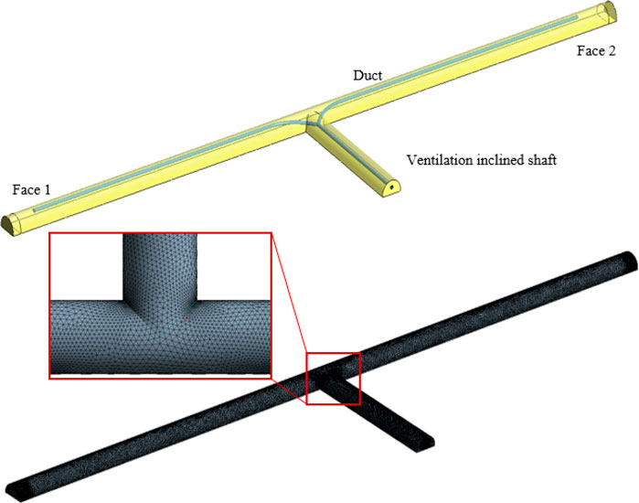
FIGURE 2. Tunnel geometry model and meshing.
The CO produced by simulated blasting and dust produced by shotcrete has been studied. The boundary conditions are set in Tables 1–3.

TABLE 1. Setting of boundary conditions for simulating carbon monoxide diffusion.
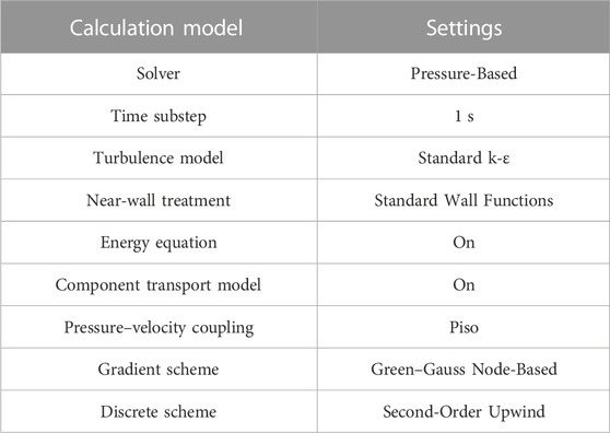
TABLE 2. Calculation model for simulating carbon monoxide diffusion.
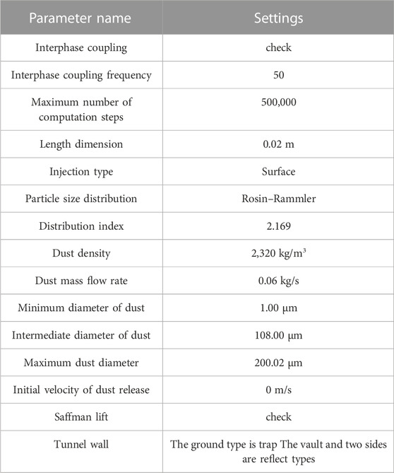
TABLE 3. Discrete phase model parameter settings.
4.2 Study on CO diffusion law in construction of equal-length tunnel at both sides
In tunnel construction, the blasting process is an instantaneous process. It is generally believed that CO is an instantaneous pollution source and will evenly fill the space near the tunnel face. In this study, blasting operations carried out at both sides of the face are considered. Figure 3 shows the CO diffusion law after blasting. It can be seen from the figure that the produced carbon monoxide gathers near the tunnel face after blasting for 10 s. With the continuous action of fresh airflow and the molecular diffusion of CO molecules from high concentration to low concentration, it gradually migrates to the tunnel exit. At 50 s, the CO migrates to half of the tunnel at both sides. When approaching 200 s, the carbon monoxide produced by both sides of the tunnel reaches the intersection of the tunnel and the inclined shaft and moves toward the portal of inclined shaft. It can be seen that the concentration of carbon monoxide near the tunnel face is always high before 200 s, and the distribution range of high-concentration carbon monoxide gradually expands. Meanwhile, carbon monoxide fills almost the entire tunnel, while the concentration near the tunnel face continues to decrease. After 300 s, part of the carbon monoxide is discharged out of the tunnel, and the concentration around the tunnel face further decreases with continuous ventilation. The carbon monoxide diffusion of both sides of the tunnel face is symmetrical in distribution, and carbon monoxide is basically discharged out of the hole at 800 s.
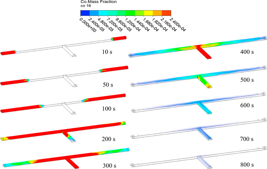
FIGURE 3. The distribution of CO mass fraction at different moments of the equal-length tunnel.
The CO distribution cloud images of tunnel sections with different distances from the tunnel face were captured, as shown in Figure 4. It was found that the distribution of CO in the tunnel is opposite at 20 m and 30 m away from the face. At 20 m, CO gathers at the side near duct, and it gathers at the side far of duct at 30 m. A large range of the eddy current region will be generated near the tunnel face, and the airflow is relatively unstable, so carbon monoxide forms a spiral movement in the eddy current. Therefore, the distribution of CO concentration varies greatly at different locations. At the same time, it can be clearly seen that the CO concentration in the tunnel section presents a distribution of high in the middle and low in the periphery. The closer the tunnel wall is, the lower the CO concentration is, which indicates that the resistance along the tunnel wall will have a greater impact on the diffusion and migration of CO, so carbon monoxide will accumulate in the space with low resistance in the middle of the tunnel.
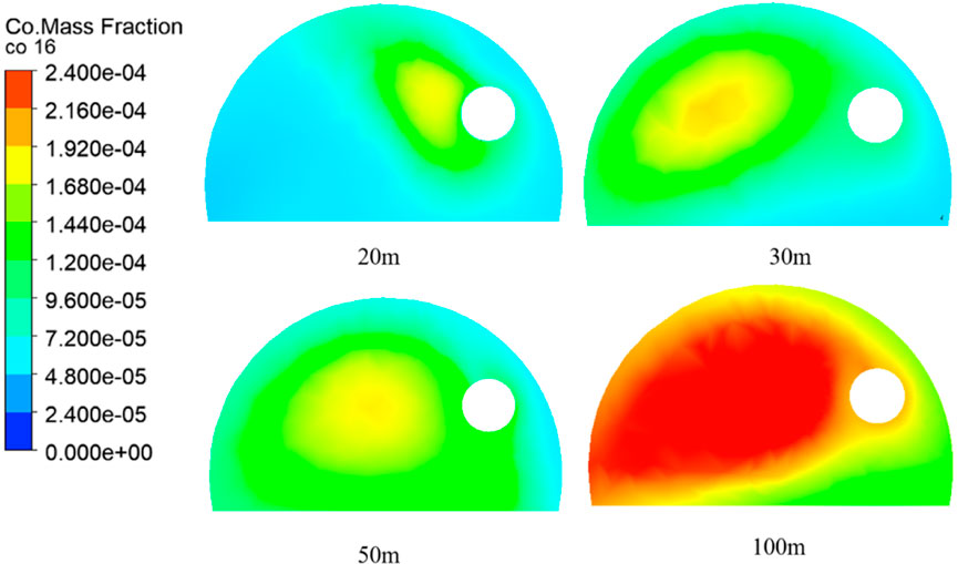
FIGURE 4. CO distribution cloud map at different distances from the palm surface at 300s.
Figure 5 describes the changes of carbon monoxide concentration in sections at different locations of the main tunnel and ventilation inclined shaft. The measuring points at 20 m and 40 m away from the outlet are 20 m and 40 m away from the portal of the ventilation inclined shaft. It can be seen from the figure that the change of carbon monoxide concentration on both sides is basically the same. With the exception of the carbon monoxide concentration at 50 m away from the face at both sides, other positions show a trend of increasing first and then decreasing.
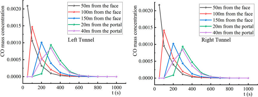
FIGURE 5. Distribution of the average carbon monoxide concentration at different locations in the equal-length tunnel.
However, the scenario of pollution and the required air volume at both sides of the tunnel being the same is very rare in the actual construction. Therefore, the CO produced by blasting at only one side is studied. When calculating, the supply wind speed of one side to must be set 10 m/s and the other side to 25 m/s. The CO diffusion law at both sides of the tunnel was investigated.
Figure 6 shows the flow field vector diagram and flow diagram in the tunnel. It can be clearly seen from the figure that the average wind speed of the main tunnel on the side with large air supply volume is larger than that on the side with small air supply volume. In addition to the eddy current near the tunnel face, there are a local eddy current region and unstable flow fields in the main tunnels on both sides. This is because of the “collision and extrusion” of airflow on both sides of the main tunnels, creating a larger range of the eddy current region. In addition, the different air supply volume also makes the range of the eddy current disturbance region on both sides of the main tunnels different.
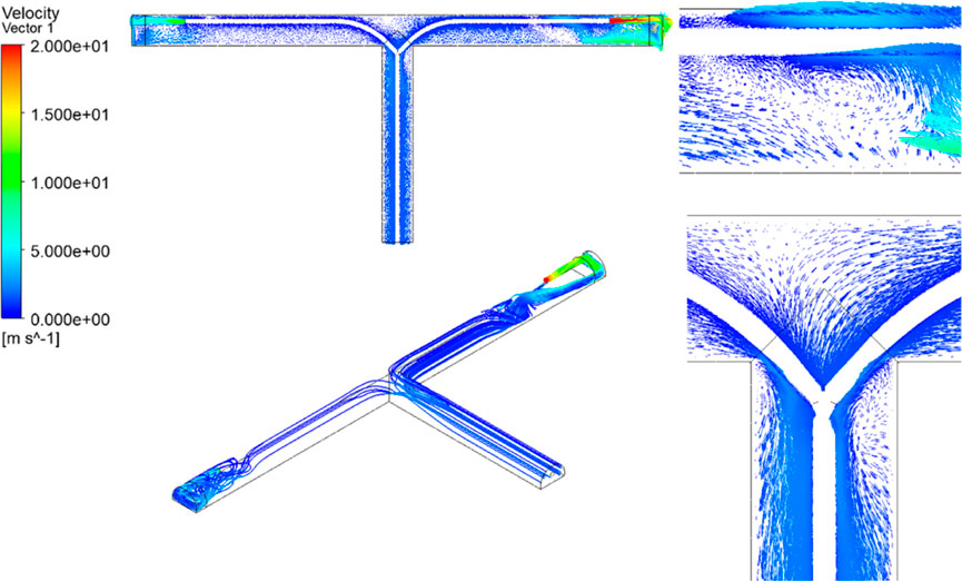
FIGURE 6. Flow field diagram of equal-length tunnel with different ventilation speeds.
The supply wind speed of one side must be reset to 20 m/s and the other side kept at 10 m/s. The CO diffusion is shown in Figure 7. It can be found that when the air supply volume of one side of the tunnel decreases, the influence of the airflow on the other side decreases, and CO can also be diffused and diluted faster. From the CO concentration cloud map, it can be seen that no serious carbon monoxide cross-flow occurs during the whole process of carbon monoxide diffusion in the right tunnel, and only a small amount of CO accumulation occurs at the intersection near the left tunnel after 125 s. The carbon monoxide in the tunnel is basically discharged at 325 s.
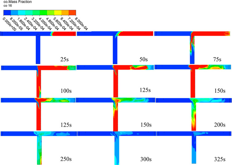
FIGURE 7. CO diffusion during single-end blasting in equal-length tunnels.
4.3 Study on dust diffusion law in construction of equal-length tunnel at both sides
Figure 8 shows tunnel dust dispersion and transport at different moments of slurry spraying. It can be seen that with the continuous progress of the slurry spraying process, the dust concentration in the tunnel gradually increases and gradually diffuses outside the tunnel following the airflow direction. The dust distribution of the palm surface of the two tunnels is relatively symmetrical. The dust produced by both sides of the palm faces reaches the intersection at 200 s and migrates together to the ventilation inclined shaft. There is a high concentration of dust accumulations at several time points at 30 m–60 m away from both sides of the palm surface, which is due to the existence of the eddy current region and low wind speed, resulting in the accumulation of dust particles nearby. The dust concentration in the tunnel tends to be stable, and the dust concentration distribution does not change much after 400 s, showing the distribution law that the dust concentration near the palm surface is large, and the concentration closer to the tunnel exit is smaller.
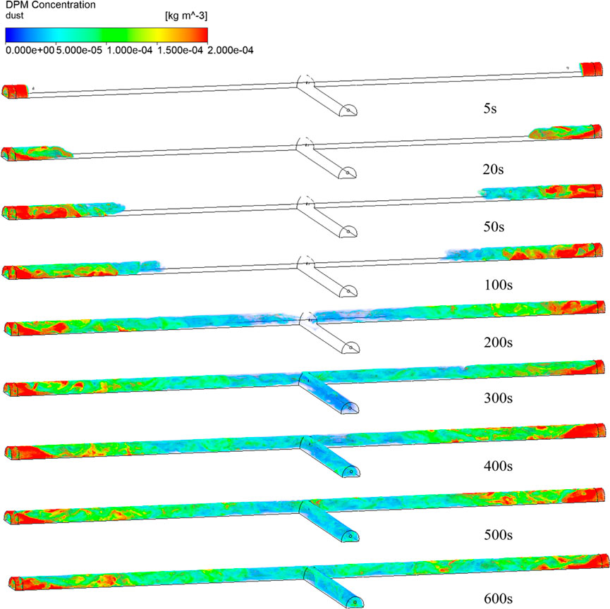
FIGURE 8. Three-dimensional cloud map of tunnel dust dispersion and transport at different moments of slurry spraying.
It can be seen intuitively in the dust concentration distribution near the palm surface (Figure 9) that a large amount of dust near the palm surface gradually settles to the tunnel floor, and the concentration distribution shows a stepped distribution. However, the dust farther away from the palm surface does not settle more significantly. This is because the dust that can move with the airflow has less mass and is difficult to settle, resulting in most of it being carried out of the tunnel with the fresh airflow. Figure 10 shows the dust concentration distribution of 10 m, 30 m, 50 m, and 100 m from the palm surface on both sides of the tunnel. It can be seen that the dust distribution law in the tunnel is roughly similar. The farther the distance from the palm surface, the lower the dust concentration, and this shows the characteristics of higher dust concentration at the bottom. This is also because the dust produced by the slurry spraying contains a large amount of large particle dust, which naturally settles to the bottom of the tunnel under the action of gravity. A small amount of dust moves with the flow direction of the wind, so the dust distribution concentration is higher near the wind duct, while the dust concentration is lower in the part away from the wind duct. That is to say, where the wind speed is higher, the dust concentration is lower.
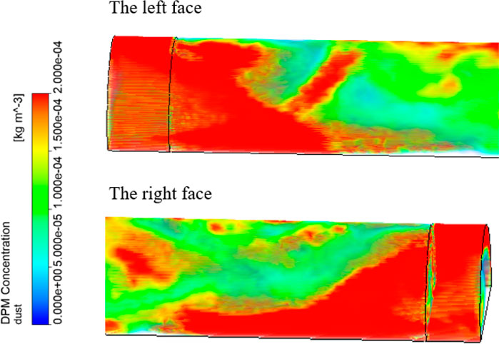
FIGURE 9. Dust concentration distribution near the palm surface on both sides.
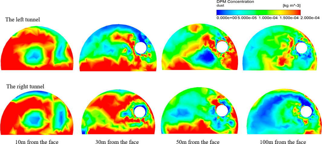
FIGURE 10. Distribution of dust concentration in the two tunnels at different distances from the palm face at 600 s.
When the tunnel length at both sides of the main tunnel is equal, the dust diffusion law at both sides is basically similar, and the dust concentration near the palm surface is always about 200 mg/m3, which exceeds the standard concentration stipulated by the state. Therefore, in the actual construction, it can not only rely on the ventilation system but through spraying water, air curtain dust removal, and other ways of reducing the dust concentration around the staff.
5 Study on the law of pollutant diffusion in a non-equal-length tunnel at both sides
During the construction period, it is very rare that the tunnel lengths at both sides of the tunnel are equal. The change of length directly affects the change of ventilation resistance and the airflow at both sides of the tunnel. This section investigates the migration and diffusion law of dust and CO when the two sides of the main tunnel are of different lengths.
5.1 Study on CO diffusion law in a non-equal-length tunnel at both sides
In order to study the influence of different lengths of the main tunnel on the ventilation efficiency of the tunnel under construction, two working conditions must be set, as shown in Tables 4, where the right tunnel is 100 m and the left tunnel is 200 m, and the carbon monoxide emission efficiency of the right tunnel must be compared when the length of the left tunnel is different.
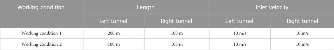
TABLE 4. Non-equal length tunnel carbon monoxide diffusion conditions.
Figure 11 describes the variation curve of carbon monoxide concentration in the central axis of human breathing height at 50 s–700 s. Comparing the concentration changes of the right tunnel under the two working conditions, it can be seen that when the length of the left tunnel and right tunnel are equal, the peak concentration at 50 s is located 38 m away from the palm surface of the right tunnel, and the peak mass fraction is 0.00339, and when the length of the left tunnel is twice that of the right tunnel, the peak concentration at 50 s is 0.00359, which is 25 m away from the palm surface of the right tunnel, showing that the diffusion speed of carbon monoxide is slower when the length of the left tunnel is lengthened. Compared with the mass fraction of carbon monoxide at other times, the CO concentration in the right tunnel is higher when the length of the left tunnel is longer. According to the analysis of the working condition in Figure 11A the distribution of CO after 200 s is relatively uniform, and there is no obvious peak value, as shown in Figure 11B. In other words, when the tunnel is longer, the CO diffusion speed at both sides of tunnel and the ventilation efficiency will be reduced.
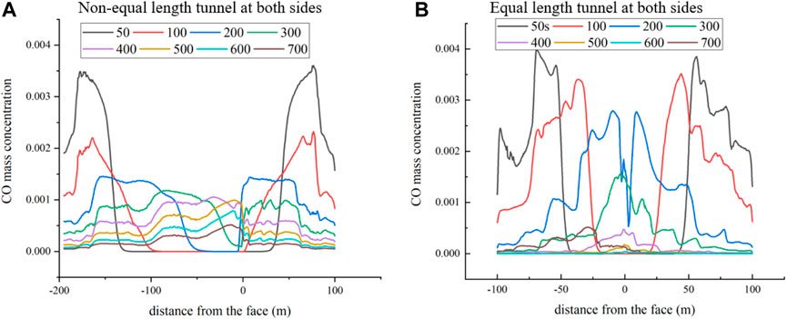
FIGURE 11. Variation of carbon monoxide concentration in the central axis of human breathing height in multi-palm surface tunnels at different moments.
5.2 Study on dust diffusion law in a non-equal-length tunnel at both sides
When both sides of the non-equal length tunnel spray dust at the same time, the dust distribution and diffusion situation is similar to that of the equal-length tunnel analyzed above, and the distribution situation at different times is shown in Figure 12. Under the action of gravity, dust with large particles and heavy mass gradually settles to the bottom of the tunnel. At the same time, the dust with a small particle size is not uniformly diffused with the airflow, but under the action of adsorption between the dust, it gathers and attracts each other to form a larger “dust mass” that also settles under gravity, and only a small part of the small particle dust diffuses with the airflow. It can be seen from the figures of 500 and 600 s that there is more dust mass near the tunnel wall and the wind duct outer wall, indicating that dust moves close to the wall when it migrates in the tunnel. There is less dust mass in the ventilation inclined shaft. The closer to the palm surface, the higher the dust concentration is, and the closer to the ventilation incline, the lower the dust concentration and the less large dust.
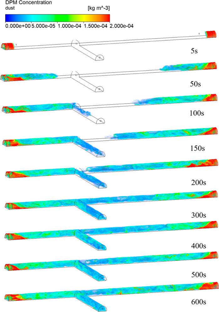
FIGURE 12. Three-dimensional dispersion distribution of dust in non-equal-length tunnels at different moments.
The region that is within 25 m of the palm surface at both sides of the tunnel is called the rapid settling region of dust, where a large number of large dust particles settle to the ground and no longer raise. From the whole process of slurry spraying, the diffusion situation of the non-equal-length tunnel is basically the same as that of the equal-length tunnel. Although the airflow in the non-equal-length tunnel becomes more unstable due to the difference in distance, the dust is less affected by the airflow during the diffusion process, resulting in the tunnel length having less influence on the dust diffusion. In addition, there is a case of one side of the pollutant flowing to the other palm surface, but overall, the impact is small.
6 Conclusion
It is more and more common to excavate multiple faces at the same time in tunnel construction. When multiple different processes are carried out at the same time, the construction environment in the tunnel is more complicated, and the ventilation systems interfere more greatly with each other, which is not conducive to tunnel ventilation. At the same time, there may be channeling to other branch tunnels, polluting the working environment of other branch tunnels and increasing difficulties for the working environment in the tunnel. Therefore, this study focuses on the construction ventilation of multiple-face tunnels, and the main conclusions are as follows:
It is found that the concentration of carbon monoxide and dust is symmetrical when the tunnel length and ventilation condition are the same. In the process of carbon monoxide migration, carbon monoxide is gradually discharged to the inclined shaft in the form of high-concentration “air mass,” and the influence of tunnel wall resistance on its diffusion is significant. The influence of concentrations of carbon monoxide on each other is not obvious during a situation of single-end blasting and different air supplies at both sides.
In the non-equal-length tunnel, the dust diffusion change is not obvious, the tunnel length has little influence on the dust settlement and diffusion, and the dust concentration cannot be effectively reduced by simple ventilation. In addition, increasing the length of the tunnel at one side will reduce the diffusion rate of carbon monoxide at the other end, reducing the rate of discharge of gaseous pollutants.
In view of the increasing employment of multiple-face tunnel construction, future research should maintain an eye on the shunt of airflow and the traction of pollutants. There are many ways to control the airflow in the duct, including the air-box and damper methods. Fresh airflow can enter the face according to demand, and dirty air can also quickly enter the ventilation branch tunnel.
Data availability statement
The raw data supporting the conclusion of this article will be made available by the authors, without undue reservation.
Author contributions
ZZ: Writing–review and editing. RL: Writing–original draft. ML: Writing–original draft. KW: Writing–original draft. SZ: Writing–review and editing. JJ: Writing–review and editing. JZ: Data curation, Writing–review and editing.
Funding
The author(s) declare financial support was received for the research, authorship, and/or publication of this article. This work was supported by State Key Laboratory of Coal Mine Disaster Dynamics and Control (2011DA105287-MS202122) and Chongqing Science and Technology Bureau (CSTB2022NSCQ-MSX1595).
Conflict of interest
Author ZZ was employed by China 19th Metallurgical Corporation. Authors ML and KW were employed by Chongqing City Construction Investment (Group) Co., Ltd. Authors SZ and JJ were employed by Zhonghuan Construction Co., Ltd. Author JZ was employed by China Huaneng Group Co., Ltd.
The remaining author declares that the research was conducted in the absence of any commercial or financial relationships that could be construed as a potential conflict of interest.
Publisher’s note
All claims expressed in this article are solely those of the authors and do not necessarily represent those of their affiliated organizations, or those of the publisher, the editors and the reviewers. Any product that may be evaluated in this article, or claim that may be made by its manufacturer, is not guaranteed or endorsed by the publisher.
References
Cao, Z. (2016). Study on ventilation characteristics and key Technologies of long tunnel and complex underground engineering construction. China: Southwest Jiaotong University.
Chen, H. (2022). Study on combined construction ventilation of separated roadway and air duct in long tunnel. [M].
Dou, X., and Chen, Q. Application of wind chamber relay ventilation in long inclined shaft tunnel construction [J]. Tunn. Constr., 2011, 31(01): 104–109.
Fang, Q., Liu, X., Zeng, K., Zhang, X., Zhou, M., and Du, J. (2022). Centrifuge modelling of tunnelling below existing twin tunnels with different types of support. Undergr. Space 7 (6), 1125–1138. doi:10.1016/j.undsp.2022.02.007
Fang, Y., Fan, J., Kenneally, B., and Mooney, M. (2016). Air flow behavior and gas dispersion in the recirculation ventilation system of a twin-tunnel construction. Tunn. Undergr. Space Technol. 58, 30–39. doi:10.1016/j.tust.2016.04.006
Guoping, X. Construction technology of combined ventilation of separated roadway and air duct in long tunnel [J]. Mod. Tunn. Technol., 2015, 52(06): 184–189.
Haas, A., Weber, A., Dorer, V., Keilholz, W., and Pelletret, R. (2002). COMIS v3.1 simulation environment for multizone air flow and pollutant transport modelling. Energy Build. 34 (9), 873–882. doi:10.1016/s0378-7788(02)00062-2
Hargreaves, D. M., and Lowndes, I. S. (2007). The computational modeling of the ventilation flows within a rapid development drivage. Tunn. Undergr. Space Technol. 22 (2), 150–160. doi:10.1016/j.tust.2006.06.002
He, X. Y., and Jiang, Y. (2018). Review of hybrid electric systems for construction machinery. Automation Constr. 92, 286–296. doi:10.1016/j.autcon.2018.04.005
Lang, J. L., Zhou, Y., Cheng, S., Zhang, Y., Dong, M., Li, S., et al. (2016). Unregulated pollutant emissions from on-road vehicles in China, 1999-2014. Sci. Total Environ. 573, 974–984. doi:10.1016/j.scitotenv.2016.08.171
Li, R., Meng, Y., Fu, H., Zhang, L., Ye, X., and Chen, J. (2018). Characteristics of the pollutant emissions in a tunnel of Shanghai on a weekday. J. Environ. Sci. 71, 136–149. doi:10.1016/j.jes.2017.11.015
Li, X., Yang, Q., Jiang, Y., et al. Research on ventilation simulation and calculation of wind bunker construction in underground cavers [J]. Chin. J. Undergr. Space Eng., 2015, 11(02): 462–468.
Li, Y., Wang, Y., Yang, C., et al. Research on ventilation technology of Jinguashan Long tunnel construction of Xiang-Putian Railway [J]. Railw. Constr., 2013, (11): 73–75.
Lin, T. L., Wang, L., Huang, W., Ren, H., Fu, S., and Chen, Q. (2017). Performance analysis of an automatic idle speed control system with a hydraulic accumulator for pure electric construction machinery. Automation Constr. 84, 184–194. doi:10.1016/j.autcon.2017.09.001
Liu, G. Application of small air chamber relay ventilation in the construction of diversion tunnel inclined shaft into main tunnel [J]. Tunn. Constr., 2013, 33(09): 785–790.
Liu, M. J., Deng, Q., Zhao, F., and Liu, Y. (2012). Origin of hydrogen sulfide in coal seams in China. Saf. Sci. 50 (4), 668–673. doi:10.1016/j.ssci.2011.08.054
Liu, R., et al. (2020). Tunnel construction ventilation frequency-control based on radial basis function neural network. Automation Constr., 118. doi:10.1016/j.autcon.2020.103293
Liu, R., Jiang, D., Chen, J., Ren, S., Fan, J., and He, Y. (2023). Blasting dust diffuse characteristics of spiral tunnel and dust distribution model: similar experiment and numerical modeling. Environ. Sci. Pollut. Res. 30 (18), 52340–52357. doi:10.1007/s11356-023-25422-w
Luo, G., Chang, L., Jia, H., et al. Study on optimization of ventilation parameters of air bin in long highway tunnel [J]. Constr. Technol., 2020, 49(23): 57–60.
Luo, Y., Han, J., Wen, Z., et al. Optimization analysis of construction ventilation scheme of Jinjiazhuang Long Spiral tunnel [J]. Tunn. Constr. Chin. Engl., 2019, 39(S1): 385–391.
Ma, L. H., Jiang, X., Chen, J., Zhao, Y. F., Liu, R., and Ren, S. (2021). Analysis of damages in layered surrounding rocks induced by blasting during tunnel construction. Int. J. Struct. Stab. Dyn. 21 (07), 2150089. doi:10.1142/s0219455421500899
Rao, A. M., Ramalingeswarudu, S., and Venkateswarlu, G. (2015). “Planning of ventilation requirements for deep mechanised long wall faces - a case study of adriyala longwall project of the singareni collieries company limited (sccl),” in Global challenges, policy framework and sustainable development for mining of mineral and fossil energy resources (GCPF) (INDIA: Mangalore).
Rodriguez, R., Diaz-Aguado, M. B., and Lombardia, C. (2012). Compensation of CH4 emissions during tunneling works in Asturias: a proposal with benefits both for local councils and for the affected population. J. Environ. Manag. 104, 175–185. doi:10.1016/j.jenvman.2012.03.020
Rodriguez, R., and Lombardia, C. (2010). Analysis of methane emissions in a tunnel excavated through Carboniferous strata based on underground coal mining experience. Tunn. Undergr. Space Technol. 25 (4), 456–468. doi:10.1016/j.tust.2010.02.010
Shan-shi, Y., Chang, L. I. U., and Luo, G. Study on optimization of ventilation scheme of inclined shaft and positive tunnel in ultra-long highway tunnel [J]. China Foreign Highw., 2022, 42(01): 187–192.
Shao, S., Yang, X. G., and Zhou, J. W. (2016). Numerical analysis of different ventilation schemes during the construction process of inclined tunnel groups at the Changheba Hydropower Station, China. Tunn. Undergr. Space Technol. 59, 157–169. doi:10.1016/j.tust.2016.07.007
Song, J., Wan, X., and Guo, C. Study on ventilation scheme of anding tunnel of yumo railway [J]. Mod. Tunn. Technol., 2020, 57(05): 232–238.
Tao, Y. C., Hu, H., Zhang, H., Zhang, G., Hao, Z., and Wang, L. (2022). A new ventilation system for extra-long railway tunnel construction by using the air cabin relay: a case study on optimization of air cabin parameters length. J. Build. Eng. 45, 103480. doi:10.1016/j.jobe.2021.103480
Zhao, D. P., Tu, H., He, Q., and Li, H. (2023). Research on the design and construction of inclined shafts for long mountain tunnels: a review. Sustainability 15 (13), 9963. doi:10.3390/su15139963
Keywords: tunnel during construction, multiple faces, transport law of pollutants, mutual interference, environmental improvement
Citation: Zhou Z, Liu R, Liu M, Wang K, Zhou S, Jia J and Zhao J (2023) Pollutant diffusion in multiple-face tunnel construction: theoretical analysis and numerical validation. Front. Earth Sci. 11:1279456. doi: 10.3389/feart.2023.1279456
Received: 18 August 2023; Accepted: 10 November 2023;
Published: 28 December 2023.
Edited by:
Faming Huang, Nanchang University, ChinaReviewed by:
Feihong Gao, The University of Hong Kong, Hong Kong SAR, ChinaJian Duan, Hunan Institute of Engineering, China
Copyright © 2023 Zhou, Liu, Liu, Wang, Zhou, Jia and Zhao. This is an open-access article distributed under the terms of the Creative Commons Attribution License (CC BY). The use, distribution or reproduction in other forums is permitted, provided the original author(s) and the copyright owner(s) are credited and that the original publication in this journal is cited, in accordance with accepted academic practice. No use, distribution or reproduction is permitted which does not comply with these terms.
*Correspondence: Rong Liu, bGl1cm9uZzExMjM1OEAxNjMuY29t