 Guohui Liu
 Pingsheng Jia2
- 1Design Institute of Appraisal and Strengthening of Shandong Jianzhu University Co Ltd, Jinan, China
- 2The Second Construction Co Ltd of China Construction Seventh Bureau, Suzhou, China
- 3School of Civil Engineering, Shandong Jianzhu University, Jinan, China
In recent years, due to the changing climate conditions and the continuous deepening of water resource conservation measures, the groundwater level in northern China has gradually risen, leading to the increasingly prominent issue of anti-floating in existing buildings and structures. The development and adoption of reliable anti-floating reinforcement techniques for existing structures are crucial for ensuring the quality of such reinforcements. Therefore, focusing on the limitations of the anchor method for anti-floating reinforcement, this paper proposes a new type of anti-floating prestressed compression anchor that features a full-length anti-compressive steel pipe with a bearing body at the end and uses non-bonding tendons throughout its length. Firstly, the structural form of this pressure-type anchor is introduced; subsequently, combined with the results of on-site pull-out tests of the anchor, an analysis is conducted on the working principle, lateral resistance distribution, and internal force transfer mechanism of the new anti-floating anchor, and its load-bearing characteristics are elucidated. Finally, relying on actual anti-floating reinforcement projects and through numerical calculations, the changes in internal forces under different anti-floating conditions of existing structures reinforced with the new anchor compared to conventional anchors are contrasted. Research findings and engineering practice indicate that this new anti-floating anchor improves the mechanical performance of the grout body of the anchor, solves the water seepage problem at the anchor location of the waterproof slab, effectively suppresses cracking of the foundation waterproof slab after reinforcement, and enhances the anti-floating and durability of existing structures.
1 Introduction
Since the early 1990s, a large number of underground structures have been constructed in northern China. Due to factors such as lower precipitation and excessive groundwater exploitation at that time, the groundwater level in cities of northern China was generally low. Many designs of underground structures at this time were inadequately considered or not considered for anti-floating stability. But in recent years, the groundwater level in northern China has been rising year by year. There are two reasons for this phenomenon. Firstly, the increment of rainfall recharges the underground water. Secondly, the protection policy of groundwater has been gradually tightened. Especially during the rainy season in years of abundant rainfall, the groundwater level in many areas has increased significantly compared to previous years (e.g., in 2021, the groundwater level in certain areas of Jinan has risen by more than 20 m compared to previous years). As a result, many underground structures were floated up or cracking of waterproof slabs. The above forms of damage have frequently occurred in recent years.
Compared with newly constructed structures, the choice of anti-floating methods for existing structures may be constrained due to limitations related to the current usage status of the structure, engineering geological and hydrogeological conditions, as well as on-site construction conditions. There are primarily three methods used for anti-floating reinforcement of such foundation types: weighting for anti-floating, water interception and pressure reduction methods, and the method of anti-floating piles and anti-floating anchors (Zheng et al., 2004; Yuan, 2007). The weighting method is simple in technique, but when adding weight to the top of an underground structure, one must consider the outdoor site elevation and the load-bearing capacity of the roof slab; whereas adding weight to the slab bottom may affect the useable space of basements. Water interception and pressure reduction methods (Cao et al., 2016) require long-term maintenance, and their reliability and durability over extended service life are difficult to ensure. Although anti-floating piles have high pullout resistance, their construction may cause damage to the existing foundation slab, and the equipment required for construction is not easily adaptable for indoor reinforcement project, hence these methods only used for outdoor underground structures like swimming pools and large water tanks (Han et al., 2009). Anti-floating anchor methods offer flexible arrangements, higher pullout resistance, strong adaptability to different strata, and compared to anti-floating piles, anchors need smaller opening of slab than piles that reduce damage to the foundation slab and disturbance to the subgrade, making them widely used in anti-floating reinforcement projects.
Currently, conventional anti-floating anchors are divided into tension-type and pressure-type. Tension-type anchors transmit loads through the bond between the anchor body (steel bar or steel strand) and the grout in the anchorage section, but tension on the anchor may cause cracking of grout bodies (Chen, 2024), leading to reduced durability. Pressure-type anchors transfer the tension directly from the anchor to the end of bearing body, which under traction, compresses the front-end grout body. During the hole life of the anchor, the grout body remains in a state of compression, avoiding tensile cracking, and thus their load-bearing capacity and durability performance are superior to tension-type anchors (Li et al., 2007). However, it should be noted that when reinforcing independent foundations with waterproof slabs using additional pressure-type anchors, the prestressed load directly act on the existing waterproof slab, changing its stress state and potentially causing insufficient bottom reinforcement, downward deflection, and cracking failure, leading to slab water leakage and reduced durability. Moreover, waterproofing around the holes made in the waterproof slab is also an urgent engineering issue that needs addressing. Therefore, the development and application of new anti-floating anchor technologies for existing underground structures is an important task for engineering technicians.
To address these engineering problems, this paper proposes and introduces a new type of anti-floating anchor. Combining the results of on-site pullout tests of the anchor, analyses are conducted on the working principle, lateral resistance distribution, and internal force transfer mechanism of the new anti-floating anchor, and its load-bearing characteristics are described. Relying on actual anti-floating reinforcement projects and engineering applications, modelling analysis is performed to compare the changes in internal forces under different buoyancy conditions of existing structures reinforced with the new anchor versus conventional anchors. The reinforcement characteristics of the new anti-floating anchor are summarized, providing a reference for design advices of the new anchor.
2 Novel prestressed steel pipe anchors
2.1 Structure and construction of the new anchor
To address the problem of insufficient bending capacity at the bottom of the original waterproof slab under low water levels when conventional anchors are prestressed on existing waterproof slabs, this novel type of prestressed steel pipe anti-floating anchor was invented.
As depicted in Figure 1A, the structure of this anti-floating anchor comprises the anchor body, a bottom bearing plate with dedicated anchorage fittings, and a top bearing plate with dedicated anchorage fittings. The anchor body is constructed from a finished steel pipe and unbonded stranded wires located inside the steel pipe. At the bottom of the stranded wires, a bearing plate and dedicated anchorage fittings are used to secure them to the bottom end of the steel pipe. The bottom bearing plate is welded to the bottom end of the steel pipe, and dedicated anchorage fittings are used to anchor one end of the stranded wire bundle to the bearing plate. To ensure the durability of the bottom anchorage fittings and the ends of the stranded wires, a short steel pipe is welded over the anchorage fittings. A circular steel plate is welded at the bottom of the short steel pipe to seal it, and the short steel pipe is treated for corrosion resistance. This creates a closed space at the bottom of the bearing plate, serving to protect the lower bearing body.
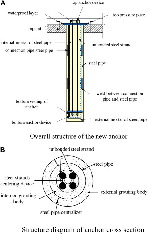
Figure 1. Anti-floating anchor structure. (A) Overall structure of the new anchor. (B) Structure diagram of anchor cross section.
The annular space between the steel pipe and the borehole wall, as well as the gap between the steel pipe and the unbonded strands, are thoroughly filled with cement mortar, as illustrated in Figure 1B. Upon the grout attaining the designated strength, a top compression plate and anchorage system are installed. Thereafter, prestressing force is applied to the strand bundles in accordance with the design specifications, and the strands are locked in place with the prestressing force equivalent to the characteristic load-bearing capacity of the anti-floating anchors. Above the existing waterproof slab, a cast-in-place reinforced concrete composite layer of a certain thickness, determined by calculation, is constructed. This layer is made to spread loads to the original waterproof slab through structural integration techniques such as concrete surface preparation and dowel bar insertion.
Additionally, when installing anchors in existing underground structures, the height of the basement space often restricts the construction of anchors. The steel pipe must be lowered into the hole in sections and then connected. In this new type of anchor, the stranded wires can be inserted into the hole in one go, ensuring their integrity and not affecting the stress transfer. The steel pipe is constructed in segments according to the on-site clearance height, with adjacent sections welded together using steel sleeves.
2.2 Waterproofing measures for waterproof slabs and anchors
When adding anti-floating anchors to existing underground structures, the junction between the waterproof slab and the anchor, as well as the anchor itself, are weak points prone to leakage, which can affect the use of the underground structure and the durability of the anti-floating structure. Therefore, appropriate waterproofing measures must be taken for the weak parts of the waterproof slab and the anchor.
Waterproofing measures include those for the anchor itself and for the joint between the waterproof slab and the anchor. The waterproofing of the anchor itself in this project is robust, mainly due to the application of an anti-corrosion lubricant on the exterior of the stranded wires inside the anchor and wrapping them with extruded high-density polyethylene resin sheathing. Additionally, the stranded wires are located within the grouting body inside the steel pipe, ensuring that groundwater cannot penetrate along the stranded wires. The bond between the grout body of the anchor and the original waterproof slab is relatively weak; hence, a micro-expansive agent is added to the cement mortar to prevent cracking at the interface due to shrinkage of the grout body. Furthermore, a cement-based penetrating crystalline waterproof coating is applied at the top of the anchor, and the anchor head is enclosed within the new concrete composite layer (as seen in Figure 2). During the construction of the new waterproof slab, integral casting is performed to avoid water leakage at the openings in the original waterproof slab, thereby enhancing the waterproof performance of the reinforcement project.
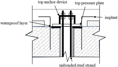
Figure 2. Design of anchor waterproof.
2.3 Interaction mechanism of the new anchor and waterproof slab
Under low water level conditions, the pre-stress is borne by the anchor itself. The downward force exerted by the bearing plate acts on the steel pipe and the grout inside and outside the steel pipe. The anchor body behaves like a miniature steel pipe pile, possessing significant vertical compressive load-bearing capacity, relieving the waterproof slab from the applied pre-load; this avoids the additional internal forces generated in the original waterproof slab when conventional pressure-type anchors are pre-stressed.
When the groundwater level rises, the bottom of the waterproof slab experiences an increase in buoyancy due to the water level. At this point, the stress distribution in the waterproof slab is consistent with that under conventional prestressed anchors. Throughout the process, the grout body of the anchor remains in compression without cracking, ensuring the durability of the anchor.
3 Field testing
3.1 Basic test of anchors
Based on the practical project mentioned in Chapter 4 of this paper, the basic test of the new anti-floating anchor is carried out. Field testing was conducted on three test anchors to determine their tensile load-bearing capacity and basic performance. The test sites were chosen in areas with relatively uniform rock layers, with the total length of the anchor body is 6.5 m, which 6 m below the waterproof slab. The diameter of the anchor is 220 mm, the design pull-out capacity of the anchor is 600 kN.Test anchors were constructed using the same techniques as the actual anti-floating anchors on site, and loading tests were performed 28 days after the completion of anchor construction. The methods of loading and unloading, displacement measurement, and determination of ultimate load-bearing capacity for the test anchors were in accordance with the relevant provisions of the “Technical Specifications for Geotechnical Anchors and Shotcrete Support Engineering” (GB 50086-2015) (China Construction Industry Publishing House, 2013). Due to the considerable anchorage length of the anchors in this project, and provided that the strength of the anchor materials permitted, loading was carried out in 9 stages, with the maximum load set at 1200 kN. The tensile load-bearing capacities of all three tested anchors met the requirements. The typical test results of anchor 1 are shown in Figure 3. Under the maximum test load of 1200 kN, the displacement of the steel strand at the end of the three anchor contains elastic displacement and a small amount of plastic displacement. There is no relative displacement between the anchor grout body and the original waterproof slab in the test.
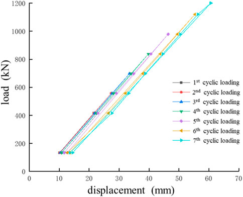
Figure 3. Basic test load-displacement curve of anchor.
3.2 Anchor lateral resistance test
To investigate the mechanical behaviour, pull-out resistance, and the distribution pattern of lateral resistance of the pressure-type prestressed anchor, an additional anchor was subjected to a tensile test. Fiber Bragg grating (FBG) strain sensors were affixed to the lateral surface of the steel pipe to measure the strain along the rod body, with the sensor arrangement depicted in Figure 4.
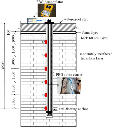
Figure 4. Sensor layout diagram.
By analysing the wavelength changes of the fibre optic sensors attached to the anchor body, as measured on-site, and utilizing Equations (1) and (2), the axial forces along different sections of the anchor under varying tensile loads can be calculated. This, in turn, allows for the computation of the corresponding lateral frictional resistances for each segment.
Where λi is the grating monitoring wavelength, λ0 is the initial wavelength of the grating, k is the strain primary term coefficient, ε is the axial strain at the monitoring position, Ni is Axial force of anchor, Esi is elastic modulus, which the steel pipe is Es=2.06×10⁵N/mm2, the mortar is Es=3×10⁴N/mm2, Ai is the respective cross-sectional area of steel pipe and mortar.
The variation curve of the axial force of the anchor along the depth under different loads is shown in Figure 5. The variation curve of the lateral resistance between the anchor and the rock under different loads is shown in Figure 6 (due to the damage of optical fibre No.④, no effective data has been obtained).
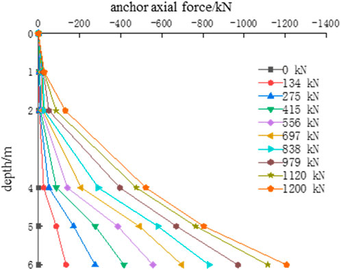
Figure 5. Anchor axial force.
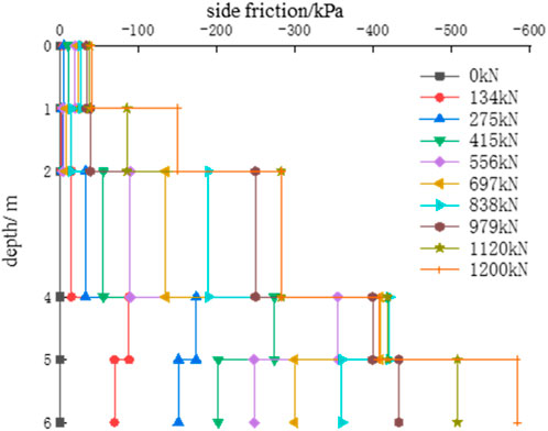
Figure 6. Anchor lateral resistance from side friction.
From Figure 6, it can be observed that under the application of tensile loads, the side resistance of the rock along the depth of the anchor varies unevenly. Initially, during the early stages of loading, the lower to middle sections of the anchor exhibit greater rock side resistance. As the applied load increases, the side resistance in these sections continues to rise; however, its relative proportion diminishes. For instance, when the tensile load is 275 kN, the combined rock side resistance between the 4 m–6 m depth is 224 kN, accounting for 81% of the total side resistance. When the tensile load reaches 697 kN, the combined rock side resistance in the same depth range is 490 kN, representing 70% of the total side resistance. At a maximum load of 1200 kN, the combined side resistance of the anchor between 4 m and 6 m depth is 684 kN, making up 57% of the total side resistance. This indicates that initially, the lower rock side resistance plays a significant role, but as the tensile load increases, the side resistance progressively engages from bottom to top.
When the maximum load value of 1200 kN is reached, the rock side resistance is 584 kPa, which is significantly below the recommended values suggested by standards. This discrepancy primarily arises because the project’s determination of anchor length considered overall failure factors, leading to a conservatively longer design length. For this individual anchor, under the application of the designed ultimate load, the rock side resistance has not yet been fully realized.
4 Engineering applications
4.1 Overview of engineering geology and hydrogeology
The strata beneath the structure base consist of moderately weathered limestone. The groundwater is primarily karst fissure water distributed within the bedrock fissures, recharged by vertical infiltration of atmospheric precipitation and lateral supply from the same aquifer. Groundwater levels are sensitive to meteorological factors and can change rapidly; the originally designed anti-floating water level was 4.5 m.
4.2 Description of the existing structure
The existing structure is a commercial complex comprising two main towers and a podium, with the above-ground portion of the main towers reaching 40 stories and the podium having 5 (locally 6) stories. There are three underground levels, with the north side and the east-west sides housing a three-story underground garage. The layout is illustrated in Figure 7. The main tower use a raft foundation, while the podium and the underground garage employ independent foundation with a waterproof slab. The concrete strength grade of independent foundations and waterproof slab is C35. The slab thickness of waterproof slab is 500 mm, using double-layer bidirectional reinforcement, with a bottom layer of φ14@200 and a top layer of φ16@200. Beneath the waterproof slab lies 500 mm of fill soil, with the slab aligned in elevation with the top of the independent foundation. Both the raft and independent foundations bear on moderately weathered limestone.
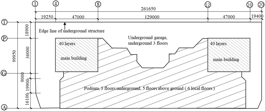
Figure 7. Basement arrangement of this project.
Construction of the project commenced in October 2012, and the main structure was completed at the beginning of 2015 before the project was halted. The project resumed at the beginning of 2019. During the hiatus, it was discovered that water levels during the high-water season were substantially higher than the original anti-floating level. Since the post-pouring strip of basements had not yet been cast, groundwater could drain through it, preventing any uplift damage to the subterranean structure. Based on the observed water level changes during the hiatus and upon re-evaluation, the total anti-floating design head was raised to 10.3 m. The original design did not meet the anti-floating requirements and necessitated reinforcement anti-floating forces.
4.3 Anti-floating reinforcement design scheme
Due to the deep burial of the underground structure in this project, the adjusted anti-floating design water level is high. Furthermore, the site is underlain by limestone with well-developed karst features, and water levels rise rapidly after rainfall. Therefore, it is impractical to employ anti-floating reinforcement measures such as interception and drainage decompression. Additionally, the top of the basement is constrained by outdoor elevation limits, and the indoor clear height is restricted by usage conditions, which also precludes the use of ballast for anti-floating reinforcement. Consequently, it has been determined that anti-floating anchors will be used for reinforcement.
Since neither the overall anti-floating capacity of the underground structure nor the stress on the waterproof slab meets the requirements, and considering the restriction of a 150 mm increase in the thickness of the waterproof slab due to the clear height of the third basement level, it has been determined, after comprehensive consideration of the above conditions, that the anchors should be installed within the waterproof slab area.
A standard column grid of 9 m×9 m is adopted for the overall anti-floating calculation. Within the standard column grid range of the pure underground garage area, the anti-floating shortfall is 5046.3 kN, while for the podium section, it is 2292.3 kN. In the pure garage area, nine anchors are arranged, with each anchor bearing an uplift resistance of 5046.3/9=560.7 kN; in the podium area, four anchors are arranged, with each rod bearing an uplift resistance of 2292.3/4=573.1 kN. The characteristic value of the uplift resistance of a single anchor is determined to be 600 kN. The arrangement of the anti-floating anchors in the underground garage area is shown in Figure 8A; the arrangement in the podium area is shown in Figure 8B.
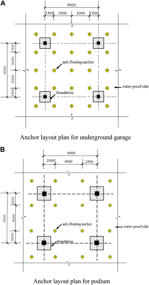
Figure 8. Standard layout of anchors. (A) Anchor layout plan for underground garage. (B) Anchor layout plan for podium.
The average uniaxial saturated compressive strength of the limestone beneath the foundation is 46 MPa, and the diameter of the prestressed anchor hole is taken as 220 mm. Due to the well-developed karst in the site, the rock failure surface is considered as a hard structural plane with poor cohesion, and the tensile strength is taken as 70 kPa based on the cohesion of the structural plane (China Construction Industry Publishing House, 2013). Considering there is a 500 mm thick soil layer beneath the waterproof slab, when the length of the anchor is 5.1 m, the minimum uplift resistance capacity is 600 kN. The actual length of the anchor selected is 6.0 m, which satisfies the capacity requirements.
The anti-floating reinforcement construction was completed in July 2021, and the whole project was put into use on 30 September 2022. In the case of more rainfall in the rainy season of the year and the higher water head of the basement waterproofing board, the deformation of the basement waterproofing board of the underground garage and the podium is normal.
4.4 Variation in waterproof slab stress after reinforcement with different anchors
In order to study the stress changes of the waterproof slab after reinforcement with different types of anti-floating anchors, the anchor arrangement of the underground garage shown in Figure 8A is used as the prototype for modelling and analysis. MIDAS GTS NX finite element analysis software is used for numerical calculation to analyse the influence of conventional anti-floating anchors and new pressure-type anti-floating anchors on the waterproof slab at low water level (i.e., without considering water buoyancy) and different water levels.
The independent foundation, surrounding rock and soil in the established model adopt 3D solid element, and the waterproof slab adopts 2D plate element. The thickness of the existing waterproof slab is 0.65 m after reinforcement construction, and the anti-floating anchor adopts 1D implantable truss element. The concrete strength of foundation and waterproof board is C35, in which the foundation size is 1.8 m×1.8 m×1.2 m, and the linear elastic model is used to simulate the elastic modulus is E=3×10⁴ MPa, Poisson’s ratio is μ=0.2, and the material weight is γ=25.2 MPa. The anti-floating anchor is 6 m long, the diameter of the ordinary anchor is d=100 mm, the diameter of the new anti-floating anchor is d=108 mm, and the rod body is steel. The linear elastic model is used to simulate the elastic modulus E=2.1×10⁵ MPa, Poisson‘s ratio μ= 0.2, material weight γ=78.5 MPa, pre-loading is N=260 kN, and the ordinary anchor does not set pre-axial force. The depth of the stratum is 8 m below the floor, of which the thickness of the surface miscellaneous fill is 1 m, and the moderately weathered limestone is 2 m. The rock and soil mass is simulated by Mohr-Coulomb constitutive model, and the parameters are shown in Table 1.
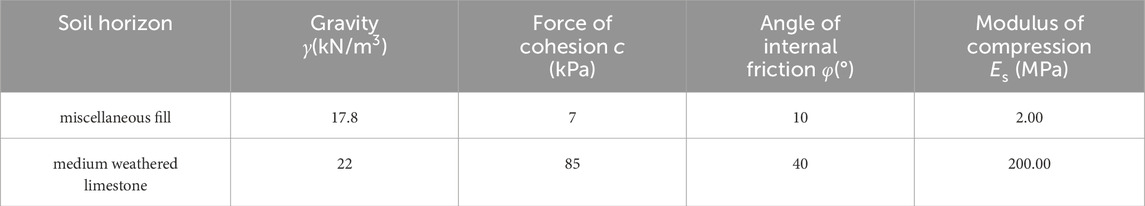
Table 1. Soil and rock parameters.
This study focuses on the stress of the waterproof slab under the action of anchor restraint and buoyancy. The displacement boundary conditions are appropriately simplified, and the displacement and vertical displacement on both sides are constrained at the bottom of the model and the bottom of the independent foundation. By applying a uniform load on the waterproof board to simulate the floating effect under different anti-floating water levels, the construction step function in MIDAS GTS NX is used to load each time the anti-floating water level rises by 2 m (i.e., the uniform load increases by 20 kPa), and the design floating water level is 0 m, 2 m, 4 m, 6 m, 8 m, 10 m respectively. The overall calculation model is shown in Figure 9.
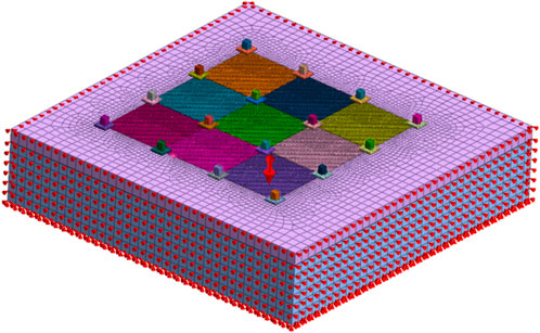
Figure 9. Calculation model of anchors.
The bending moment calculation results of the middle span of the central waterproof slab of the waterproof slab calculation model reinforced by ordinary anti-floating anchor and new anti-floating anchor are extracted, and Figure 10 and Figure 11 are drawn respectively. From the diagram, it can be seen that the bending moment distribution trend of ordinary anti-floating anchor reinforcement and new anti-floating anchor reinforcement is basically the same. With the increase of the design anti-floating water level, the bending moment distribution of each span of the new anti-floating anchor is more uniform. Under the same design anti-floating water level, the peak value of the negative bending moment of the waterproof slab reinforced by the new anti-floating anchor is smaller than that of the ordinary anti-floating anchor. The positive bending moment of the middle anchor position of the new anchor scheme is greater than that of the ordinary anchor scheme, while the positive bending moment of the anchor position on both sides shows the opposite trend. In addition, the model calculation of the conventional anchor scheme does not converge when the design anti-floating water level is 10 m. It can be considered that the anti-floating anchor and the waterproof slab have been destroyed and failed under the design anti-floating water level, while the new anchor reinforcement scheme could still bear the load without damage, and the bending moment value continues to increase, but the bending moment distribution of the waterproof slab has no significant change compared with the previous loading (
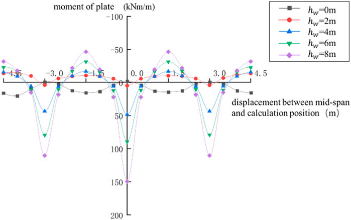
Figure 10. Moment distribution of waterproof slab reinforced by conventional anchor (kNm).
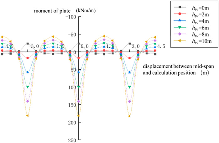
Figure 11. Moment distribution of waterproof slab reinforced by new anti-floating anchor (kNm).
5 Conclusion
With a focus on the limitations of existing anchor methods for anti-floating reinforcement, this paper proposes a new type of prestressed compression anti-floating anchor. Combining the results of on-site anchor pull-out tests, the paper analyses the load-bearing characteristics of the new anti-floating anchor. Relying on an actual anti-floating reinforcement project and based on numerical calculation results, this study compares the changes in internal forces of the existing structure under different anti-floating conditions after being reinforced with new and conventional anchors. The conclusions of this study are as follows:
(1) The new pressure-type steel pipe prestressed anti-floating anchor has a high uplift resistance capacity. Under the maximum test load of 1200 kN, it can still function normally. The steel pipe and grout form a structure similar to steel pipe concrete, which has superior compressive performance compared to conventional anchors. It will solve the anti-floating problems of insufficient reinforcement at the bottom of the existing underground structures.
(2) The new pressure-type steel pipe prestressed anti-floating anchor has good durability, simple construction operations, and is suitable for construction in narrow spaces.
(3) Engineering practice shows that the new anti-floating anchor improves the stress performance of the anchor body, this characteristic may solves the water seepage problem at the anchor location on the waterproof slab, effectively suppresses cracking of the foundation waterproof slab after reinforcement, and enhances the existing structure’s anti-floating performance and durability.
Data availability statement
The original contributions presented in the study are included in the article/Supplementary material, further inquiries can be directed to the corresponding author.
Author contributions
GL: Data curation, Formal Analysis, Funding acquisition, Resources, Writing–original draft, Writing–review and editing. PJ: Supervision, Validation, Funding acquisition, Project administration, Resources, Writing–review and editing. JS: Data curation, Formal Analysis, Funding acquisition, Project administration, Resources, Visualization, Writing–review and editing. ZJ: Investigation, Methodology, Software, Supervision, Visualization, Writing–original draft. FY: Investigation, Software, Supervision, Writing–review and editing. GY: Methodology, Supervision, Validation, Writing–original draft. GS: Software, Supervision, Resources, Writing–review and editing.
Funding
The author(s) declare financial support was received for the research, authorship, and/or publication of this article. This work was supported by the State Key Program of the National Natural Science Foundation of China [Grant No. 52038006].
Conflict of interest
Authors GL, ZJ, and FY were employed by Design institute of Appraisal and Strengthening of Shandong Jianzhu University Co Ltd.
Author PJ was employed by The Second Construction Co Ltd of China Construction Seventh Bureau.
The remaining authors declare that the research was conducted in the absence of any commercial or financial relationships that could be construed as a potential conflict of interest.
Publisher’s note
All claims expressed in this article are solely those of the authors and do not necessarily represent those of their affiliated organizations, or those of the publisher, the editors and the reviewers. Any product that may be evaluated in this article, or claim that may be made by its manufacturer, is not guaranteed or endorsed by the publisher.
References
Cao, H., Pan, H., and Luo, G. (2016). A new anti-floatation method by drainage: concept and application. Chin. J. Rock Mech. Eng. 35 (12), 2542–2548. doi:10.13722/j.cnki.jrme.2016.0343
Chen, M. (2024). Seismic response analysis of sand-rubber isolation cushion. Hefei, China: AnHui University of Science and Technology.
China Construction Industry Publishing House (2012). Code for design of building foundation. GB 50007-2011. Beijing: China Construction Industry Publishing House.
China Construction Industry Publishing House (2013). Technical code for building slope engineering; GB 50330-2013. Beijing: China Construction Industry Publishing House.
China Construction Industry Publishing House (2015). Technical code for engineering of ground anchorages and shotcrete support. GB 50086-2015. Beijing: China Plan Publishing House.
China Construction Industry Publishing House (2019). Technical standard for building engineering against uplift. JGJ 476-2019. Beijing: China Construction Industry Publishing House.
Development of the People’s Republic of China (2011). Code for design of building foundation. GB 50007-2011. Beijing: Ministry of Housing and Urban-Rural Development of the People’s Republic of China.
Han, L., Wang, D., Qu, T., and Zheng, T. (2009). Design and application of anti-floating anchored structure by blast-expanding bore in large-scale underground sewage pool. Chin. J. Rock Mech. Eng. 28 (z1), 2960–2965.
Li, Z., Zhou, X., Liu, J., Tian, T., Sun, Y., and Yin, H. (2007). Study and application of anchor rod to against floatation of high-rise building. Build. Struct. 37 (4), 55–57.
Qian, L. I. (2008). Discussion on design of the raft foundation consisting of individual footing combining with water-proof slab in Beijing. Ind. Archit. (z1), 718–720.
Wu, L. I. U., Li, N., Tan, G., and Xiong, J. (2016). Design of the independent foundation with water-proof slab. Build. Struct. (s2), 520–523. doi:10.19701/j.jzjg.2016.s2.110
Yuan, Z. (2007). Problems in design of anti-up lift in underground engineering. Chin. Jou mal Undergr. Space Eng. 3 (3), 519–521.
Keywords: existing underground structures anti-floating reinforcement, design of anti-floating reinforcement, prestressed anti-floating compression anchor, anchor field test, FBG sensor
Citation: Liu G, Jia P, Sun J, Jiang Z, Yang F, Yang G and Shao G (2024) Research and application of new anti-floating anchor in anti-floating reinforcement of existing underground structures. Front. Earth Sci. 12:1364752. doi: 10.3389/feart.2024.1364752
Received: 03 January 2024; Accepted: 05 March 2024;
Published: 21 March 2024.
Edited by:
Pengjiao Jia, Soochow University, ChinaCopyright © 2024 Liu, Jia, Sun, Jiang, Yang, Yang and Shao. This is an open-access article distributed under the terms of the Creative Commons Attribution License (CC BY). The use, distribution or reproduction in other forums is permitted, provided the original author(s) and the copyright owner(s) are credited and that the original publication in this journal is cited, in accordance with accepted academic practice. No use, distribution or reproduction is permitted which does not comply with these terms.
*Correspondence: Guangbiao Shao, c2hhb2diQHNkanp1LmVkdS5jbg==