 Lingjun Huang
 Rui Gao2
- 1Architectural Engineering Institute, Sanming University, Sanming, China
- 2School of Civil Engineering, Wuhan University, Wuhan, China
- 3Fujian Southeast Design Group Co., Ltd., Sanming, China
- 4Fujian Jinding Construction Development Co., Ltd., Sanming, China
The karst that is dominated by medium-weathered limestone and caves with various spatial features is widely distributed in the northern Fujian Province. This paper discusses the load-bearing behaviors of post-grouting tubular piles in karst region of north Fujian Province with reference to the prestressed tubular piles adopted in the residential buildings of Haixi Comprehensive Trade City Phase II Project in Sanming City. The load-settlement curve, pile side friction resistance, and pile end resistance of tubular piles are analyzed by finite element numerical simulations and field static load tests. The load-bearing behaviors of prestressed tubular piles under karst geological conditions with two different spatial features are comparatively investigated, and the effectiveness of tubular pile reinforcement is verified by field settlement observation. The results reveal that the finite element numerical model can effectively simulate the tubular pile-soil interaction. The use of pile end post-grouting of prestressed tubular piles in the karst region can significantly increase their load-bearing capacities. The top settlements of grouted tubular piles under the maximum test load can be reduced by 16.8%–22.3% compared with these of ungrouted test piles, and the theoretical simulated ultimate load-bearing capacity can be increased by 27.3%. The adoption of pile end post-grouting technique can reduce the pile end displacement of tubular piles and improve the proportion of pile end resistance. Plastic-hard plastic breccia silty clay can be used as a bearing stratum for post-grouting to achieve excellent grouting performance. The bead-shaped karst caves are more unfavorable to the exertion of load-bearing capacity of the tubular piles than the karst caves filled with plastic-hard plastic breccia silty clay to which the piles have direct access. The field monitored average settlements of the 19# and 17# buildings under karst geological conditions with two different spatial features are −12.88 mm and −8.98 mm, respectively, both of which do not exceed the warning value, indicating that it is feasible for the project to adopt the pile end post-grouting technique of the tubular piles. The achievements of this study help to further reveal the load-bearing mechanism of this type of pile, which can provide a basis for its engineering design and construction optimization.
1 Introduction
Tubular piles are widely used in soft ground (containing rockburst stratum (Lianpeng et al., 2018; Lianpeng et al., 2021; Dai et al., 2022; Yishan and Aiwen, 2023)) reinforcement due to their good quality and convenient construction (Jinjin et al., 2023). However, the pile side friction resistances are often under-exerted due to the smooth surface of the pile body. Together with the influence of adverse geological conditions, it is often necessary to reinforce the ground at the pile end by post-grouting to achieve the improvement of load-bearing capacity.
Currently, scholars mainly adopt the combination of theoretical calculations and model tests (Qi et al., 2023) or the field static load tests to study the load-bearing behaviors of tubular piles. Kou et al. (Paik and Salgado, 2004; Li et al., 2019; Xiucheng et al., 2019; Wang et al., 2020; Kou et al., 2020; Shimeng and Xinsheng, 2020; Sheng-Hua et al., 2022; Yan et al., 2022; Bo et al., 2024) studied the load-bearing behaviors of tubular piles under different geological conditions and construction methods, optimized the load-bearing capacity detection means, and proposed the methods for improving the load-bearing capacity of pile foundation. Gong et al. (Wen et al., 2020; Hou et al., 2021; Dai et al., 2023; Gong et al., 2023) carried out a study on the improvement of load-bearing capacity of tubular piles by post-grouting technique, and they analyzed the pile friction resistance and pile-soil relative displacement by changing the post-grouting position and grouting material. Gong et al. (Gong et al., 2023) used end-side joint post-grouting technique to improve the load-bearing capacity of the pile foundation. They pointed out that the post-grouting significantly increased the load-bearing capacity of the pile foundation and reduced the relative displacement required to mobilize the vertical resistance of the test pile. For the floating pile phenomenon caused by rapid pile sinking of precast tubular piles in deep saturated cohesive soil layer, Qiang (Dai et al., 2023) implemented a post-grouting reinforcement programme for prestressed concrete precast tubular piles in the field. The results showed that the post-grouting technique can effectively eliminate the unfavorable effects of floating piles, and the load-bearing capacity of a single pile was greatly improved. Hou et al. (Hou et al., 2021) optimized the proportion of cement mixture with four-factor five-level orthogonal test by using the silicate cement as raw material and water reducer as well as the expansion agent and early strength agent as additives. Accordingly, the effect of physical and mechanical properties of grouting materials on the molecular resistance and load-bearing performance of PHC piles without extruded soil was investigated. Wen et al. (Wen et al., 2020) discussed the relationship between the side friction resistance of grouted steel piles and the pile-soil relative displacement of each soil layer in marine soft clay, and the load-bearing capacity of miniature piles was improved by the post-grouting technique. The above studies on the load-bearing behaviors of different types of tubular piles with and without post-grouting technique have achieved considerable outcomes. However, the pile side friction resistance, pile end resistance, and pile-soil interaction of the widely used prestressed piles under their own characteristics still need to be further analyzed.
Tubular piles are also applicable to the soft ground reinforcement in karst region (Boyang et al., 2023). Wang et al. (Wei et al., 2017; Dong et al., 2018; Huang et al., 2019; Wang et al., 2020) analyzed the influence of different parameters such as span, thickness, pile diameter, and inclination on the load-bearing behaviors of the pile foundation. They revealed the damage mechanism of the karst cave roof and obtained the optimal calculation method of the embedded depth of the pile foundation. Tao et al. (Tao et al., 2017; Ding-Wei et al., 2018; Xiang et al., 2019; Xuefeng, 2019) investigated the effect of pile side or pile end post-grouting technique on the load-bearing capacity of pile foundation in karst region, and made comparative analyses of pile top displacement, pile side friction resistance, and pile end resistance under different loading conditions. They also made specific statements on post-grouting technique to improve the pile load-bearing capacity and to control the settlement. However, the above studies mainly focus on composite foundations reinforced by bored piles and rigid piles, but less on tubular piles. It is worthwhile to explore the similarities and differences in load-bearing behaviors between tubular piles and other types of piles in reinforcing the soft ground in karst regions.
The karst regions in northern Fujian Province are mostly dominated by moderately weathered limestone, and the spatial features of the karst caves are diverse, which can be locally bead-shaped. In this paper, the prestressed tubular piles adopted in the residential buildings of Haixi Comprehensive Trade City Phase II Project in Sanming City are taken as a reference to carry out the research. The tubular piles are located in the karst region, where karst funnels and caves are well-developed, most of the karst caves or soil caves are filled with breccia silty clay, and a few of them are empty caves. The load-settlement curves, pile side friction resistance, and pile end resistance of tubular piles are analyzed by finite element numerical simulations and field static load tests. The load-bearing behaviors of prestressed tubular piles under karst geological conditions with two different spatial features are comparatively investigated, and the effectiveness of tubular pile reinforcement is verified by field settlement observation. Numerical modelling focuses on the tubular pile-soil interaction, pile top settlement, pile end displacements, pile side friction resistance, and pile end resistance, while field static load test emphasizes on the monitoring of pile top settlement. The results demonstrate the effectiveness of the post-grouting technique. The study clarifies the unique load-bearing mechanism of these piles in the karst region of northern Fujian Province, which can provide a basis for their engineering design and construction optimization.
2 Overview of the project
The Haixi Comprehensive Trade City Phase II Project consists of 13 residential buildings and is located to the west of Shaxi River in Sanming City. The original geomorphological unit of the site is alluvial terrace. The original topography is relatively flat, open, and slightly inclined to Shaxi, which is then transformed into the current situation by artificial backfilling due to the construction of the Sanming South Station. The adverse geology of the site is mainly the basically stable soil holes and karst caves. The borehole drillings reveal that the karst action at the site is relatively strong. The development of soil holes and caves is uneven and irregular, which can be locally bead-shaped, and a few of them are empty caves. The height of the karst or soil caves is 0.90–73.40 m, and the thickness of the karst cave roof is 1.20–8.10 m. The rock mass surface of the roof varies greatly. Karst or soil caves are mainly filled with breccia silty clay (fluid-soft plastic or plastic-hard plastic), and a few of them are empty caves.
The top-to-bottom stratigraphy of the site mainly includes: miscellaneous fill with a layer thickness of 0.40–10.40 m, silty clay with a layer thickness of 0.90–8.20 m, silty fine sand with a layer thickness of 1.60–8.10 m, pebbles with a layer thickness of 0.60–10.90 m, strongly weathered siltstone with a layer thickness of 6.70–39.51 m, a few boreholes exposing cavities, breccia silty clay (flow-soft plastic), breccia silty clay (plastic-hard plastic), and moderately weathered limestone. Prestressed tubular piles are adopted for the reinforcement of the residential buildings. Given the different geological conditions of the site, the pile length ranges from 30 to 75 m, and the pile diameter is 500 mm. The pile bearing stratum is mainly plastic-hard plastic breccia silty clay. A few piles enter directly into moderately weathered limestone, which requires a post-grouting technique to reinforce the strata at the pile end.
Two typical geological features of the project site that require post-grouting reinforcement of pile foundations are as follows. (1) The pile foundations enter directly into the karst caves filled with plastic-hard plastic breccia silty clay. (2) The pile foundations directly enter the karst caves filled with plastic-hard plastic breccia silty clay after passing through the karst caves filled with flow-soft plastic breccia silty clay. The two types of karst caves within the pile length are vertically beads-shaped. The two geological profiles represented by 42-m long pile (19-2#) and 58-m long pile (17-2#) are illustrated in Figure 1.
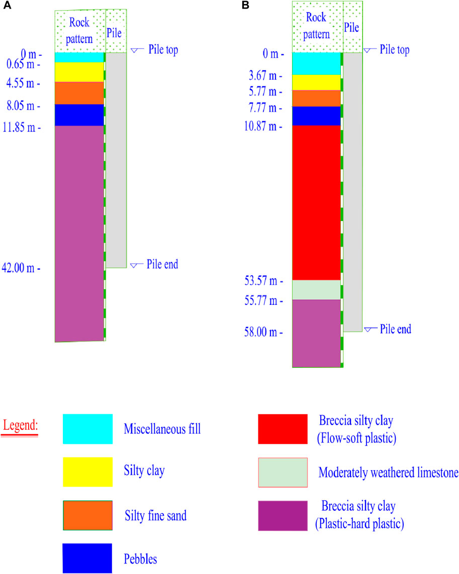
Figure 1. Spatial features of typical karst caves at the site. (A) Feature 1 (B) Feature 2.
3 Field static load test of prestressed tubular pile
3.1 Static load test programme
For the two more typical geological features at the project site that require post-grouting to reinforce the pile foundation, the foundation sites of 19# and 17# buildings are typical representatives of the geological Features (1) and (2), respectively. Three prestressed tubular piles are selected as test piles for each building. The lengths of the test piles of #19 building are 40 m (19-1#), 42 m (19-2#), and 49 m (19-3#), respectively, while those of #17 building are 60 m (17-1#), 58 m (17-2#), and 67 m (17-3#), respectively. The design diameters of all test piles are 500 mm, and the pile body is made of C80 concrete. The design load-bearing capacity of the test piles is 2,200 kN, and the maximum test load is 4,400 kN. The staged load is 1/10 of the maximum test load, i.e. 440 kN. The first-stage load is 2 times the staged load, i.e. 880 kN. Each subsequent stage load is increased by 440 kN. The unloading of each stage is taken as two times the staged load, i.e. 880 kN. The test piles are loaded by slow loading method, and the settlement is measured at 5, 15, 30, 45, 60, 90, and 120 min after each stage of load application, and the data at 120 min is taken as the stable measurement of the test. Four displacement gauges are installed symmetrically at the test pile top to measure the pile top settlement under various stages of loading (see Figure 2).
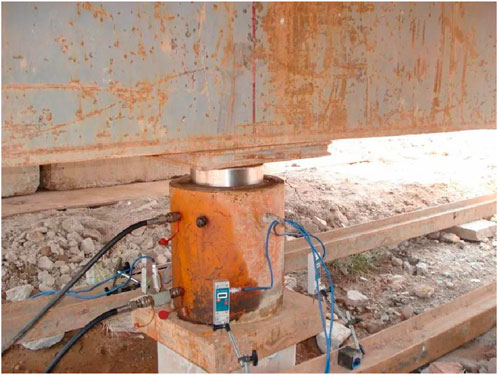
Figure 2. Picture of displacement gauge installation.
3.2 Post-grouting design
Post-grouting pile reinforcement is carried out at the pile end to improve the load-bearing behaviors of the pile bearing stratum (plastic-hard plastic breccia silty clay).
High-pressure jet grouting is utilized to inject the grout into the end of the PHC pile. The radius and height of jet grouting pile are 1.2 m and 3 m, respectively. High-pressure jet grouting is performed after the piling. Jet grouting reinforcement is performed within 3 m of the pile base by extending a high-pressure jet grouting drill rod in the center of the prestressed tubular pile to the pile base. High-pressure jet grouting adopts double-pipe technique, and the diameter of jet grouting pile is 1,200 mm. Grouting pressure is 20–30 MPa, with a water-to-cement ratio of 1.2. The grade 42.5 Ordinary silicate cement is used, with a dosage of 500 kg/m3, and the total amount of a single pile is 3t. The 40-m long pile of #19 building (19-1#) and the 60-m long pile of #17 building (17-1#) are set as the reference piles, which are not post-grouted, all pile load tests are completed, post-grouting treatments applied to 17-1# and 19-1# at a later stage.
3.3 Field test results
All the test piles are loaded to 4,400 kN. The load-settlement curves of the test piles are displayed in Figure 3. The results of the static load tests are summarized in Table 1.
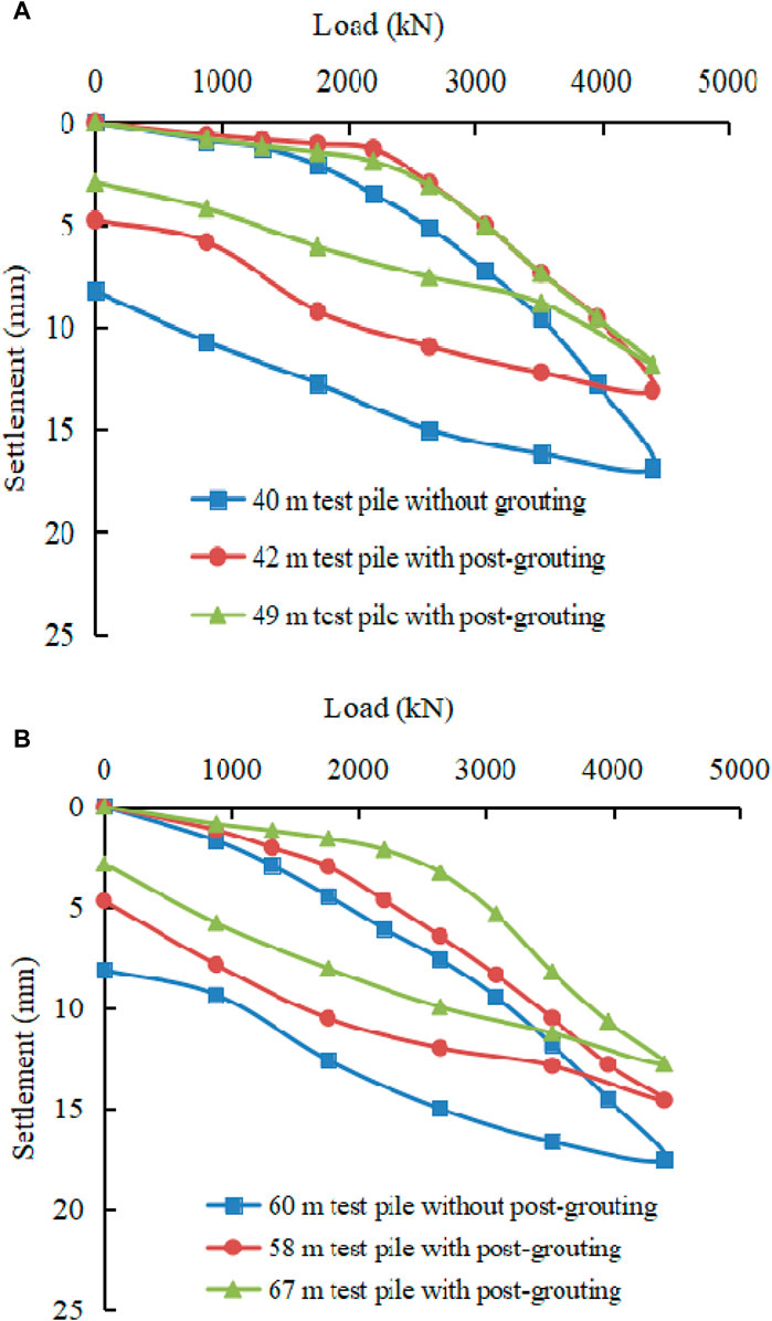
Figure 3. Load-settlement curves of the test piles. (A) Test pile of #19 building (B) Test pile of #17 building.
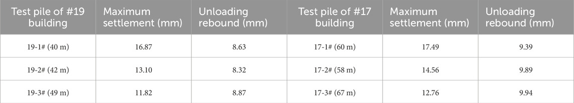
Table 1. Results of the static load tests on test piles.
Table 1; Figure 3 demonstrate that none of the test piles reach the ultimate state under the 4,400 kN. The difference between the top settlements of the grouted and ungrouted piles is not significant when the load is small, which indicates that the soil in the grouted zone has not yet exerted its load-bearing capacity. The displacement difference gradually increases with the gradual increase of load. Due to large stiffness of the C80 concrete pile body, the ultimate state is not reached under the test load condition. The tubular piles are mainly in a compression-elastic state, and the residual settlement is the sum of the pile end settlement and the plastic deformation of the pile body. The maximum settlement and unloading rebound of test piles from 1# to three# of 17# building are slightly larger than those of test piles with shorter pile lengths of 19# building, indicating that the Feature 2 with bead-shaped karst caves is more unfavorable to the exertion of load-bearing capacity of tubular piles.
For the three test piles of 19# building, the difference in length between the 19-2# (42 m) test pile with post-grouting and the 19-1# (40 m) test pile without post-grouting is relatively small, while there is a more obvious improvement in the load-bearing performance of the 19-2#, and its maximum pile top settlement is reduced by 22.3% under the 4,400 kN. The load-bearing capacity of the 19-3# test pile (49 m) under the same post-grouting condition is improved to a certain extent due to a 7-m increase in pile length compared with that of the 19-2# test pile (42 m). The maximum pile top settlement under 4,400 kN is reduced by 9.77% compared with that of the 19-2# test pile.
For the three test piles of 17# building, the difference in length between the 17-2# (58 m) test pile with post-grouting and the 17-1# (60 m) test pile without post-grouting is relatively small, while there is also a more obvious improvement in the load-bearing performance of the 17-2#, and its maximum pile top settlement is reduced by 16.8% under the 4,400 kN. The load-bearing capacity of the 17-3# test pile (67 m) under the same post-grouting condition is improved to a certain extent due to a 9-m increase in pile length compared with that of the 17-2# test pile (58 m), and the maximum pile top settlement under the 4,400 kN is reduced by 12.36% compared with that of the 17-2# test pile.
4 Numerical simulation
4.1 Model establishment
Figure 4 presents the finite element model of the pile foundation. The soil and grouted reinforcement bodies are simulated with an elasto-plastic constitutive model that obeys the Mohr-Coulomb yield criterion. Considering the influence of the soil layer around the pile and at the pile end, the horizontal range of the soil layer is taken to be not less than 10 times the diameter of the pile (taken as 20 m) in X and Y directions and about 1.5 times the length of the pile in the vertical direction. The pile body is modelled by a beam unit linear elastic model to capture the actual force characteristics. The pile-soil interface is modelled by a friction contact unit that is unique in the finite element software. The pile end is modelled by a spring unit to simulate the support. The soil body, grouted reinforcement body, and piles are automatically meshed, the size of the soil body and grouted reinforcement body does not exceed 1.7 m, while the pile beam unit is achieved through the connection of corresponding nodes in the soil body. Rz constraints are set at the boundaries of the pile elements, while normal boundaries are set around the soil elements, with fixed boundaries at the bottom and free boundaries at the surface.
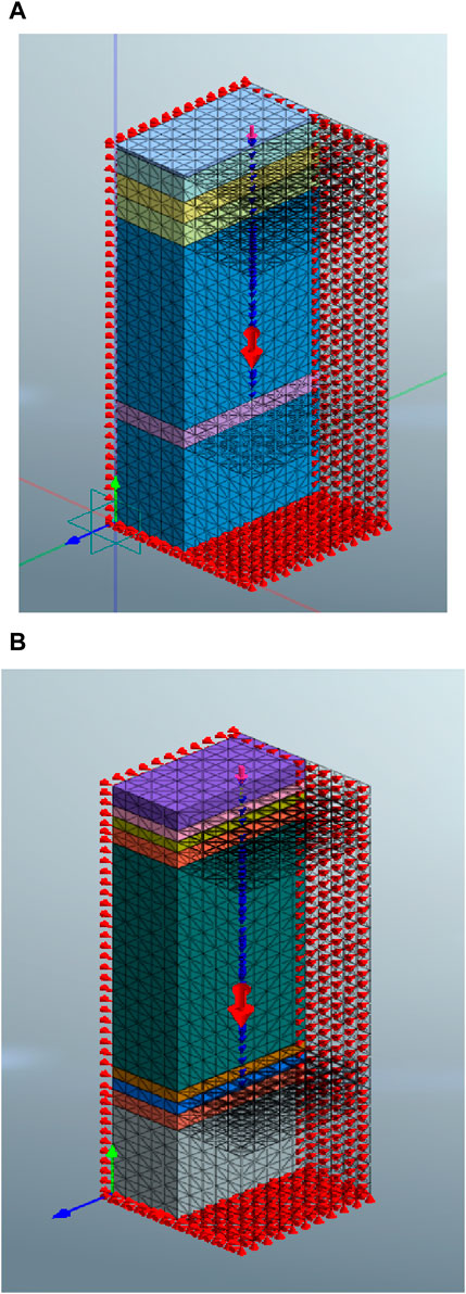
Figure 4. Finite element model of the pile foundation. (A) Test pile of 19# building (B) Test pile of 17# building.
4.2 Determination of numerical parameters
The diameters of the numerical test piles are all 500 mm, and the pile lengths are the same as the actual lengths of the test piles of the 19# and 17# buildings. The pile parameters are listed in Table 2.
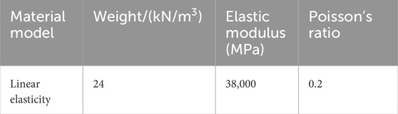
Table 2. Parameters of the piles.
The grouting process at the base of high-pressure jet grouting piles involves reinforcing the pile end area with a radius of 1.2 m and a height of 3 m. Grout is injected into the surrounding soil under high pressure, solidifying the sediment at the bottom of the pile and altering soil parameters to enhance the ultimate load-bearing capacity. Both soil and grouting reinforcement adhere to Mohr-Coulomb yield criterion, with calculation parameters derived from geological prospecting data and laboratory tests (Table 3). Due to close proximity between pile foundations on-site (average center distance approximately 1.6 m), a numerical simulation model considers soil layers within 3 m depth as part of the grouting reinforcement model. The bearing characteristics of the test pile are analyzed through numerical simulation, disregarding any variations in pile bearing capacity during the grouting process.
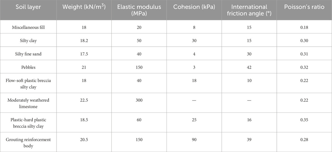
Table 3. Calculation parameters of soil and grouting reinforcement bodies.
The shear and normal stiffness moduli of the pile-soil contact surface at the pile side in the numerical simulation are 100 MPa and 300 GkN/m3, respectively. Considering the insufficient exertion of side friction resistance of the prestressed tubular piles, and combining with the standard value of side friction resistance in each soil layer provided by the geological investigation data (about 30% less than the standard value of pile side friction resistance in the same condition of grouted piles), the final shear stress is taken as 35 kPa for miscellaneous fill, silty clay, and silty fine sand, 80 kPa for pebbles, 30 kPa for flow-soft plastic breccia silty clay, 50 kPa for plastic-hard plastic breccia silty clay, and 180 kPa for moderately weathered limestone in the numerical simulation. The stiffness of the spring element at the pile bottom can be determined using the estimated pile tip reaction and the pile tip settlement ratio. The estimated pile tip reaction for ungrouted piles is 1500kN, while for grouted piles it is 2200 kN. The pile tip settlement value can be calculated by subtracting the unloading rebound from the maximum settlement of the pile in Table 1.
4.3 Analysis of numerical simulation results
Concentrated forces are applied to the piles in the numerical simulations. Non-linear control is employed in the analyses, and the loads are accumulated according to the actual load increments. Theoretical numerical calculations are performed for six test piles of 19# and 17# buildings, and the results are as follows.
4.3.1 Analysis of load-settlement curves
The numerical and monitored load-settlement curves at the pile top and at the pile end of the test piles are illustrated in Figure 5, where the test pile in the numerical model are loaded to the ultimate load. The load at which a sudden steep drop in the settlement occurs for the same load increment is considered the ultimate load point. Taking the ungrouted 19-1# and grouted 19-2# test piles as an example, the settlement nephograms of the tubular piles under 4,400 kN are displayed in Figure 6.
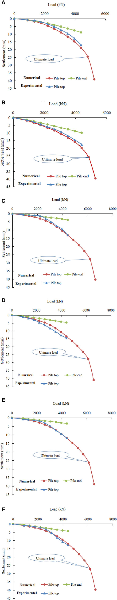
Figure 5. Load-settlement curves of the test piles at the pile top and end. (A) 19-1# test pile (B) 17-1# test pile (C) 19-2# test pile (D) 17-2# test pile (E) 19-3# test pile (F) 17-3# test pile.
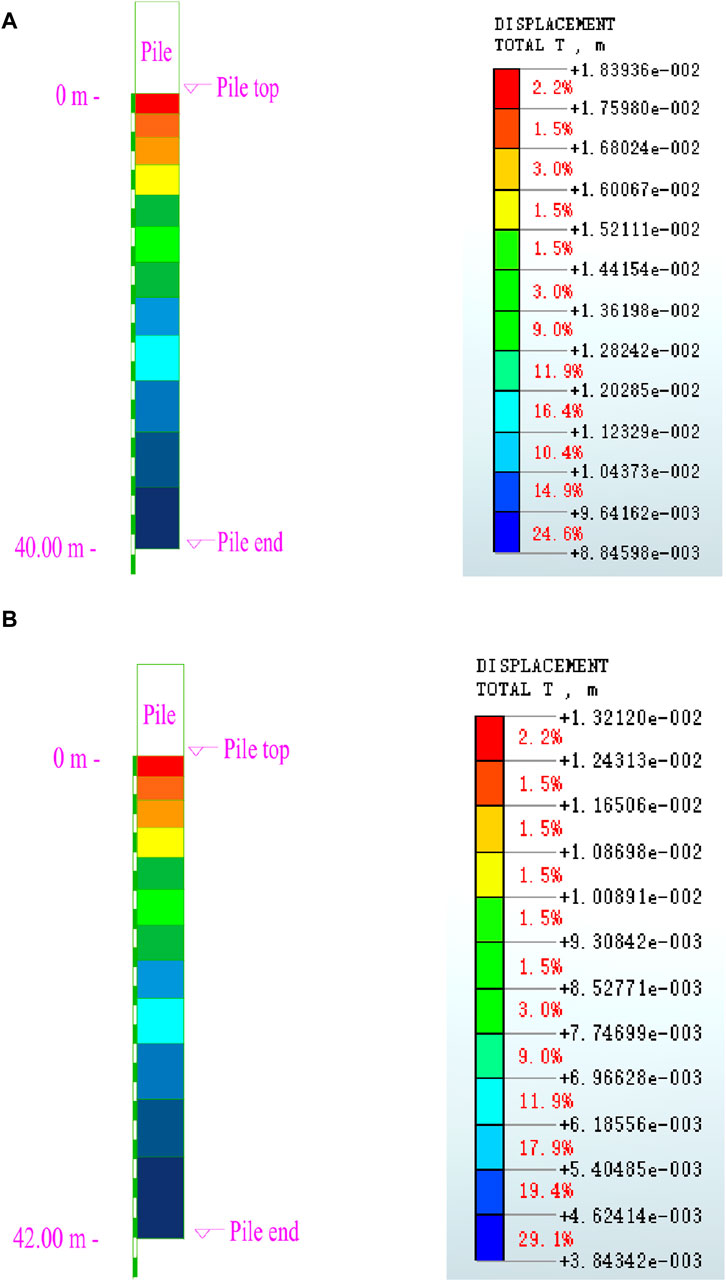
Figure 6. Settlement nephograms of the test pile under the 4,400 kN. (A) 19-1# test pile (B) 19-2# test pile.
Figure 5 demonstrates that the load-settlement curves at the pile top obtained from the numerical simulation are in good agreement with those measured in the field, indicating that the calculation parameters of the pile body, soil body, and grouting reinforcement body adopted in the numerical simulation are reliable. However, the numerical values are slightly larger than the measured values (expect for the measured value of 17–2# test pile), which is mainly due to the simulation deviation of the software and the disagreement between the actual geology and the geological investigation data. As indicated in Figure 7, the pile top settlements of 19–1# and 19-2# test piles under the 4,400 kN are 18.9 mm and 13.2 mm, respectively, which are slightly larger than the measured values of 16.87 mm and 13.1 mm of the corresponding test piles in Table 1.
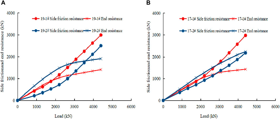
Figure 7. Curves of the calculated pile side friction resistance and the pile end resistance. (A) Test pile of 19# building (B) Test pile of 17# building.
The actual loads applied to the test piles of 19# and 17# buildings are not up to the ultimate value, so there is not an obvious inflection point in the load-settlement curve at the pile top. The load-settlement curves at the pile top in the numerical simulation are subjected to the ultimate load, and the ungrouted 19-1# and 17-1# test piles yield an inflection point under the 4,840 kN, which can be taken as the theoretical ultimate load. The inflection points of 19–2#, 19-3#, 17-2# and 17-3# test piles with post-grouting appear only under the 6,160 kN, and their theoretical ultimate load-bearing capacities increases by 27.3% compared with those of the ungrouted test piles, which indicates that post-grouting at the pile end yield an obvious improvement of the load-bearing capacity of tubular piles. The increase in pile length of the 19-3# and 17-3# test piles compared with the 19-2# and 17-2# test piles has improved their load-bearing capacities to some extent, and the calculated displacements at the pile top under the theoretical ultimate load of the 6,160 kN are slightly smaller.
When the load is small, the calculated pile end displacement and pile top settlement are close to each other, which indicates that the compression of the tubular piles is small due to their large stiffness, and that it is mainly manifested as the overall sinking of the pile. With the increase of load, the difference of the calculated pile end displacement and pile top settlement is also accelerated, indicating that the pile side friction resistance works.
The calculated pile end displacements of grouted 19-2# and 17-2# test piles under the 4,400 kN (3.84 mm and 4.64 mm) are reduced by 56.6% and 53.4% compared with those of ungrouted 19-1# and 17-1# test piles (8.85 mm and 9.87 mm), respectively. The calculated pile end displacements of 19–3# and 17-3# test piles (3.37 mm and 4.36 mm) are reduced by 61.9% and 55.8% compared with those of 19–1# and 17-1# test piles, respectively. This confirms that the application of post-grouting technique to the plastic-hard plastic breccia silty clay can significantly reduce the pile end displacement and thus improve the load-bearing capacity of the tubular piles. The calculated pile end displacements of 19–1# and 19-2# test piles are presented Figure 6.
4.3.2 Analysis of pile end resistance and stress distribution at the pile end
The calculated pile end resistances of the test piles under the loaded conditions are illustrated in Table 4; Figure 7, where the side friction resistance is obtained by subtracting the calculated pile end resistance from the pile top load. When the load is small, the pile end resistance is larger than the pile side friction resistance. Due to the larger stiffness, the compression of the pile itself is small and the pile end resistance accounts for a larger proportion. With the increase of load, the pile side friction resistance gradually works. Due to the accelerated growth rate, a concave growth curve is observed in the figure, while the corresponding increase in pile tip resistance gradually decelerates, so a concave growth curve is observed in the figure. Compared with the ungrouted 19-1# and 17-1# test piles, the proportions of pile end resistance of grouted 19-2# and 17-2# test piles are always larger. As revealed in Table 4, the use of post-grouting technique at pile end for test piles can increase the pile end load-bearing capacity more significantly. Compared with the ungrouted 19-1# and 17-1# test piles, the proportions of pile end resistance of grouted 19-2# and 17-2# test piles are increased by 11.27% and 18.21%, respectively. Post-grouting with plastic-hard plastic breccia silty clay as the bearing stratum can yield excellent grouting effect.
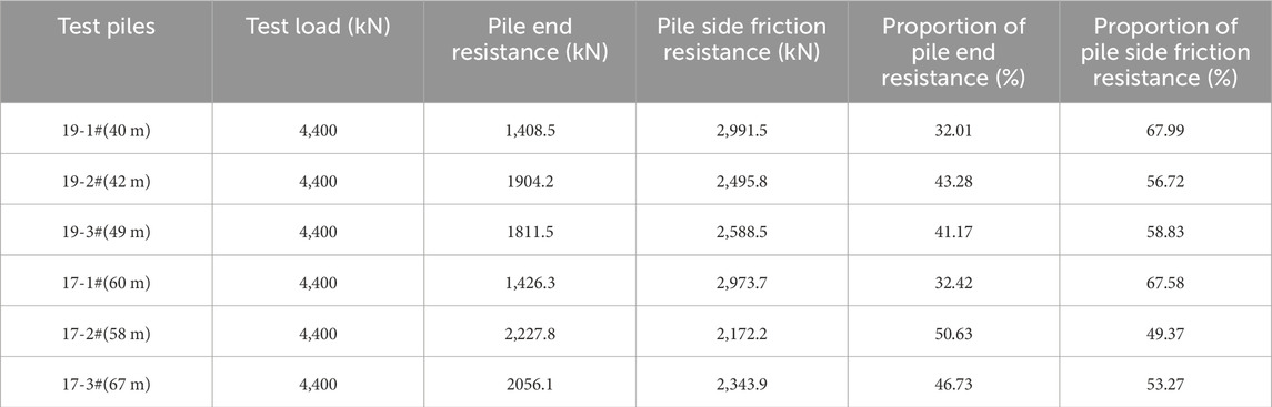
Table 4. Test results of the pile end resistance.
Taking the ungrouted 19-1# and grouted 19-2# test piles and 17-2# test pile as an example, the vertical stress nephograms of the soil in the pile end bearing stratum under the 4,400 kN is presented in Figure 8. It is observed that compared with the ungrouted 19-1# test pile, the vertical stress within the 3-m high grouting bearing stratum zone at the end of grouted 19-2# test pile is larger, and the area with the vertical stress varying from −809 to −834 kn/m2 accounts for a larger proportion. The vertical stresses within the 3-m high grouting zone at the end of 19–1# test pile are mainly concentrated in the range varying from −799 to −828 kN/m2 (red color). The vertical stresses within the 3-m high grouting zone at the end of 17–2# test pile with grouting are mainly distributed in the range varying −1,070 from −1,100 kN/m2. The vertical stress in the bearing stratum of 17–2# test pile is larger than that of 19–2# test pile, which is compatible with the calculation results in Table 4. This is mainly due to the fact that the bead-shaped karst caves are more unfavorable for the side friction resistance of the tubular piles to be exerted, so the pile end resistance is larger.
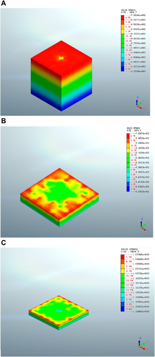
Figure 8. The vertical stress nephograms of the soil in the bearing stratum under the 4,400 kN. (A) 19-1# test pile (B) 19-2# test pile (C) 17-2# test pile.
4.3.3 Analysis of pile side friction resistance
Calculated pile side friction resistance with depth of test piles under the 4,400 kN is illustrated in Figure 9 (load is calculated in three levels in each figure), where the depth of 0–8 m is mainly miscellaneous fill, silty clay, and silty fine sand. For 19-1# and 2# test piles, the depth below 12 m is mainly the bearing stratum of plastic-hard plastic breccia silty clay. For 17-1# and 2# test piles, the depth of 12–54 m is flow-soft plastic breccia silty clay, the depth of 54–57 m is moderately weathered limestone, and the depth below 57 m is the bearing stratum of plastic-hard plastic breccia silty clay.
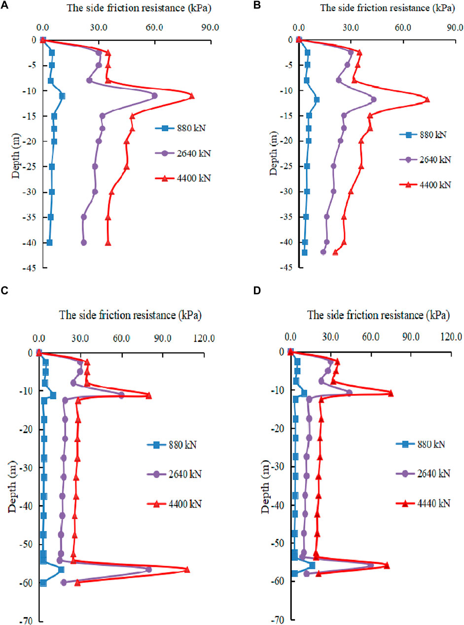
Figure 9. Variation of pile side friction resistance with the depth. (A) 19-1# test pile (B) 19-2# test pile (C) 17-1# test pile (D) 17-2# test pile.
It is observed that as the load applied to the pile top increases, the side friction resistance of the upper soil layer around the pile body is more fully utilized and gradually approaches the final shear stress set at the contact surface. However, the increase in the side friction resistance gradually decreases, while the lower soil layer has a lower exertion rate of side friction resistance than the upper layer. With the increase of load, the side friction resistance can approach the final shear stress set at the contact surface. However, the greater the depth, the greater the deviation of the side friction resistance from the final shear stress. As depicted in the figure, the curve exhibits a sudden change at the location of pebble layer and weathered limestone due to a significant increase in their final shear value compared to that of adjacent soil layers. The upper soil layers around the pile body fail to reach the final specified shear stresses (30 kPa for miscellaneous fill, silty clay, and silty fine sand while 80 kPa for pebbles), indicating that the use of post-grouting at the pile end does not improve the pile side friction resistance. Under the same loading, the side friction resistances of grouted 19-2# and 17-2# test piles decrease significantly compared with those of ungrouted 19-1# and 17-1# test piles, which indicates that the load-bearing capacity at the pile end in the bearing stratum after grouting works progressively during the loading process. The presence of a long segment of flow-soft plastic breccia silty clay (final shear stress is only 30 kPa) in the strata crossed by the 17-1# and 17-2# test piles is the cause for the bead-shaped karst caves restricting the exertion of side friction resistance of the tubular piles.
5 Effectiveness and verification
Pile settlement monitoring is conducted using a precision digital level to investigate the effectiveness of pile end post-grouting technique for the tubular piles. The measurement frequency is one observation every 15 days (adjusted according to the construction progress) during the construction period, one observation every 1 month to 3 months after the completion of the overall structural construction, and one observation every 3 months to 6 months after the building is completed and stabilized. The final observation duration is 2 years. Combined with the actual situation of the site, six observation points are equipped in both 19# and 17# buildings. Settlement observation points are installed by on-site drilling and embedding special settlement nails, which are labelled as 17-1-17–6 and 19-1-19–6, respectively.
The monitored settlement curves of the 19# and 17# buildings are illustrated in Figure 10. It is demonstrated that the buildings do not experience obvious deformation throughout the construction stage and after the completion of construction, and the displacement gradually tends to stabilize. The maximum cumulative settlement of the 19# building is −14.75 mm, with an average settlement of −12.88 mm. The maximum cumulative settlement of the 17# building is −10.01 mm, with an average settlement of −8.98 mm. The cumulative settlement warning value is −20 mm, and there is no abnormality in the settlement observation. The incremental settlement value of each measurement is less than 1 mm, the settlement rate continues to decrease and gradually tends to zero. The settlement of the buildings is within the safe limits.
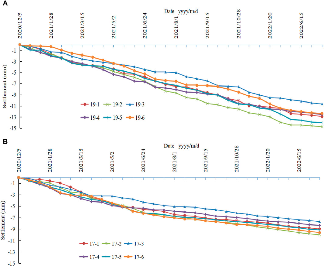
Figure 10. Measured settlement curves. (A) 19# building (B) 17# building.
The above findings indicate that the post-grouting technique adopted in the project significantly reduces the pile end displacement and suppresses the pile top settlement. The post-grouting technique at the end of tubular piles can control the settlement of the building for a long time, thus avoiding abnormal settlement of the building. The settlement observation results indicate that the post-grouting technique adopted in the project is feasible.
6 Conclusion
(1) The pile end load-bearing capacity of prestressed tubular piles in karst region can be significantly increased by adopting post-grouting technique at the pile end. Under the maximum test load, the pile top settlement of grouted test piles can be reduced by 16.8%–22.3% compared with that of ungrouted test piles, and the theoretically simulated ultimate load-bearing capacity can be increased by 27.3%.
(2) Under the maximum test load, the use of post-grouting at the pile end reduces the pile end displacements of tubular piles by 53.4%–56.6% and increases the proportions of pile end resistance by 11.27% and 18.21%, respectively, which indicates the post-grouting with plastic-hard plastic breccia silty clay as the bearing stratum can yield excellent grouting effect.
(3) The bead-shaped karst caves are more unfavorable to the load-bearing capacity of the tubular piles than these filled with plastic-hard plastic breccia silty clay to which the piles have direct access. The presence of a long segment of flow-soft plastic breccia silty clay with a low final shear stress in the strata crossed by the test pile is the cause for the insufficient exertion of side friction resistance of the tubular piles.
(4) The finite element model can effectively simulate the tubular pile-soil interaction. The theoretical analysis of load-bearing behavior of tubular piles in karst region of northern Fujian Province is performed by considering the insufficient exertion of side friction resistance of the prestressed tubular piles and determining the calculation parameters of the pile body, soil body, and grouting reinforcement body.
(5) The average settlements of the test piles of 19# and 17# buildings under karst geological conditions with two different spatial features are −12.88 mm and −8.98 mm, respectively, both of which do not exceed the warning value, indicating that the pile end post-grouting technique adopted in the project is feasible.
(6) The side friction resistance of the upper soil layer around the tubular pile body works earlier than that of the lower soil layer during the loading process. The larger the depth, the greater the deviation of the friction force from the final shear stress. Pile end post-grouting does not increase the side friction resistance. The side friction resistance of grouted test piles is significantly reduced compared with that of ungrouted test piles under the same loading as the pile end load-bearing capacity of the grouted test piles works gradually.
Data availability statement
The original contributions presented in the study are included in the article/Supplementary material, further inquiries can be directed to the corresponding author.
Author contributions
LH: Conceptualization, Data curation, Formal Analysis, Funding acquisition, Investigation, Methodology, Project administration, Resources, Software, Supervision, Validation, Visualization, Writing–original draft. RG: Methodology, Writing–review and editing. JC: Data curation, Writing–review and editing. XY: Formal Analysis, Writing–review and editing.
Funding
The author(s) declare that no financial support was received for the research, authorship, and/or publication of this article. This project is supported by the “Fujian Natural Science Foundation General Project (2021J011122)” and the “Research on the Bearing Characteristics of Bridge Pile Foundations and the Failure Mode of Underlying Karst Cave Roof in North Fujian” funded by the fund.
Conflict of interest
Author JC was employed by Fujian Southeast Design Group Co., Ltd. Author XY was employed by Fujian Jinding Construction Development Co., Ltd.
The remaining authors declare that the research was conducted in the absence of any commercial or financial relationships that could be construed as a potential conflict of interest.
Publisher’s note
All claims expressed in this article are solely those of the authors and do not necessarily represent those of their affiliated organizations, or those of the publisher, the editors and the reviewers. Any product that may be evaluated in this article, or claim that may be made by its manufacturer, is not guaranteed or endorsed by the publisher.
References
Bo, L., Brian, B., Sheil, W., Zhao, P., Qian, B., and Wang, W. (2024). Laboratory testing of settlement propagation induced by pipe-roof pre-support deformation in sandy soils. Tunn. Undergr. Space Technol. 146, 105645. doi:10.1016/j.tust.2024.105645
Boyang, Z., Gang, L., Yingchun, L., and Lin, Z. (2023). Experimental study on the seepage mutation of natural karst collapse pillar (KCP) fillings over mass outflow. Environ. Sci. Pollut. Res. 30 (51), 110995–111007. doi:10.1007/s11356-023-30230-3
Dai, G., Ouyang, H., Gao, L., Guo, Q., and Gong, W. (2023). Experimental study on monotonic and cyclic lateral behavior enhancing mechanism of semi-rigid pile under different foundation reinforced methods in clay. Ocean. Eng. 273 (1), 113955–113961.12. doi:10.1016/j.oceaneng.2023.113955
Dai, L., Pan, Y., Zhang, C., Wang, A., Canbulat, I., Shi, T., et al. (2022). New criterion of critical mining stress index for risk evaluation of roadway rockburst. ROCK Mech. ROCK Eng. 55 (8), 4783–4799. doi:10.1007/s00603-022-02888-7
Ding-Wei, B., Jian-Lin, M. A., and Xing-Guo, L. I. (2018). Experimental study on post grouting of pile foundation of high-speed railway in karst area. Railw. Stand. Des. 62 (06), 83–88. doi:10.13238/j.issn.1004-2954.201706200003
Dong, Y. X., Feng, Z. J., and Hao, Y. M. (2018). Experiment on bearing capacity of bridge pile foundations in karst areas and reasonable rock-socketed depth. J. Traffic Transp. Eng. 18 (6), 27–36. doi:10.19818/j.cnki.1671-1637.2018.06.004
Gong, W., Zhang, Z., Lin, Y., Dai, G., and Huang, H. (2023). Full-scale field test study of bearing characteristics of post-grouting pile for offshore wind turbines. Ocean. Eng. 268 (15), 113451. doi:10.1016/j.oceaneng.2022.113451
Hou, Z., Tang, M., Liang, S., and Zhu, Y. (2021). Optimization of the physical and mechanical properties of grouting material for non-soil-squeezing PHC pipe pile. Crystals 12 (1), 10. doi:10.3390/cryst12010010
Huang, M., Fu, J., and Chen, F. (2019). Shaking table test of seismic dynamic characteristics of karst roof under pile load. Harbin Gongye Daxue Xuebao/Journal Harbin Inst. Technol. 51 (2), 126–135. doi:10.11918/j.issn.0367-6234.201712163
Jinjin, D., Qipeng, C., and Shizhuo, S. (2023). Numerical simulation of vertical bearing capacity of short core PHC pipe piles with cement soil roots. J. Overseas Chin. Univ. Nat. Sci. Ed. 42 (06), 740–747. doi:10.11830/issn.1000-5013.202101034
Kou, H., Li, W., Chu, J., and Yang, D. L. (2020). Model tests on open-ended concrete pipe piles jacked in sand. Mar. Georesources Geotechnol. 38 (7), 939–946. doi:10.1080/1064119x.2019.1642972
Li, X., Dai, G., Zhu, M., and Gong, W. (2019). Application of static loading tests to steel pipe piles with large diameters in Chinese offshore wind farms. Ocean. Eng. 186 (15), 106041. doi:10.1016/j.oceaneng.2019.05.023
Lianpeng, D., Yishan, P., and Aiwen, W. (2018). Study of the energy absorption performance of an axial splitting component for anchor bolts under static loading. Tunn. Undergr. Space Technol. 81, 176–186. doi:10.1016/j.tust.2018.07.009
Lianpeng, D., Yishan, P., Zhonghua, L., Aiwen, W., Yonghui, X., Feiyu, L., et al. (2021). Quantitative mechanism of roadway rockbursts in deep extra-thick coal seams: theory and case histories. Tunn. Undergr. Space Technol. 111 (May), 103861.1–103861.14. doi:10.1016/j.tust.2021.103861
Paik, K., and Salgado, R. (2004). Effect of pile installation method on pipe pile behavior in sands. Geotechnical Test. J. 27 (1), 1–11. doi:10.1520/gtj11391
Qi, W., Yuncai, W., Bei, J., Zhenhua, J., and Haojie, X. (2023). Geomechanics model test research on large deformation control mechanism of roadway disturbed by strong dynamic pressure. Geohazard Mech. 1 (2), 140–152. doi:10.1016/j.ghm.2023.06.002
Sheng-Hua, X., Zheng-Wu, L., Yong-Feng, D., Bian, X., Zhu, H. H., Zhou, F., et al. (2022). Bearing performance of steel pipe pile in multilayered marine soil using fiber optic technique: a case study. Mar. Georesources Geotechnol. 40 (11), 1453–1469. doi:10.1080/1064119x.2021.2005192
Shimeng, W., and Xinsheng, Y. (2020). Study on seismic performance of C105 prestressed high strength concrete hollow pipe pile. Mater. Sci. Forum 980, 282–290. doi:10.4028/www.scientific.net/msf.980.282
Tao, J., Jin, R., and Lu, F. (2017). Field testing of rigid pile composite foundation for high-rise buildings in karst area. Jianzhu Jiegou Xuebao/Journal Build. Struct. 38 (6), 163–174. doi:10.14006/j.jzjgxb.2017.06.018
Wang, P., Ding, H., and Zhang, P. (2020b). Influence of karst caves at pile side on the bearing capacity of super-long pile foundation. Math. Problems Eng. 2020 (2), 1–13. doi:10.1155/2020/4895735
Wang, Z. M. G., Ni, P., Chen, Z., and Mei, G. (2020a). Consolidation solution of soil around a permeable pipe pile. Mar. Georesources Geotechnol. 38 (9a10), 1097–1105. doi:10.1080/1064119x.2019.1655119
Wei, W., Qingke, N., and Wei, Y. (2017). Research on the effect of roof failure to the load-bearing characteristics of single pile penetrating karst cave. Tumu Gongcheng Xuebao/China Civ. Eng. J. 50 (S1), 88–93. doi:10.15951/j.tmgcxb.2017.s1.016
Wen, L., Kong, G., Li, Q., and Zhang, Z. (2020). Field tests on axial behavior of grouted steel pipe micropiles in marine soft clay. Int. J. Geomechanics 20 (6), 06020006. doi:10.1061/(asce)gm.1943-5622.0001656
Xiang, L., Ji, Y., and Jiaqi, W. (2019). Optimization practice of pile foundation for high-rise buildings in deep karst areas. Karst China 38 (04), 591–599. doi:10.11932/karst20190418
Xiucheng, L., Jie, X. U., and Xinpeng, Y. (2019). Study on bearing behavior of large diameter driven steel pipe pile in coral reef geology. Ocean Eng. 37 (06), 157–163. doi:10.16483/j.issn.1005-9865.2019.06.017
Xuefeng, C. (2019). Application of high pressure grouting in reinforcement treatment of pile end bearing layer. Constr. Technol. 48 (S1), 216–218.
Yan, Z., Deng, L. F., and Zhang, H. Q. (2022). Vertical field behavior of a deep large-diameter driven pipe pile in multilayered soils. Ocean. Eng. 247 (Mar.1), 110782–110782.13. doi:10.1016/j.oceaneng.2022.110782
Keywords: karst region of northern Fujian Province, prestressed tubular pile, post-grouting, load-bearing behaviors, breccia silty clay
Citation: Huang L, Gao R, Chi J and Yan X (2024) Study on load-bearing behaviors of prestressed post-grouting tubular piles in the karst region of northern Fujian Province, China. Front. Earth Sci. 12:1387028. doi: 10.3389/feart.2024.1387028
Received: 16 February 2024; Accepted: 25 March 2024;
Published: 09 April 2024.
Edited by:
Pengjiao Jia, Soochow University, ChinaCopyright © 2024 Huang, Gao, Chi and Yan. This is an open-access article distributed under the terms of the Creative Commons Attribution License (CC BY). The use, distribution or reproduction in other forums is permitted, provided the original author(s) and the copyright owner(s) are credited and that the original publication in this journal is cited, in accordance with accepted academic practice. No use, distribution or reproduction is permitted which does not comply with these terms.
*Correspondence: Lingjun Huang, MTIwNTY1MTY1QHFxLmNvbQ==