 Kristina Navickaitė
 Christian Bahl
 Kurt Engelbrecht
- Department of Energy Conversion and Storage, Technical University of Denmark, Roskilde, Denmark
A novel flow structure of a solid active magnetic regenerator is proposed in this paper. The numerical performances of two nature-inspired flow geometries, based on double corrugated tubes with an elliptical cross-section, are compared to the performance of conventional flow structures for Active Magnetic Regeneration (AMR) applications, namely, packed spheres and a cylindrical micro-channel matrix. The numerical performance of all the geometries is analyzed in terms of cooling power and coefficient of performance. Regenerators with various porosities and two different hydraulic diameters of the flow channels are evaluated varying utilization at fixed temperature spans between the hot and cold reservoirs. The selection of the regenerator geometry is based on two actual AMR machines. The numerical results demonstrate that a suitably optimized AMR geometry with a double corrugated flow pattern provides the same or higher efficiency at higher porosity compared to conventional AMR flow geometries. These findings suggest that the magnetocaloric material used to construct AMR beds can be exploited more efficiently and at a lower investment cost of an AMR device when suitable double corrugated flow pattern is used.
Introduction
Heat pump technology is widely used in residential and industrial applications. Heat pumps are especially popular choices for heating, ventilation, and air conditioning (HVAC) applications. In the USA HVAC applications constitutes more than 40% of the whole primary energy consumptions (Goetzler et al., 2014). Currently, practically all heat pumps use the vapor compression cycle utilizing synthetic refrigerants that contribute to global greenhouse gas emission related to leakage to the ambient. A step toward prohibition of using these synthetic refrigerants has been already made (European Commission, 2013). This implies that new less harmful substances must be developed to be used in vapor compression cycle.
On the other hand, alternative cooling technologies have gained more interest from the scientific and industrial perspectives. A few examples of such technologies are heat pumps driven by the elasto- or magnetocaloric effect (MCE). Both of these technologies utilize solid refrigerants and water based heat transfer fluids with some anticorrosion inhibitor, thus can be more environmentally friendly. Moreover, the U. S. Department of Energy (DOE) listed these technologies in the first and fourth places, respectively, as the most promising alternatives to vapor compression cycle (Goetzler et al., 2014) from an energy savings standpoint. Although elastocalorics was chosen as the most promising non-vapor compression technology, it is still at the very beginning of development (Goetzler et al., 2014; Engelbrecht, 2019). On the other hand, magnetocaloric technology, which is the focus of this article, is a more mature technology (Goetzler et al., 2014; Zimm et al., 2018). It has attracted a great deal of attention from the scientific community as well as industrial interest since the first MCE-based heat pump was demonstrated in 1975 (Brown, 1976, 1981). Nevertheless, this novel cooling approach still must meet a number of challenges before it can be widely adopted commercially.
First, magnetic cooling devices should provide the same or higher efficiency than conventional vapor compression machines at an equivalent cooling power and temperature span. In addition, magnetocaloric materials (MCM) that are currently available exhibit severe drawbacks, such as hysteresis (for strongly first order phase transition (FOPT) materials), narrow working temperature range (for FOPT materials), brittleness and mechanical instability (Lyubina, 2017). Solutions have been found for some of these challenges. For instance, hysteresis in FOPT materials has been reduced to a negligible value, ΔThyst = 0.4 K and μ0Hhyst = 0.1 T for porous LaFe11.6Si1.4. Lowering hysteresis in FOPT materials weakens their transition, bringing it almost to second order phase transition (SOPT), however, a significant MCE can still be obtained (Provenzano et al., 2004; Lyubina, 2017). Note that MCMs are characterized according to their magnetic phase transition, which can be continuous (second order) or discontinuous (first order) when approaching Curie temperature, TC (Smith et al., 2012). It must be pointed out that development and characterization of MCMs is time-consuming process. Recently a novel approach to characterization of MCMs that significantly reduces the required efforts and time for evaluating newly developed MCMs was presented in Maiorino et al. (2019).
Aside from the material issues, there are a number of engineering problems that must be solved as well. In each developed MCE prototype, a small fraction of engineering problems, such as arrangement of magnetic circuit (Arnold et al., 2014), increase of cycle frequency (Velázquez et al., 2014, 2016) and fluid flow arrangement (Eriksen et al., 2015; Dall'Olio et al., 2017) are addressed. Extensive reviews of the developed machines are given in Kitanovski et al. (2015) and Balli et al. (2017). Recently it was demonstrated numerically and experimentally that maldistribution of heat transfer fluid through regenerator beds leads to severe reduction of the machine performance (Eriksen et al., 2016; Nakashima et al., 2018; Trevizoli et al., 2018).
Another machine performance limiting issue is the geometry of flow channels of porous AMR. It is desirable to have a high heat transfer and low pressure drop so that high cooling power with a high coefficient of performance (COP) could be obtained. However, a fine AMR geometry provides high cooling power, but can result in low efficiency due high pressure drop and therefore pump work (Kitanovski et al., 2015). A great deal of research efforts has been devoted to experimental and numerical investigations of various geometries of AMR beds seeking to map out the optimized parameters such as particle size, length and an aspect ratio of a packed bed in order to improve performance of a magnetocaloric heat pump (Tušek et al., 2011, 2013b; Moore et al., 2013; Lei et al., 2017; Trevizoli et al., 2017). Due to relatively simple manufacturing, the most widely reported experimentally tested AMR geometries are packed beds with spherical or irregular shaped particles and parallel plates (Engelbrecht et al., 2013; Tušek et al., 2013a,b; Jacobs et al., 2014; Aprea et al., 2016; Lei, 2016; Bahl et al., 2017; Lei et al., 2018; Navickaite et al., 2018a,b).
It was demonstrated by numerous experimental and numerical work that the efficiency of a magnetocaloric device can be improved by optimizing the geometry of regenerator beds (Li et al., 2012, 2014; Moore et al., 2013; Tušek et al., 2013a; Eriksen et al., 2015; Lei et al., 2017; Trevizoli et al., 2017). A comprehensive numerical study on various AMR geometries was presented in Lei et al. (2017). There, circular and rectangular micro-channels, packed screens along with packed sphere beds and parallel plates were investigated. The numerical results demonstrated that the AMR with packed screens could provide a COP of 7.7, which is higher than that of an AMR with packed spherical particles at the same operational conditions. Nevertheless, manufacturing of the woven screens is too complicated considering currently available MCMs (Lei et al., 2017). Performance of the regenerators with square pins (Trevizoli et al., 2017) and packed cylinders (Tušek et al., 2013b) was experimentally compared to that of AMR with packed spherical particles and parallel plates. The AMRs with packed spherical particles, reported in Tušek et al. (2013b) and Trevizoli et al. (2017), outperformed other geometries in terms of COP and obtained cooling power.
The possibility to manufacture regenerators using selective laser melting (Moore et al., 2013; Trevizoli et al., 2019) or laser beam melting (Wieland et al., 2018) opens an opportunity to investigate different geometries, such as fin-shaped rods or wavy channels, in line stacked and staggered fibers. It was proven that the regenerators, fabricated with selective laser melting, do not show degradation of MCE during 106 cycles of a changing magnetic field (Moore et al., 2013). However, quenching after annealing causes internal strains (Moore et al., 2013), which lead to propagation of cracks in the regenerators.
Because a successful AMR geometry should provide high heat transfer at a low cost in pressure drop, a double corrugated geometry is proposed as a porous AMR structure. Recently reported additive manufacturing techniques could enable this novel regenerator geometry so a modeling study of this geometry is timely. Recent experimental results on double corrugated tubes, on which the flow geometry is based, found that the double corrugated tubes demonstrate up to 160% higher overall heat transfer efficiency at constant pumping power compared to an equivalent straight tube (Navickaite et al., 2019b,c). This means that increases in heat transfer in double corrugated tubes are more significant than increases in pressure drop. Therefore, the double corrugated geometry, used as a flow pattern of a porous structure of an AMR, has the potential to outperform AMRs with conventional flow structures.
In this study, a numerical model is used to predict the performance of an AMR using a regenerator comprised of double corrugated flow passages. The double corrugated geometry is compared to two conventional flow structures of AMR, packed spherical particles and a cylindrical micro-channel matrix. In this study, the volume of the regenerators was held constant. All the modeled regenerators were evaluated comparing the same porosity, ε, and hydraulic diameter, Dh, of the flow channels. This implies that the interstitial area, as, for the compared regenerators was identical. Note that several cases of varying porosity ε as well as hydraulic diameter Dh were modeled and compared independently.
AMR Geometries
The performance of a regenerator strongly depends on its shape. For example, in general, wide and short regenerators favor packed sphere beds with sufficiently fine particles rather than stacked plates or other types of structured flow channels. This is because a packed sphere bed can provide significantly higher Qcool than a regenerator with parallel plates while the pressure drop does not significantly reduce COP. On the other hand, in general, long and narrow regenerators perform better when the flow channels have an ordered structure, e.g., stacked parallel plates or a cylindrical micro-channel matrix. This is because the increase in pressure drop with packed spherical particles in this kind of regenerators is too high to establish an operationally useful COP (Tušek et al., 2013a,b; Lei et al., 2017; Trevizoli and Barbosa, 2017).
Thus, two different types of the regenerator cassettes were selected for the numerical analysis presented in this article. The size of the first type of the regenerators is based on the cassettes of the MagQueen, which is a magnetocaloric heat pump, developed at DTU Energy (Dall'Olio et al., 2017; Johra et al., 2018). Originally, the cassettes of MagQueen were tapered in order to obtain higher COP. In this study, tapering of the cassettes is neglected. These cassettes are referred as “cassette 1.” This geometry was selected because it is a good example of short and wide regenerators.
Cassettes of a AMR at KTH Royal Institute of Technology, Stockholm, Sweden (Monfared, 2018a,b) are a good example of narrow and long regenerators. These cassettes are referred as “cassette 2”. It must be noted that cassette 2 was scaled up by a factor of 2 to make the volumes of cassette 1 and cassette 2 equal. The dimensions of the modeled regenerators are summarized in Table 1, where it is seen that cassette 1 is less than half of the length of cassette 2 and has 2.4 times larger cross-section area. This is visualized in Figure 1. Note that the mass of the MCM filled in the cassettes depends on the decided porosity ε of the regenerator.
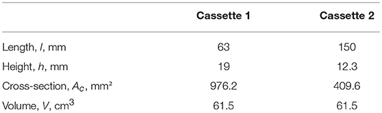
Table 1. Geometric characteristics of the modeled cassettes.
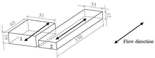
Figure 1. Sketch of the modeled AMR beds. 1—cassette of the MagQueen, 2—cassette of the magnetocaloric prototype at KTH Royal Institute of Technology, Stockholm, Sweden.
Because a porous media AMR model is used, the geometries must be characterized by suitable correlations, describing physical phenomena of heat transfer in fluid in terms of Nusselt number Nu (Equations 11, 12) and pressure drop in terms of friction factor f . Three regenerator geometries are modeled in this study: packed spherical particles, cylindrical micro-channel matrix and double corrugated channels. The regenerators with spherical particles are fabricated by randomly packing small spherical particles into a regenerator housing. It is assumed that the porosity ε of the randomly packed spherical particles is constant at 0.36. Moreover, for modeling purposes, it is assumed that all spheres are of the same size. Therefore, the particle size Dsp is sufficient to characterize the packed sphere bed.
It must be mentioned that the single value of hydraulic diameter Dh = 0.13 mm of the AMR with spherical particles was considered for numerical simulations, while two values of Dh for the AMR with cylindrical micro-channel matrix and double corrugated flow patterns were analyzed. This is because the hydraulic diameter of the flow channels in AMR with packed spherical particles is proportional to Dsp, as it is seen from Equation (1) (Lei et al., 2017). This means that in order to vary the hydraulic diameter of flow channels of the AMR with spherical particles, it is necessary to change the size of the particles. It is well-known that the performance of the AMR with packed spherical particles strongly depends on particle size.
Where Dh is hydraulic diameter, Dsp is sphere diameter, ε is porosity.
The differential volume of the geometry of the AMR with packed spherical particles is presented in Figure 2. The regenerator porosity ε = 0.36 and particle size Dsp = 0.35 mm result in hydraulic diameter of the flow channels Dh = 0.13 mm.
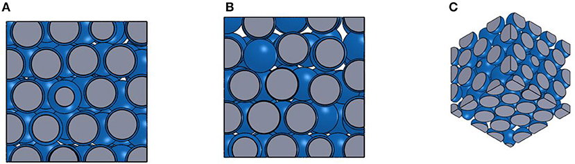
Figure 2. (A) A differential volume of the zoomed-in top/bottom view of the AMR with packed spherical particles. (B) A differential volume of a zoomed-in side view of AMR with packed spherical particles. (C) A differential volume of a zoomed-in isometric view of AMR with packed spherical particles. The solid material is displayed in gray and flow channels are displayed in blue.
Since a 1D model is implemented, the performance of the regenerator is modeled using correlations describing heat transfer between the MCM and heat transfer fluid and friction factor. The heat transfer in the AMR with packed spherical particles is expressed using Nusselt number Nu, given by Equation (2) (Wakao and Kaguei, 1982).
Where Re is the Reynolds number, Pr is the Prandtl number, χ is correction factor of internal temperature gradient (Engelbrecht et al., 2006), Bi is Biot number.
The Ergun equation (Ergun and Orning, 1949) for pressure drop was modified to express the friction factor f in the AMR with packed spherical particles. The friction factor is given in Equation (3).
The AMR with cylindrical micro-channel matrix can be constructed using additive or micromanufacturing techniques. The porosity ε of such regenerator can be controlled by adjusting the wall thickness between the flow channels and changing the diameter of the flow channels. The differential volume of the geometry of the AMR with cylindrical micro-channel matrix is presented in Figure 3, where the regenerator porosity is ε = 0.54 and hydraulic diameter of the flow channels Dh = 0.35 mm.
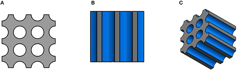
Figure 3. (A) A differential volume of the zoomed-in top/bottom view of the AMR with the cylindrical micro-channel matrix. (B) A differential volume of a zoomed-in side view of AMR with the cylindrical micro-channel matrix. (C) A differential volume of a zoomed-in isometric view of AMR with the cylindrical micro-channel matrix. The solid material is displayed gray and the flow channels are displayed in blue.
The heat transfer between solid and fluid for the AMR with a cylindrical micro-channel matrix is obtained using the classical Hausen correlation as reported in Lei et al. (2017), which is given in Equation (4).
Where l is the length of the regenerator. The friction factor is calculated from Equation (5) (Munson et al., 2002).
Since the hydraulic diameter of the flow channels of AMRs are generally very small, typically less than a millimeter, the fluid flow is always laminar, thus the correlations, given in Equations (4) and (5), are the most suitable for calculating heat transfer and friction factor in AMRs with circular micro-channels.
The double corrugated tubes, which are the base geometry of the AMR with the double corrugated flow patterns, are fully described in Navickaite et al. (2019a,b,c). The geometry of double corrugated tubes is inspired by the capability of several fish species to maintain their full or regional body temperature above that of surrounding water through the use of a vascular counter flow heat exchanger that recovers heat generated in the muscles (Dickson and Graham, 2004; Wegner et al., 2015). This is due to a fascinating arrangement and shape of the blood vessels of these fishes. It was found that at an orthogonal to the blood flow direction there are numerous of tightly bundled blood vessels with elliptical-like cross-sections having various aspect ratios (Wegner et al., 2015). Two-dimensional corrugation of the blood vessels intensifies heat transfer in a fish body by preventing the development of the thermal boundary layers. At the same time, the increase in pressure drop is limited in order to avoid stress on the heart. In order to mimic this shape two sets of equations, describing the surface of double corrugated tubes, were derived. Equation (6) describes the double corrugated tubes with a constant hydraulic diameter Dh and (Equation 7) describes the double corrugated tubes with a constant cross-section area Ac. As an example, Figure 4 presents a single double corrugated tube generated using Equation (6).
Where R is radius of an equivalent straight tube, AR is aspect ratio of x and y axes, z is the longitudinal position, and K is the corrugation period.
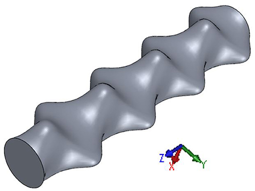
Figure 4. Isometric view of a double corrugated tube generated in CAD software using Equation (6).
The impact of the corrugation period K and aspect ratio AR on the thermo-hydraulic performance of the double corrugated tubes has been analyzed using CFD software. The modeling results have been reported in Navickaite et al. (2019a), and in that article it was demonstrated that in the low Reynolds number region the double corrugated tubes with shorter corrugation period K are more effective (Navickaite et al., 2019a). Moreover, increasing thermal efficiency was obtained for double corrugated tubes with increasing AR up to 2.2. The CFD analysis was carried out in the laminar flow regime at constant wall temperature conditions. Moreover, the simulations were performed using constant pressure drop conditions that were normalized to the length of modeled tubes. This implies that the mass flow rate passing through the tubes varied (Navickaite et al., 2019a).
The double corrugated tubes that demonstrated the most promising numerical results were fabricated using selective laser melting technique and experimentally characterized in a tube-in-shell heat exchanger. Experimental results revealed that double corrugated tubes with longer periods K demonstrate lower increase in thermal efficiency when considering the same aspect ratio AR. However, the increase in friction factor is also lower for these tubes. On the other hand, double corrugated tubes with higher AR demonstrated significantly higher thermal efficiency compared to ones with lower AR considering same K value. However, with increasing Re, tubes with intermediate AR values outperformed ones with high AR (Navickaite et al., 2019b,c).
The double corrugated tubes proved experimentally to be more efficient than an equivalent straight tube at constant pumping power for a standard heat transfer application by calculating performance evaluation criteria PEC (Navickaite et al., 2019b,c). PEC is a tool for evaluating effectiveness of an enhanced geometry used for passive heat transfer augmentation and is given in Equation (8).
Where Nu and f are Nusselt number and friction factor for a double corrugated tubes, respectively, and Nu0 and f 0 is the Nusselt number and friction factor for a straight tube, respectively.
Experimentally investigated double corrugated tubes demonstrated up to 160% increase in PEC in the Re region from 1,000 to 2,500 (Navickaite et al., 2019b,c). This means that increases of the heat transfer in double corrugated tubes is higher than the penalty for increased pressure drop. This is a desired characteristic of a successful AMR geometry, although it should be stressed that PEC was not derived for AMR applications. Another measure of the heat transfer to pressure drop in a regenerator is the ratio of Nu to f , and the cylindrical channels exhibit a higher ratio than the corrugated channels as shown in Figure 6C. A micro-channel matrix along with two selected double corrugated flow patterns was implemented in a 1D AMR model adopting suitable coefficients for increase in Nusselt number and friction factor that are given in Table 2. The correlations for calculating Nu and f for double corrugated tubes reported in Navickaite et al. (2019b,c) are valid in the range of Reynolds number, Re, from 1,000 to 2,500. The range of Re in this AMR modeling was from 1 to 300. Thus, the obtained Nu correlations for double corrugated tubes cannot be directly implemented in the 1D AMR model. Therefore, ratios of Nu and friction factor, f , were obtained between double corrugated tubes and the reference straight tube in the laminar flow regime (1,000 ≤ Re ≤ 2,000) (Navickaite et al., 2019b,c). They were implemented as scaling factors for Nu and f, assuming that the double corrugated tubes would demonstrate similar performance ratios in the lower Re region as in the region in which they were experimentally investigated. Nu and f for the AMRs with double corrugated flow patterns were determined by scaling the straight tube correlations, and the scaling factors are given in Table 2. The scaling factors for Nusselt number and friction factor are given in Equations (9) and (10).
From Table 2, one can see that the double corrugated tubes, selected as the flow patterns of porous structure of a solid AMR, demonstrate rather different performance. The double corrugated tube with constant Dh demonstrates the highest PEC that was tested (Navickaite et al., 2019c). On the other hand, the double corrugated tube with constant Ac shows one of the lowest PECs that was tested (Navickaite et al., 2019b). However, the ratio between increase in f and increase in Nu is much smaller in the double corrugated tube with constant Ac than with constant Dh, demonstrating values of 35 and 52%, respectively. Therefore, these two double corrugated tubes were selected for the numerical analysis.
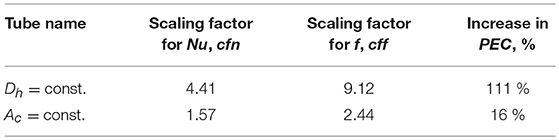
Table 2. Scaling factors for Nu and f for double corrugated tubes compared to the equivalent straight tube and increase in PEC in region of Re from 1,000 to 2,000.
The porosity of the AMR with the double corrugated flow patterns can be controlled similarly as of the AMR with the cylindrical micro-channel matrix, by controlling the size of the flow channels and wall thickness between them. The differential volume of the geometry of the AMR with the double corrugated flow pattern is presented in Figure 5, where porosity is 0.54 and hydraulic diameter of the flow channels is 0.35 mm. In Figure 5, it can be seen that the double corrugated channels are arranged in a rectangular array and stacked in a way that the peak of one channel is at the same level of the narrowest part of the neighboring channels. In this way, compactness of the AMR is increased with the possibility to obtain porosity as high as 0.54.
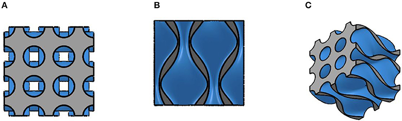
Figure 5. (A) A differential volume of the zoomed-in top/bottom view of the AMR with the double corrugated flow pattern. (B) A differential volume of a zoomed-in side view of AMR with the double corrugated flow pattern. (C) A differential volume of a zoomed-in isometric view of AMR with the double corrugated flow pattern. The solid material is displayed by gray color and flow channels are displayed by blue color. The video with animated rotation of the differential volume is available at Supplementary Video 1.
Fabrication of the AMR with the double corrugated flow patterns is possible using additive manufacturing techniques, such as laser melting. It was demonstrated that it is possible to manufacture a regenerator with straight flow channels that have a hydraulic diameter Dh = 0.3 mm (Wieland et al., 2018). However, the double corrugated flow structures could introduce additional complexity in fabricating flow channels using the laser melting process. Therefore, a slightly larger hydraulic diameter of flow channels was selected for the numerical analysis of the regenerators with ordered flow structures.
A conventional comparison between the heat transfer and pressure drop performances of each regenerator is shown in Figure 6. Note that the correlations were compared at identical conditions, i.e. same fluid properties, same length of regenerators (applicable to AMR with ordered flow structures), same hydraulic diameter of the flow channels and same porosity of regenerators.
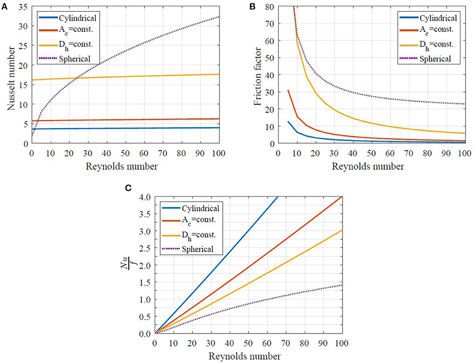
Figure 6. (A) Nusselt number as a function of Reynolds number for all geometries modeled. (B) Friction factor as a function of Reynolds number. (C) Ratio of Nusselt number to friction factor as a function of Reynolds number for different geometries with porosity ε = 0.36, hydraulic diameter Dh = 0.13 mm, regenerator length with ordered flow structures l = 63 mm.
In Figure 6A, one can see that the highest Nusselt number is exhibited by the AMR with packed spherical particles for Re > 20. On the other hand, the AMR with double corrugated flow patterns, especially the one with constant Dh, provide significantly greater Nu than the AMR with the cylindrical micro-channel matrix. Nevertheless, the latter geometries have a significantly greater friction factor.
Since a successful AMR geometry should provide high heat transfer and low pressure drop, the correlations presented above are compared using the linear ratio between Nusselt number and friction factor, as shown in Figure 6C. It is clear that the AMR with the cylindrical micro-channel matrix demonstrates the best ratio between Nusselt number and friction factor, while the AMR with packed spherical particles demonstrates the lowest ratio. Thus, the AMR with the cylindrical micro-channel matrix with small hydraulic diameter of flow channels is potentially more efficient than the AMR with packed spherical particles.
It is worth mentioning that there is a major difference between PEC values at constant pumping power and the linear ratio between Nusselt number and friction factor for the corrugated channels. In the previous case, the performance of an enhanced geometry is evaluated representing constraints on certain operational conditions, namely the available pumping power. On the other hand, the linear ratio of Nusselt number to friction factor provides performance evaluation at constant mass flow rate. In this case, the enhanced geometry is required to provide higher thermal effectiveness compared to a conventional geometry and it is allowed to operate at higher pressure drop (Webb and Kim, 1994). Thus, the later method does not provide specific operational conditions as opposed to the PEC method. When modeling performance of AMRs, the goodness of the geometry in question is evaluated in terms of COP and cooling power.
One-Dimensional AMR Model
Many different approaches have been reported in literature to model AMRs. A review on numerical AMR models that were developed by 2011, with a focus on various components of AMR models emphasizing their effect on modeling results, is given in Nielsen et al. (2011). The vast majority of the developed AMR models are one-dimensional (Tušek et al., 2011; Aprea et al., 2012), although, two- and three-dimensional models have been presented as well (Bouchard et al., 2009; Liu and Yu, 2011; Aprea et al., 2015). Two-dimensional models are often used to model AMRs with ordered structures, i.e., parallel plates, cylindrical or square channels (Tušek et al., 2013a) due to differences in the definition of heat transfer between fluid and a solid.
Regardless of the modeling approach, all AMR models must calculate heat transfer in the solid MCM matrix, and the MCE due to varying magnetic field, coupled with convective heat transfer in the fluid. Thus, the governing equations, as described first in Lei (2016), are given in Equations (11) and (12).
Where k is thermal conductivity, T is temperature, ρ is density, cf is specific heat of a heat transfer fluid, cH is specific heat capacity of MCM at constant magnetic field, s is specific entropy, Ac is cross-sectional area, as is specific area, and ε is porosity, x is axial positon, t is time, ṁ is mass flow rate, H is internal magnetic field, Nu is Nusselt number and is pressure drop per unit length. The subscripts f, s, disp and stat represents fluid, solid refrigerant, dispersion and static, respectively.
The full model description, applied modifications and the discretization of governing equations are given in Lei (2016). The first term on the left hand side of Equation (11) describes thermal conduction through the AMR bed; the second term represents the heat transfer between the fluid and MCM. The energy storage and magnetic work of the MCM are defined by the term on the right hand side. The first term on the left hand side of Equation (12) is thermal conduction through the fluid, the second term is the enthalpy flow, the third term is the heat transfer between the fluid and MCM, and thus it couples both energy equations. Then the viscous dissipation is the fourth term on the left hand side of Equation (12) and the energy storage in the fluid is the term on the right hand side.
The 1D AMR governing equations were developed using the following assumptions:
1. The MCM is uniformly distributed in the AMR bed;
2. There is no flow leakage or bypass;
3. The MCM exhibits uniform magnetization and demagnetization;
4. Fluid enters the AMR at uniform bulk temperature and uniform velocity profile across the cross-section of an AMR;
5. The fluid is incompressible;
6. No phase change occurs in the fluid;
7. The radiation heat transfer is negligible.
The number of space nodes used in this study was 40. It was found that the accuracy of the numerical solution did not increase by increasing spatial nodes by 25 and 50%. The model was considered to reach convergence when the numerical tolerance of 1·10−5 was attained and the number of iterations exceeded 500. The 1D AMR model used in this study has been previously validated against SOPT and FOPT materials as well as multi-layered materials (Lei et al., 2018; Navickaite et al., 2018b).
As each geometry and hydraulic diameter can have its own set of operating parameters and overall regenerator shape that give the best performance, it is important to model a range of operating conditions while holding parameters such as material properties and total regenerator volume constant. For all modeled cases, the regenerator volume, MCM, magnetic field profile, cycle frequencies considered, and operating temperatures were held constant. Since packed sphere beds are assumed to have a constant porosity that cannot vary, all geometries were compared for a porosity of 0.36 and a hydraulic diameter of 0.13 mm. All other geometries were also modeled for porosities of 0.27, 0.45, and 0.54 and for hydraulic diameters of both 0.13 and 0.35 mm. The hydraulic diameter value of 0.35 mm was chosen to reflect current technological limitations of additive manufacturing techniques (Wieland et al., 2018) and 0.13 mm corresponds to a packed sphere regenerator with 0.35 mm diameter spheres. The porosity of 0.54 is considered the maximum possible porosity of this type of packed double corrugated tubes. When the porosity was varied, the mass of MCM varied correspondingly. The input data for the 1D AMR model are summarized in Table 3.
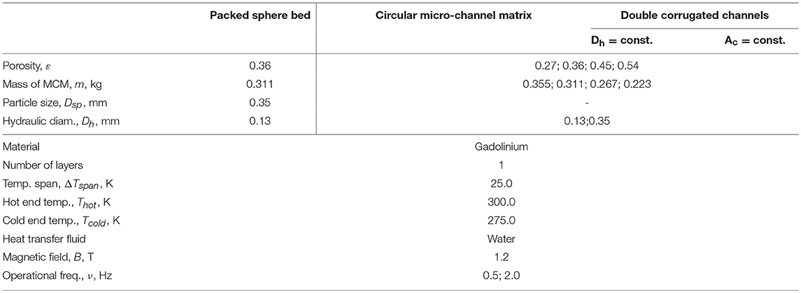
Table 3. Material properties and boundary conditions for the 1D AMR model.
As can be seen in Table 3, the numerical analysis was carried out for a single-layer AMR using the benchmark MCM gadolinium (Gd). Since Gd is the most widely reported material used for AMR modeling and verifying performance of different devices, it was selected for this study. Note, that the aim of this article is to discuss which type of flow pattern is better to use for constructing an AMR that would allow obtaining the best performance, rather than which material should be used in MCE driven devices or how many layers regenerators must consist of.
The performance of all the analyzed geometries was grouped according to AMR characteristics, i.e., porosity, ε, and hydraulic diameter, Dh. Thus, mass, m, of the MCM and the specific heat transfer surface, as, are the same for all the compared geometries in a single chart. Therefore, the difference in performance is due only to the different geometries.
The performance of the numerically analyzed geometries was evaluated varying utilization, U, which is defined in Equation (13) and at the fixed temperature span of ΔTspan = 25 K. The modeled frequencies were 0.5 and 2 Hz, as shown in Table 3.
Where mf is mass of the heat transfer fluid pushed through the regenerator during one blow, ms is mass of MCM, cH is specific heat of MCM. An average value of cH, obtained during simulations is used to calculate utilization for all modeled cases, since cH is temperature and magnetic field dependent.
Results and Discussion
Before analyzing the numerical results in details, it must be noted that two solutions of cooling COP can often be obtained for the same value of Qcool (except the maximum Qcool, where a single cooling COP exists) as it is seen from Figures 8–11.
This is because Qcool established by an AMR regenerator increases with increasing the flow rate of the heat transfer fluid as it is seen from Figure 7 (left axis). However, when the flow rate becomes too large, the regenerator cannot establish sufficient temperature span and the cooling power is reduced (Kitanovski et al., 2015). On the other hand, the highest COP can be obtained at low flow rates. As the flow rate increases above the maximum COP value, the COP decreases due to higher pressure drop and increased heat transfer losses, as can be seen in Figure 7 (right axis). Combining results for Qcool and COP, one can see from Figure 7 (left axis), that cooling power of 40 W can be obtained at two different utilization values U of 0.27 and 0.65. In Figure 7 (right axis), can be seen that there are two COP values of 5.5 and 2.0 for these specific utilization values, respectively. Therefore, the presentation of numerical results in a form where cooling COP is a function of Qcool, as presented in Figures 8–11, provides a clearer understanding of the performance of the investigated regenerators at given conditions. It is important to keep in mind that most cooling applications will require a specific cooling power and the best geometry therefore has the highest COP at the desired cooling power. In the presented figures, the geometry that gives the highest COP at any Qcool can be readily determined. The variation in the system performance is given by variation in the utilization, which is not plotted.
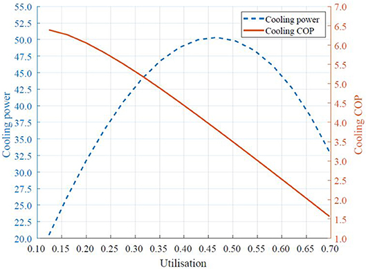
Figure 7. Cooling power (left axis) and cooling COP (right axis) as a function of utilization in cassette 1 with the cylindrical micro-channel matrix at ε = 0.36, 2 Hz and Dh = 0.13 mm.
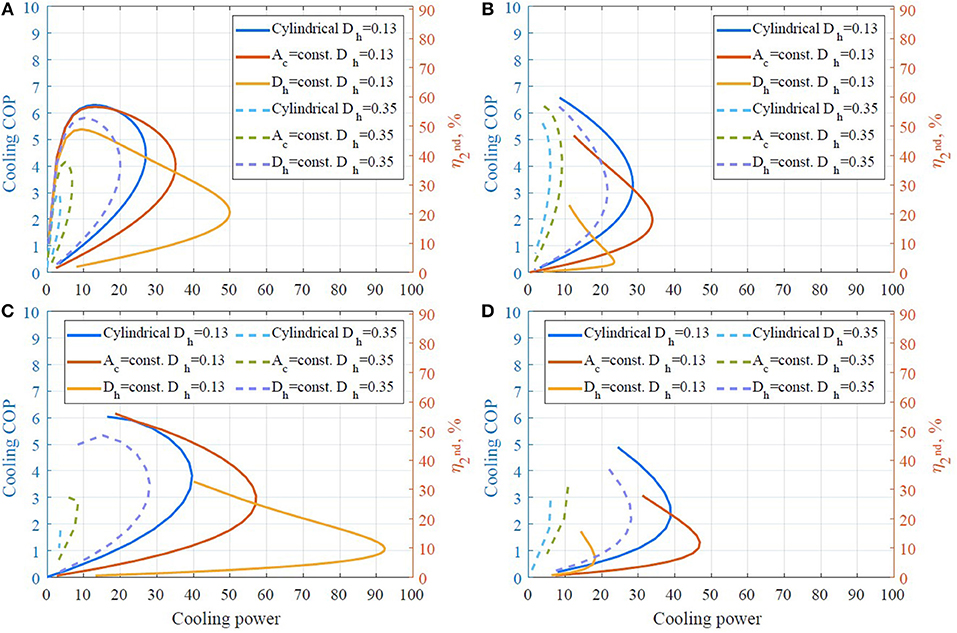
Figure 8. Cooling COP as a function of cooling power at ε = 0.27. (A) Cassette 1, ν = 0.5 Hz, (B) cassette 2, ν = 0.5 Hz, (C) cassette 1, ν = 2 Hz, (D) cassette 2, ν = 2 Hz.
It is worth mentioning that COP as a measure to evaluate performance of a cooling cycle is more widely accepted in industry. On the other hand, the second law efficiency is more relevant for the scientific community, since it allows to evaluate the performance of a system taking into consideration irreversibilities of the process. The actual COP (the first law efficiency) is calculated as given in Equation (14).
Where Wpump and Wmag are electric powers, required to drive a fluid pump and a motor that moves either regenerators or a magnet assembly, respectively. Both Wpump and Wmag are given in Equations (15) and (16), respectively.
The ideal or reversible COP is calculated as given in Equation (17).
The second law efficiency is the ratio between the actual COP and the reversible COP of the same system, as it is seen in Equation (18).
Inspecting Figures 8–11, one can see that cassette 1 (the shorter regenerator) performs significantly better in all the investigated conditions compared to cassette 2. Although, similar values for cooling COP can be obtained using either geometry, cassette 1 gives a higher cooling power for every modeled case. These findings are explained further in the discussion.
In Figures 8–11, one can see that the performance of all AMRs with structured flow channels is significantly higher when the hydraulic diameter of the flow channels is Dh = 0.13 mm compared to 0.35 mm. The smaller hydraulic diameter results in higher heat transfer and therefore higher cooling power and efficiency. Comparing model results for cassette 1 and cassette 2 (see, for example, Figures 8A,B), the straight cylindrical channels perform much better than the corrugated channels for the longer cassette 2. Conversely, for the shorter cassette 1, the corrugated channels can accept a larger cooling load and the AMR with double corrugated channels with constant Ac also operates at approximately equal or higher efficiency.
In Figure 9C, it can be seen that the maximum Qcool, obtained with the AMR with double corrugated channels with constant Ac with Dh = 0.13 mm, approaches the maximum Qcool, obtained with the AMR with packed spherical particles. Moreover, the previous regenerator establishes slightly higher cooling COP. On the other hand, in Figure 9D, it is seen these two regenerators perform almost identically if used in cassette 2. There a fine structure of cylindrical micro-channel matrix demonstrates superior performance. This finding agrees with the statement made in section AMR Geometries.
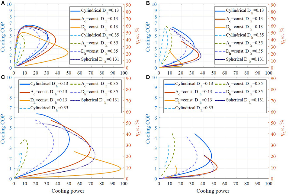
Figure 9. Cooling COP as a function of cooling power at ε = 0.36. (A) Cassette 1, ν = 0.5 Hz, (B) cassette 2, ν = 0.5 Hz, (C) cassette 1, ν = 2 Hz, (D) cassette 2, ν = 2 Hz.
In addition, in Figures 8–11, it is seen that the maximum cooling power for all the regenerators decreases with increasing porosity, as the mass of MCM decreases with increasing porosity. It is especially noticeable for AMRs with a flow channel size Dh = 0.13 mm. Moreover, AMRs with double corrugated flow patterns provides significantly higher maximum Qcool compared to the AMR with the cylindrical micro-channel matrix, although generally at a lower efficiency. One can also see that the cooling COP, established by the AMR with double corrugated flow patterns is higher than for the AMR with the cylindrical micro-channel matrix, at maximum Qcool for the later regenerator. For example, the AMR with double corrugated tube with constant Ac provides cooling COP of 4.9 while it is 3.9 for the AMR with the cylindrical micro-channel matrix at Qcool = 50 W, as it is seen in Figure 9C. In Figure 10C one can note that AMR with double corrugated tube with constant Ac provides cooling COP of 4.0 at Qcool = 65 W, while AMR with the cylindrical micro-channel matrix cannot establish such high cooling power.
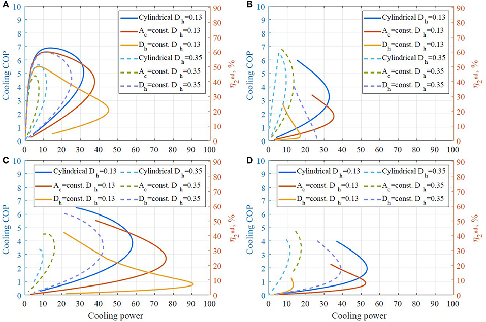
Figure 10. Cooling COP as a function of cooling power at ε = 0.45. (A) Cassette 1, ν = 0.5 Hz, (B) cassette 2, ν = 0.5 Hz, (C) cassette 1, ν = 2 Hz, (D) cassette 2, ν = 2 Hz.
One main conclusion from the results presented in Figures 8–11 is that the double corrugated tubes present a generally similar trend as the cylindrical channels. In some cases, the double corrugated tubes can produce higher cooling power at a reduced COP but in others, Figure 8A for example, the corrugated tubes outperform the cylindrical channels over the entire cooling capacity range. These model predictions show that each corrugation structure gives different performance but the double corrugated geometry does have the potential to outperform cylindrical channels provided that the corrugation pattern is well-suited to the operating conditions of the regenerator.
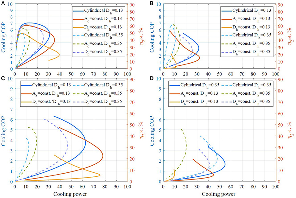
Figure 11. Cooling COP as a function of cooling power at ε = 0.54. (A) Cassette 1, ν = 0.5 Hz, (B) cassette 2, ν = 0.5 Hz, (C) cassette 1, ν = 2 Hz, (D) cassette 2, ν = 2 Hz.
One can see that performance of AMRs with the cylindrical micro-channel matrix and the double corrugated channels with Ac constant decreases significantly with increased hydraulic diameter of the flow channels as shown in Figures 8–11.
On the other hand, the AMR with double corrugated channels with constant Dh demonstrates an increase in COP at maximum cooling power when the size of the flow channels increased from 0.13 to 0.35 mm. Despite the fact that the maximum cooling power decreased significantly for the AMR with larger size of flow channels, it demonstrates rather similar performance to the AMRs with a flow channel size of 0.13 mm. For the purpose of comparison at a single operating condition, the performance of all modeled regenerators was analyzed at a cooling power, Qcool of 40 W, and the best results are presented in Table 4. Regenerators that could not accept a 40 W cooling load were omitted from the comparison.
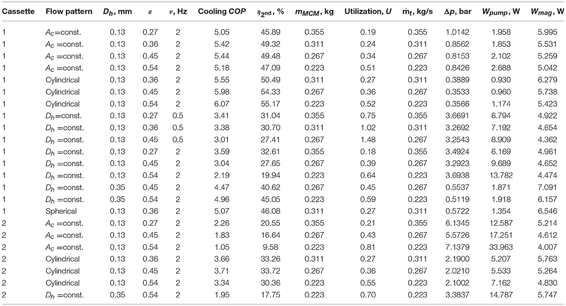
Table 4. Performance of all modeled regenerators at Qcool = 40 W.
Again, one can note, that cassette 1 demonstrated significantly higher efficiency than cassette 2 at the given cooling load conditions regardless of the used AMR flow pattern. This is caused by two major factors. First, the heat transfer is lower for longer flow channels than for short as it is seen in Equation (4). The difference in Nusselt number obtainable by the short (cassette 1) and long (cassette 2) geometries increases with increasing Reynolds number. Thus, cassette 1 has the potential to establish higher cooling power than cassette 2. The second factor contributing to the efficiency of the AMRs is pressure drop. Cassette 2 is longer than cassette 1, thus exhibits higher pressure drop at the same Reynolds number. In other words, theoretical performance of cassette 2 is limited to lower heat transfer at higher pressure drop compared to cassette1.
One also can see from Figures 8–11 and Table 4 that the highest second law efficiency between 49 and 55% can be obtained with sufficiently fine ordered structures of AMRs. Nevertheless, AMRs with packed spherical particles demonstrate of 46% followed by AMRs with double corrugated geometry with Dh = const., ε = 0.54 and channel size of 0.35 mm that establishes of 45%.
In Table 4, one can see that the maximum cooling COP of 6.0 was established by cassette 1 with the cylindrical micro-channel matrix with Dh = 0.13, ε = 0.54 mm at ν = 2 Hz. The AMR with constant Ac with Dh = 0.13 mm demonstrated cooling COP above 5.0. Moreover, the AMRs with cylindrical micro-channels matrix and constant Ac with ε ≤ 0.36 and Dh = 0.13 mm outperformed the AMR with spherical particles. However, fabrication of such narrow flow channels is challenging and practically such performance might be not obtainable due to inaccuracies caused by the manufacturing process.
On the other hand, cassette 1 with packed spherical particles with ε = 0.36 mm at ν = 2 Hz provides a COP of 5.0. It is technically possible to manufacture spheres with diameter of 0.35 mm (which is considered in this study). Nevertheless, it is impossible to assure even size and shape of the fabricated particles. This also leads to degradation of the AMR performance.
Finally, cassette 1 with double corrugated flow pattern with constant Dh with Dh = 0.35, ε = 0.54 mm at ν = 2 Hz demonstrated a COP of 4.9. It is noticeable that mass of MCM in the later regenerator is 28% lower than in cassette 1 with packed spherical particles. This means, that similar performance of AMR could be obtained using less MCM. This would lead to reduction of investment cost of a magnetocaloric heat pump.
Results presented here show that the double corrugated flow channels and cylindrical flow channels generally perform similarly, although each has its own advantages and disadvantages. This leads us to conclude that neither PEC nor the ratio of Nu to f can give a definitive characterization of an AMR geometry. Actual AMR performance can depend on a number of aspects and modeling the system COP remains the best method to evaluate a given geometry. However, both methods do give a general comparison of geometries.
Figure 12 presents the total power consumption of each regenerator that demonstrates cooling COP > 4.0 at Qcool = 40 W. One can see that the magnetic work is the lowest for the AMR with the double corrugated tube with constant Ac comparing regenerators with the same mass of MCM. However, an increase in consumed pumping power leads to a reduction of cooling COP compared to the AMR with the cylindrical micro-channel matrix. On the other hand, the AMR with packed spherical particles and with the double corrugated tube with constant Dh (ε = 0.54) show very similar required magnetic work. The main difference between the two is higher required pumping power for the later regenerator, which leads to a marginal reduction of cooling COP of the later AMR.
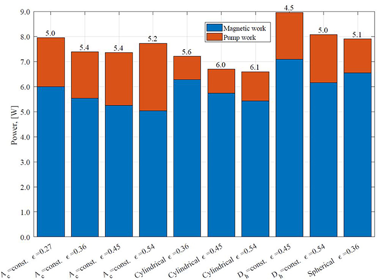
Figure 12. Total power consumption of AMR that demonstrates cooling COP > 4.0 at Qcool = 40 W (from Table 4).
In addition, the initial results of this study suggest that the PEC criterion is not relevant for selecting a flow pattern based on the double corrugated geometry. The PEC criterion was initially developed for evaluating global performance of enhanced geometries at the same operational conditions as for a reference geometry (Webb and Kim, 1994). This criterion, after some modifications, could be used for evaluating performance of enhanced geometries at constant: pumping power; flow rate; heat transfer surface area; heating duty, and etc. (Webb and Kim, 1994). However, none of these evaluation criteria provides boundary conditions, suitable for AMR application. For example, PEC with constant heating duty condition would lead to reduced length of an enhanced geometry. This is not applicable when performance of different AMR is compared. Moreover, the PEC criterion has been developed for evaluating an enhanced heat transfer rate over increase in friction factor, i.e., an enhanced geometry is considered to be more efficient than a reference geometry if the previous demonstrates greater increase in Nusselt number than it is in friction factor. On the other hand, AMR geometries are compared in terms of constant cooling power. Thus, a more performance efficient AMR would demonstrate higher cooling COP at the same Qcool.
Simulation results, presented in this article, demonstrate that AMRs with sufficiently fine flow structures based on cylindrical micro-channels or double corrugated geometry could provide significantly higher efficiency than packed spherical particle AMRs, although, experimental results reported up to now demonstrate that AMRs with packed spherical particles provide the best performance. In addition, the porosity of the previous regenerators can be increased up to 0.54. Thus, exploitation of MCMs could be improved in MCE-driven devices. Similar findings were presented in Lei et al. (2017) and Trevizoli et al. (2017). There authors concluded that AMRs with packed screen bed (Lei et al., 2017) and pin array (Trevizoli et al., 2017) have the potential to outperform AMRs with packed spherical particles. Nevertheless, the main issue is expensive and time-consuming fabrication of the pin arrays and woven screens (Lei et al., 2017; Trevizoli et al., 2017). Findings of this study relate to Trevizoli et al. (2017) and Lei et al. (2017) in a way, that the current technical limitations of SLM and LBM may introduce certain restrictions to the manufacturing process of AMR with double corrugated flow patterns. For example, minimum possible wall thickness or hydraulic diameter of the flow channels.
Conclusions
In this article, a nature-inspired solution for the flow structure of a porous structure of an AMR was presented. The performance of such an AMR with double corrugated flow pattern was investigated numerically using a 1D AMR model. The obtained results were compared with the numerical performance of an AMR with conventional flow structures, namely, packed spherical particles and a cylindrical microchannel matrix. Regenerators with two different lengths were considered based on two existing magnetocaloric devices. Two sizes of hydraulic diameters of the flow channels as well as various porosities were investigated.
From the numerical results, it is shown that the double corrugated geometry has a potential to be applied as a flow pattern for a porous AMR structure. When the corrugation pattern is matched to the desired operating conditions, higher cooling capacity and efficiency can be achieved. A suitably optimized double corrugated geometry demonstrates the potential to reduce the amount of required MCM in order to achieve similar efficiency as an AMR with conventional geometries. This reduces the investment cost of a magnetocaloric device. Nevertheless, experimental validation of the numerical results is required in order to confirm the true potential of AMRs with double corrugated patterns as well as the technical limitations of the manufacturing process.
The proposed nature-inspired double corrugated flow patterns for a solid AMR provides significant increase in maximum cooling power compared to the conventional AMR flow structures, especially compared to cylindrical microchannels. Moreover, the established cooling COP still would be rather high. This means that the nature-inspired double corrugated geometry is more efficient than conventional flow structures of a solid AMR. In order to validate the numerical results, an experimental investigation on AMRs with nature-inspired flow structure is pending.
Data Availability
The datasets generated for this study are available on request to the corresponding author.
Author Contributions
KE and CB supervised the process. KN run simulations and wrote the manuscript.
Conflict of Interest Statement
The authors declare that the research was conducted in the absence of any commercial or financial relationships that could be construed as a potential conflict of interest.
Supplementary Material
The Supplementary Material for this article can be found online at: https://www.frontiersin.org/articles/10.3389/fenrg.2019.00068/full#supplementary-material
Supplementary Video 1. 3D segment of a nature-inspired active magnetic regenerator.
References
Aprea, C., Cardillo, G., Greco, A., Maiorino, A., and Masselli, C. (2015). A comparison between experimental and 2D numerical results of a packed-bed active magnetic regenerator, Appl. Therm. Eng. 90, 376–383. doi: 10.1016/j.applthermaleng.2015.07.020
Aprea, C., Cardillo, G., Greco, A., Maiorino, A., and Masselli, C. (2016). A rotary permanent magnet magnetic refrigerator based on AMR cycle. Appl. Therm. Eng. 101, 699–703. doi: 10.1016/j.applthermaleng.2016.01.097
Aprea, C., Greco, A., and Maiorino, A. (2012). Modelling an active magnetic refrigeration system: a comparison with different models of incompressible flow through a packed bed. Appl. Therm. Eng. 36, 296–306. doi: 10.1016/j.applthermaleng.2011.10.034
Arnold, D. S., Tura, A., Ruebsaat-Trott, A., and Rowe, A. (2014). Design improvements of a permanent magnet active magnetic refrigerator, Int. J. Refrig. 37, 99–105. doi: 10.1016/j.ijrefrig.2013.09.024
Bahl, C. R. H., Navickaite, K., Neves Bez, H., Lei, T., Engelbrecht, K., Shen, B., et al. (2017). Operational test of bonded magnetocaloric plates, Int. J. Refrig. 76, 245–251. doi: 10.1016/j.ijrefrig.2017.02.016
Balli, M., Jandl, S., Fournier, P., and Kedous-Lebouc, A. (2017). Advanced materials for magnetic cooling: fundamentals and practical aspects. Appl. Phys. Rev. 4:021305. doi: 10.1063/1.4983612
Bouchard, J., Nesreddine, H., and Galanis, N. (2009). Model of a porous regenerator used for magnetic refrigeration at room temperature. Int. J. Heat Mass Transf. 52, 1223–1229. doi: 10.1016/j.ijheatmasstransfer.2008.08.031
Brown, G. V. (1976). Magnetic heat pumping near room temperature. J. Appl. Phys. 47, 3673–3680. doi: 10.1063/1.323176
Dall'Olio, S., Eriksen, D., Engelbrecht, K., Insinga, A. R., and Bahl, C. R. H. (2017). “Design, enhanced thermal and flow efficiency of a 2 kW active magnetic regenerator,” in 9th World Conferences on Experimental Heat Transfer, Fluid Mechanics and Thermodynamics. (Foz do Iguaçu).
Dickson, K. A., and Graham, J. B. (2004). Evolution and consequences of endothermy in fishes. Physiol. Biochem. Zool. 77, 998–1018. doi: 10.1086/423743
Engelbrecht, K. (2019). Future prospects for elastocaloric devices. J. Phys. Energy. 1:021001. doi: 10.1088/2515-7655/ab1573
Engelbrecht, K., Nellis, G. F., and Klein, S. A. (2006). The effect of internal temperature gradients on regenerator matrix performance. J. Heat Transfer 128, 1060–1069. doi: 10.1115/1.2345428
Engelbrecht, K., Tušek, J., Nielsen, K. K., Kitanovski, A., Bahl, C. R. H., and Poredoš, A. (2013). Improved modelling of a parallel plate active magnetic regenerator. J. Phys. D Appl. Phys. 46:255002. doi: 10.1088/0022-3727/46/25/255002
Ergun, S., and Orning, A. A. (1949). Fluid flow through randomly packed columns and fluidized beds. Ind. Eng. Chem. 41, 1179–1184. doi: 10.1021/ie50474a011
Eriksen, D., Engelbrecht, K., Bahl, C. R. H., Bjørk, R., and Nielsen, K. K. (2016). Effects of flow balancing on active magnetic regenerator performance. Appl. Therm. Eng. 103, 1–8. doi: 10.1016/j.applthermaleng.2016.03.001
Eriksen, D., Engelbrecht, K., Bahl, C. R. H., Bjørk, R., Nielsen, K. K., Insinga, A. R., et al. (2015). Design and experimental tests of a rotary active magnetic regenerator prototype. Int. J. Refrig. 58, 14–21. doi: 10.1016/j.ijrefrig.0.2015.05.004
European Commission (2013). European Commissioner Connie Hedegaard Welcomes Major Step Forward to Reduce Some of the Most Dangerous Greenhouse Gases, Press Release Database. European Commission.
Goetzler, W., Zogg, R., Young, J., and Johnson, C. (2014). Energy Savings Potential and RDandamp;DOpportunities for Non-Vapor-Compression HVAC Technologies. Burlington, VT.
Jacobs, S., Auringer, J., Boeder, A., Chell, J., Komorowski, L., Leonard, J., et al. (2014). The performance of a large-scale rotary magnetic refrigerator. Int. J. Refrig. 37, 84–91. doi: 10.1016/j.ijrefrig.2013.09.025
Johra, H., Filonenko, K., Heiselberg, P., Veje, C., Lei, T., and Dall'Olio, S. (2018). Integration of a magnetocaloric heat pump in a low-energy residential building. Build. Simul. 11, 753–763. doi: 10.1007/s12273-018-0428-x
Kitanovski, A., Tušek, J., Tomc, U., Plaznik, U. M., OŽbolt, M., and Poredoš, A. (2015). Magnetocaloric Energy Conversion. From Theory to Applications. Springer International Publishing. doi: 10.1007/978-3-319-08741-2
Lei, T. (2016). Modeling of active magnetic regenerators and experimental investigation of passive regenerators with oscillating flow (Ph.D. thesis). Technical University of Denmark, Risø, Denmark.
Lei, T., Engelbrecht, K., Nielsen, K. K., and Veje, C. T. (2017). Study of geometries of active magnetic regenerators for room temperature magnetocaloric refrigeration, Appl. Therm. Eng. 111, 1232–1243. doi: 10.1016/j.applthermaleng.2015.11.113
Lei, T., Navickaite, K., Engelbrecht, K., Barcza, A., Vieyra, H., Nielsen, K. K. C., et al. (2018). Passive characterization and active testing of epoxy bonded regenerators for room temperature magnetic refrigeration. Appl. Therm. Eng. 128, 10–19. doi: 10.1016/j.applthermaleng.2017.08.152
Li, J., Numazawa, T., Matsumoto, K., Yanagisawa, Y., and Nakagome, H. (2012). A modeling study on the geometry of active magnetic regenerator. AIP Conf. Proc. 1434, 327–334. doi: 10.1063/1.4706936
Li, J., Numazawa, T., Matsumoto, K. M., Yanagisawa, Y., and Nakagome, H. (2014). Comparison of different regenerator geometries for AMR system. AIP Conf. Proc. 1573, 548–554. doi: 10.1063/1.4860749
Liu, M., and Yu, B. (2011). Numerical investigations on internal temperature distribution and refrigeration performance of reciprocating active magnetic regenerator of room temperature magnetic refrigeration. Int. J. Refrig. 34, 617–627. doi: 10.1016/j.ijrefrig.2010.12.003
Lyubina, J. (2017). Magnetocaloric materials for energy efficient cooling. J. Phys. D. Appl. Phys. 50:053002. doi: 10.1088/1361-6463/50/5/053002
Maiorino, A., Del Duca, M. G., Tušek, J., Tomc, U., Kitanovski, A., and Aprea, C. (2019). Evaluating magnetocaloric effect in magnetocaloric materials: a novel approach based on indirect measurements using artificial neural networks, Energies 12:1871. doi: 10.3390/en12101871
Monfared, B. A. (2018a). Magnetic Refrigeration for Near Room-Temperature Applications. KTH Royal Institute of Technology.
Monfared, B. A. (2018b). Design and optimization of regenerators of a rotary magnetic refrigeration device using a detailed simulation model. Int. J. Refrig. 88, 260–274. doi: 10.1016/j.ijrefrig.2018.01.011
Moore, J. D., Klemm, D., Lindackers, D., Grasemann, S., Träger, R., Eckert, J., et al. (2013). Selective laser melting of La(Fe,Co,Si) 13 geometries for magnetic refrigeration. J. Appl. Phys. 114:043907. doi: 10.1063/1.4816465
Munson, B. R., Young, D. F., and Okishi, T. H. (2002). Fundamentals of Fluid Mechanics, 4th Edn. John Wiley and Sons.
Nakashima, A. T. D., Dutra, S. L., Trevizoli, P. V., and Barbosa, J. R. (2018). Influence of the flow rate waveform and mass imbalance on the performance of active magnetic regenerators. Part I: experimental analysis. Int. J. Refrig. 93, 236–248. doi: 10.1016/j.ijrefrig.2018.07.004
Navickaite, K., Cattani, L., Bahl, C. R. H., and Engelbrecht, K. (2019a). Elliptical double corrugated tubes for enhanced heat transfer. Int. J. Heat Mass Transf. 128, 363–377. doi: 10.1016/j.ijheatmasstransfer.2018.09.003
Navickaite, K., Mocerino, A., Cattani, L., Bozzoli, F., Liltrop, K., Zhang, X. C., et al. (2019c). Engelbrecht, enhanced heat transfer in tubes based on vascular heat exchangers in fish: experimental investigation. Int. J. Heat Mass Transf. 137, 192–203. doi: 10.1016/j.ijheatmasstransfer.2019.03.067
Navickaite, K., Mocherino, A., Cattani, L., Bozzoli, F., Bahl, C. R. H., and Engelbrecht, K. (2019b). “Heat transfer in double corrugated tubes,” in 9th REMOO International Conference of Work (Hong Kong).
Navickaite, K., Monfared, B. A., Martinez, D., Palm, B., Bahl, C. R. H., and Engelbrecht, K. (2018a). “Experimental investigation of fifteen-layer epoxy-bonded La(Fe,Mn,Si)13Hy ctive magnetic regenerator,” in 8th International Conference on Caloric Cooling (Darmstadt).
Navickaite, K., Neves Bez, H., Lei, T., Barcza, A., Vieyra, H., Bahl, C. R. H., et al. (2018b). Experimental and numerical comparison of multi-layered La(Fe,Si,Mn)13Hy active magnetic regenerators. Int. J. Refrig. 86, 322–330. doi: 10.1016/j.ijrefrig.2017.10.032
Nielsen, K. K., Tušek, J., Engelbrecht, K., Schopfer, S., Kitanovski, A., Bahl, C. R. H., et al. (2011). Review on numerical modeling of active magnetic regenerators for room temperature applications. Int. J. Refrig. 34, 603–616. doi: 10.1016/j.ijrefrig.2010.12.026
Provenzano, V., Shapiro, A. J., and Shull, R. D. (2004). Reduction of hysteresis losses in the magnetic refrigerant Gd5Ge2Si2 by the addition of iron. Nature 429, 853–857. doi: 10.1038/nature02657
Smith, A., Bahl, C. R. H., Bjørk, R., Engelbrecht, K., Nielsen, K. K., and Pryds, N. (2012). Materials challenges for high performance magnetocaloric refrigeration devices. Adv. Energy Mater. 2, 1288–1318. doi: 10.1002/aenm.201200167
Trevizoli, P. V., and Barbosa, J. R. Jr. (2017). Entropy generation minimization analysis of active magnetic regenerators. An. Acad. Bras. Cienc. 89, 717–743. doi: 10.1590/0001-3765201720160427
Trevizoli, P. V., Nakashima, A. T., Peixer, G. F., and Barbosa, J. R. Jr. (2017). Performance assessment of different porous matrix geometries for active magnetic regenerators. Appl. Energy 187, 847–861. doi: 10.1016/j.apenergy.2016.11.031
Trevizoli, P. V., Peixer, G. F., Nakashima, A. T., Capovilla, M. S., Lozano, J. A., and Barbosa, J. R. (2018). Influence of inlet flow maldistribution and carryover losses on the performance of thermal regenerators. Appl. Therm. Eng. 133, 472–482. doi: 10.1016/j.applthermaleng.2018.01.055
Trevizoli, P. V., Teyber, R., da Silveira, P. S., Scharf, F., Schillo, S. M., Niknia, I., et al. (2019). Thermal-hydraulic evaluation of 3D printed microstructures. Appl. Therm. Eng. 160:113990. doi: 10.1016/j.applthermaleng.2019.113990
Tušek, J., Kitanovski, A., and Poredoš, A. (2013a). Geometrical optimization of packed-bed and parallel-plate active magnetic regenerators. Int. J. Refrig. 36, 1456–1464. doi: 10.1016/j.ijrefrig.2013.04.001
Tušek, J., Kitanovski, A., Prebil, I., and Poredoš, A. (2011). Dynamic operation of an active magnetic regenerator (AMR): numerical optimization of a packed-bed AMR. Int. J. Refrig. 34, 1507–1517. doi: 10.1016/j.ijrefrig.2011.04.007
Tušek, J., Kitanovski, A., Zupan, S., Prebil, I., and Poredoš, A. (2013b). A comprehensive experimental analysis of gadolinium active magnetic regenerators. Appl. Therm. Eng. 53, 57–66. doi: 10.1016/j.applthermaleng.2013.01.015
Velázquez, D., Estepa, C., Palacios, E., and Burriel, R. (2016). A comprehensive study of a versatile magnetic refrigeration demonstrator. Int. J. Refrig. 63, 14–24. doi: 10.1016/j.ijrefrig.2015.10.006
Velázquez, D., Palacios, E., Estepa, C., and Burriel, R. (2014). “A versatile magnetic refrigeration demonstartor,” in 6th International Conference on Caloric Cooling. (Victoria, BC).
Wakao, N., and Kaguei, S. (1982). Heat and Mass Transfer in Packed Beds. New York, NY: Gordon and Breach Science Publishers.
Webb, R. L., and Kim, N. H. (1994). Principles of Enhanced Heat Transfer, 2nd Edn. Abingdon, Taylor and Francis CRC ebook account.
Wegner, N. C., Snodgrass, O. E., Dewar, H., and Hyde, J. R. (2015). Whole-body endothermy in a mesopelagic fish, the opah, Lampris guttatus. Science 348, 786–789. doi: 10.1126/science.aaa8902
Wieland, S., Kagathara, J., Gärtner, E., Uhlenwinkel, V., and Steinbacher, M. (2018). “Powder, process parameters and heat treatment conditions for laser beam melting of LaFeSi-based alloys,” in 8th International Conference on Caloric Cooling (Darmstadt).
Zimm, C., Boeder, A., Mueller, B., Rule, K., and Russek, S. L. (2018). The evolution of magnetocaloric heat-pump devices. MRS Bull. 43, 274–279. doi: 10.1557/mrs.2018.71
Nomenclature
Keywords: magnetocaloric heat pump, active magnetic regenerators, biomimetics, AMR modeling, solid state cooling
Citation: Navickaitė K, Bahl C and Engelbrecht K (2019) Nature—Inspired Flow Patterns for Active Magnetic Regenerators Assessed Using a 1D AMR Model. Front. Energy Res. 7:68. doi: 10.3389/fenrg.2019.00068
Received: 11 June 2019; Accepted: 08 July 2019;
Published: 23 July 2019.
Edited by:
Angelo Maiorino, University of Salerno, ItalyReviewed by:
Reed Teyber, Lawrence Berkeley National Laboratory, United StatesPaulo V. Trevizoli, Federal University of Minas Gerais, Brazil
Jaka Tušek, University of Ljubljana, Slovenia
Copyright © 2019 Navickaitė, Bahl and Engelbrecht. This is an open-access article distributed under the terms of the Creative Commons Attribution License (CC BY). The use, distribution or reproduction in other forums is permitted, provided the original author(s) and the copyright owner(s) are credited and that the original publication in this journal is cited, in accordance with accepted academic practice. No use, distribution or reproduction is permitted which does not comply with these terms.
*Correspondence: Kurt Engelbrecht, a3VlbkBkdHUuZGs=