 Md. Arman Arefin
- Department of Mechanical Engineering, Rajshahi University of Engineering & Technology, Rajshahi, Bangladesh
The performance of photovoltaic (PV) panel is extremely sensitive to its operating temperature. Most of the energy absorbed by the panel is wasted in the form of heat and provides no value. Integrated photovoltaic thermal system can be a great solution to this problem. In this study, a numerical and experimental work is conducted on hybrid photovoltaic—thermal water heating system with front surface water cooling. First, a numerical analysis is conducted which is capable of describing various thermal parameters affecting the performance of photovoltaic panel and collector. The effect of supplying different mass flow rates of water over the individual photovoltaic and collector system and the overall system are examined thoroughly by experiment. The results of the numerical analysis are found in good agreement with the experimental analysis. Due to active cooling, it was also observed that the overall efficiency of the whole system is approximately five times higher than the efficiency of PV panel alone. Top surface cooling method significantly dropped the panel temperature and increased the panel efficiency by almost 1.5% with an overall system efficiency of around 80% where, PV and collector efficiencies are ~16 and 64%, respectively.
Introduction
Photovoltaic (PV) cell or panel is a device which converts solar light energy into electrical energy. Historically, most PV boards have been utilized for off framework purposes; thus, it can be viewed as a method for dodging improvement of long and expensive electrical cables to remote areas. The off-grid PV systems customarily utilize rechargeable batteries to store generated power which can run the cell for a couple of hours without daylight. PV installations can be ground mounted, wall mounted or roof-top mounted. It can be fixed or a solar tracker can be used for following the sun across the sky. Different PV materials offer a different level of efficiencies, with the present normal efficiency of a solar cell going from 10 to 20% (Lasnier, 2017). However, the low efficiency of the PV module is due to the reason that 80 to 90% of solar radiation is converted to heat (Bazilian et al., 2002). This loss heat can be recovered by using an integrated photovoltaic-thermal (PV/T) system. In addition to this, the requirement of large space for installing separate PV and the thermal system is the main concern for the development of integrated photovoltaic-thermal system.
In the last 40 years, scientists and engineers have developed several hybrid photovoltaic thermal water heating (PVT/W) systems. Wolf (1976), Florschuetz (1975), Florschuetz (1979), and Hendrie (1979) first experimented on PV/T system using water and air as coolant. The authors got more efficiency while using water as a coolant from the PV panel than air. In those researches, forced circulation water cooling was used. Raghuraman (1981) and Cox and Raghuraman (1985) experimented on Hybrid PVT/W system and focused on mainly PV panel cooling. The study described analytical calculations on PV panel and hybrid photovoltaic-thermal system and evaluated different design parameters of a hybrid PV/T system. Hamdy et al. (1988), O'Leary and Davis Clements (1980), and Al-Baali (1986) investigated on light concentrating PVT/W system. In these studies, solar light was concentrated on the PV panel and got more efficiency than typical one that time. Bhargava et al. (1991) worked on PVT/W framework and evaluated the packing factor and flow rate. The study combined an air heater with PV panel and used linear relation between temperature panel to calculate the efficiency and power output of the PV panel. Ogunjuyigbe et al. (2016) did similar type of research by mixed integral linear programming for calculation and defining different parameters. Staebler et al. (2002) worked on a glassless PVT/W system and found efficiency of 32.5%. The study showed that glass PV panel is more efficient than covered panels. Khelifa et al. (2015) presented modeling of PVT/W using both theoretical and experimental steps and claimed 69% efficiency with 55% from collector and 14.8% from PV panel. Tripanagnostopoulos et al. (2002) and Tonui and Tripanagnostopoulos (2007) worked on air and water type collector system and found water type provides more efficiency than air type. Ibrahim et al. (2011) performed an experiment on glazed and unglazed PVT/W system and enhanced the conductivity through the aluminum reflector. The study showed that aluminum reflector gives far better result in efficiency than any other reflector. Mojumdera et al. (2016) conducted a similar type of testing with a solar simulator. Fudholi et al. (2014) evaluated the thermal and electrical efficiency of the system in the solar radiation range 500–800 W/m2. In that study, a water cooling system was used and got a maximum thermal efficiency of about 68%. Khanjari et al. (2016) did research by mixing nano-fluid with water in PV/T system to enhance the thermal conductivity of water. The study also examined computational fluid dynamics (CFD) analysis of the system taking three types of fluid in consideration and found that by increasing the volumetric ratio of the nano-particle, thermal efficiency can be increased. Brottier (2016) investigated the performance and reliability of solar cell near Lyon. In this study, unglazed PV/T collector was used and the system couple provided enough water for a nuclear family. Al-Waeli et al. (2017) conducted a very deep review of hybrid PV/T systems. The authors evaluated and discussed different previous established methods, their efficiency and implementation. The study concluded that unglazed PV/T system gives more energy than other systems and adding nano-fluid in the system increases the efficiency even more. In the last few years, several works on hybrid PV/T water heating system can be found; most of them are for domestic purposes. The system can be positioned on the rooftop of a building. In a building envelop the use of efficient PV/T collectors can be far more advantageous than standard solar thermal and PV components, for an energetic point of view along with energy consideration and primary energy saving. An explicit dynamic model using sheet and tube concept of a single glazed flat plate water heating PV/T collector was designed by Chow (2003). The author discovered that the water cooling and fin efficiency and the bonding between the sheet underneath the cell and the collector affect the overall efficiency of the whole system. Using a metallic bond the fin, in a form of a metal tube, is normally connected to the PV module enable the heat to be transferred. This method ensured “no gap” or “zero gap” condition between the metal tube and PV module. Chow et al. (2005, 2007) experimented on PV/T water collector in China. In that experiment, an aluminum-alloy flat box with a rectangular or square shape channel was designed, constructed and installed. In these experiments, the author got an overall efficiency of about 65%. In another experiment on hybrid photovoltaic-thermosyphon water heating system with the natural circulation of water for residential application was performed and found that the final temperature of hot water produced by the system higher after 1-day exposure (Chow et al., 2006).
From the beginning of the PV/T system, the collector is positioned at the bottom of the PV panel. This system has been used for the last 40 years and its performance and characteristics have been assessed by many famous researchers and scholastics. These types of systems have issues regarding efficiency, installation, and the economy. In that system, due to the positioning of the collector at the bottom of the PV module, it cannot get solar radiation directly rather it absorbs heat from the loss heat of the PV panel. For that reason, though the efficiency of the PV panel increases, but the collector provides efficiency lower than its standard efficiency. Moreover, to improve the transfer of heat from the PV panel to collector it requires additional heat transfer material.
In recent years, a new method is proposed to flow the water through the top surface of the PV panel for improving the efficiency of panel. In 2018, Wu et al. (2018) provided an idea of integrating this technique of water cooling with a collector and developed integrated PV/T system. However, the authors only provided numerical analysis of the system describing the effect of cooling channel height and variation of solar radiation on the heat transfer characteristics and performance of the system. In this type of system, the collector is not positioned at the bottom of the panel (positioned outside through integration) and it gets solar radiation directly. For these reasons, the efficiency of the collector increases and eventually, the overall efficiency of the system is more than the conventional systems. However, this system is not yet fully developed because only one numerical research is available in literature. More developed numerical and experimental research is necessary for the validation of the system including the analysis of PV panel and collector water temperature, mass flow rate, panel and collector efficiency, loss of water due to evaporation, distribution of water temperature on the panel and inside the collector.
In this paper, an integrated PV/T water heating system with top surface water cooling is examined theoretically, numerically and experimentally. First, the whole system is designed and fabricated. Then, all the necessary and fundamental parameters such as PV panel and collector water temperature, mass flow rate, panel and collector efficiency, loss of water due to evaporation, distribution of water temperature over the panel and inside the collector etc. are evaluated. Experimental data are taken for several months for accuracy. Moreover, Numerical analysis is also provided for the validation of experimental data. This research is sufficient enough for the proper validation of the whole system.
Numerical Analysis
ANSYS software (version 15.0) was used to carry out all the simulations and Solidworks was used to build up the model geometry. Above the cell, the right side of the domain section has been defined as the outlet pressure at 0 (zero) relative pressure since the outlet is open to atmosphere. The cells of the geometry were set to a wall with a thickness of 0.0003 m. The bottom of the cavity is defined as water at a particular speed. The left and right side of the cavity was defined as adiabatic walls. Asymmetrical boundary condition was used for all the other sides of the geometry, which means a zero velocity and temperature gradient. The thickness is 0.15 m, 0.3 wide and 1.3 lengths to give the valid dimensions of existence hybrid solar collector.
The equations are solved for the conservation of the volume control to produce the velocity field and temperature of the water flow in the field and temperature PV cells. Convergence is performed when all the residues are likely to below 1.0E-6 in the computational domain. The geometric model and the domain of the fluid are generated using software ANSYS-15. The examination of the independence of the grid is performed to check the validity of the mesh quality and enhancement of the solution, which is taken here as a quality suitable mesh for the calculation. Table 1 shows the different values and boundary conditions used in the simulation and physical model of the simulation is shown in Figure 1 and mesh of the PV panel and collector are shown in Figure 2.
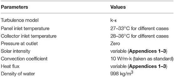
Table 1. Values used in the simulation.
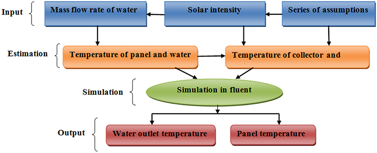
Figure 1. Physical model of the simulation.
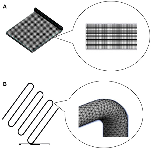
Figure 2. Mesh of (A) PV panel, (B) collector pipe.
The Reynolds number is calculated to define the turbulent model. The Reynolds number for 0.5 l/min, 1.l/min, 1.25 l/min, 1.5 l/min, 1.75 l/min, and 2 l/min are 356255.51, 712,511, 890,638, 1,068,766, 1,246,894, 1,425,022, respectively, where dynamic viscosity of water is taken at 28°C. Since the flow is turbulent, the k-ε turbulent model is selected as a model for a detailed analysis of the problem. Here, since the viscous sub-layer needs to be captured in cases of heat transfer phenomena and first cell has to be located within the viscous sub-layer, y+ has taken as <1, as this would provide reasonably accurate predictions for the majority of Reynolds number. The physical aspects of the flow of liquids are governed by the elementary principles: Continuity equation (mass conservation) and energy conservation equation. For the sake of solving these equations, the under-relaxation factors are used:
1. Here, the mass flow rate is taken as 0.5, 1, 1.25, 1.5, 1.75, and 2 L/min.
2. Outlet pressure Ps = Patm.
Materials and Methods
Experimental Setup
In this experiment, a water tank, a PV module, a flat plate collector and a storage tank is connected through a piping network. The capacity of the storage tank is 80 liters. The water tank is positioned 1 m above the solar module. The properties of the PV module are stated in Table 2. There is a valve between the tank and the module. When this valve is open, then water from the tank goes to the PV module. The water flows from the top surface of the PV module. For the flow of water a PVC pipe is positioned on the top of the PV module. There are 20 holes in the pipe to maintain a constant discharge. There is a tray at the bottom side of the module, which holds the module and provides support for which the water cannot flow down from the side of the PV module (Figure 3B). Water flows through the top surface of the module and extracts heat from the panel. After that, it goes to the collector inlet and being heated flow out through the collector outlet (collector properties are shown in Table 3). The heated water is finally stored in the insulated storage tank, which can be used for domestic uses later (Figure 3A).
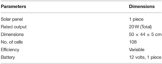
Table 2. Solar PV panel specifications.
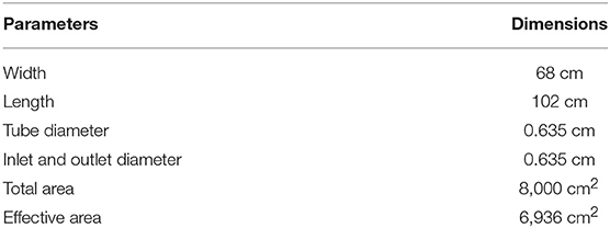
Table 3. Specifications of flat plate collector.
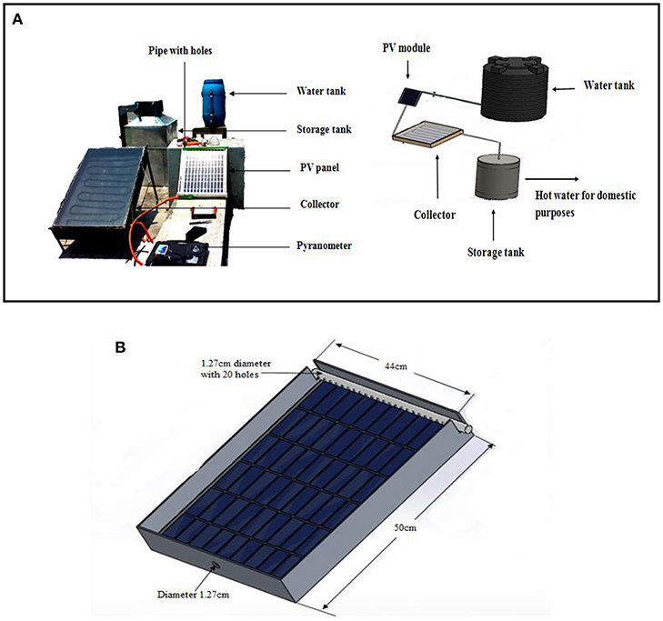
Figure 3. (A) Full experimental setup (B) PV panel setup.
Experimental Procedure
The main objectives of this study are to improve the efficiency of the photovoltaic panel by the natural flow of water from the top surface of the panel and then to enter this water in the collector inlet and get hot water from the outlet for domestic uses. The PV panel temperature and efficiency were determined without cooling for different tilt angles to find out the accurate tilt position which provides the best result in Rajshahi (Bangladesh). Then water was flowed from the top of the PV panel at those tilt positions and panel temperature and efficiency was determined. The tests were done for a different mass flow rates of water such as 0.5, 1, 1.25, 1.5, 1.75, and 2 L per minute. The water was supplied for 2 min in a 15 min interval because the continuous flow of water will reflect solar irradiation which eventually will reduce the efficiency of the PV panel. For this, an automatic control system was incorporated, where a programmable Arduino was used. A simple time delay code was imported in the Arduino which opens the valve for 2 min in 15 min interval. Then the water is supplied to the flat plate collector which is positioned in a place below the PV panel. The water is collected from the collector outlet and the temperature of the water is measured by a thermometer (accuracy ±1°C). The temperature of the PV panel is determined by the infrared thermometer device (accuracy ±1.5% of reading). All the readings were taken for several months from 10 a.m. to 4 p.m. of each day and the effective solar intensity was measured by the Pyranometer device (accuracy ±10 W/m2) in W/m2. Below Equations 1, 2, and 4 are used for determining the overall system efficiency, collector efficiency and PV panel efficiency, respectively. The performance of the PV/T collectors can be expressed by a combination of efficiency expressions consisting of thermal efficiency and electrical efficiency (He et al., 2011). These efficiencies usually include the ratio of the useful thermal gain and electrical gain of the system to the incident solar irradiation on the collector gap within a specific time or period (Fudholi et al., 2014).
Where, ηTotal is total system efficiency (%), ηthermalis thermal efficiency (%), ηelectrical is electrical efficiency (%), Isis solar intensity (W/m2), m is mass flow rate (kg/s), Cp is specific heat of fluid (joule/gram °C), Δt is inlet and outlet temperature difference (°C), I is current (A) and V is voltage (V), Aactual is the summation of the area for collector and the PV panel for thermal efficiency and area of PV panel for electrical efficiency(m2). Here, since the temperature difference of water before and after the PV panel is very less, the area of PV panel is neglected. The other reason of neglecting the PV panel area here is: with the change of tilt of the panel the useful heat would change too and considering this would make the calculation way too complicated.
Results and Discussion
Experimental data are shown in tabular form in Appendices 1–3, which were taken for 4 months continuously and data are taken as average in the tables. Figure 4 shows the voltage and current at a different time of a day for 4 different months with cooling. The panel has a voltage capacity of 22 V and current capacity of 1.5 A. The intensity of solar radiation controls the current, while with the increase of panel temperature voltage drops. The highest voltage obtained is 19.9 V and the lowest voltage obtained is 19.6 V. Highest current is found 1.2 A and the lowest was 1.07 A.
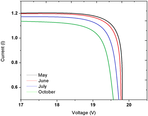
Figure 4. V-I diagram of the panel.
Figure 5 shows the PV panel temperature with and without water cooling (numerical and experimental). Six figures contain the values of four different day's readings from 1 p.m. to 4 p.m. of May, July, and October months. As the mass flow rate of water increases the panel temperature reduces. The higher the mass flow rate the more water can extract more heat from the panel. For 2 L/min of mass flow rate, the highest 12°C of panel temperature can be reduced which significantly increases the PV module efficiency.
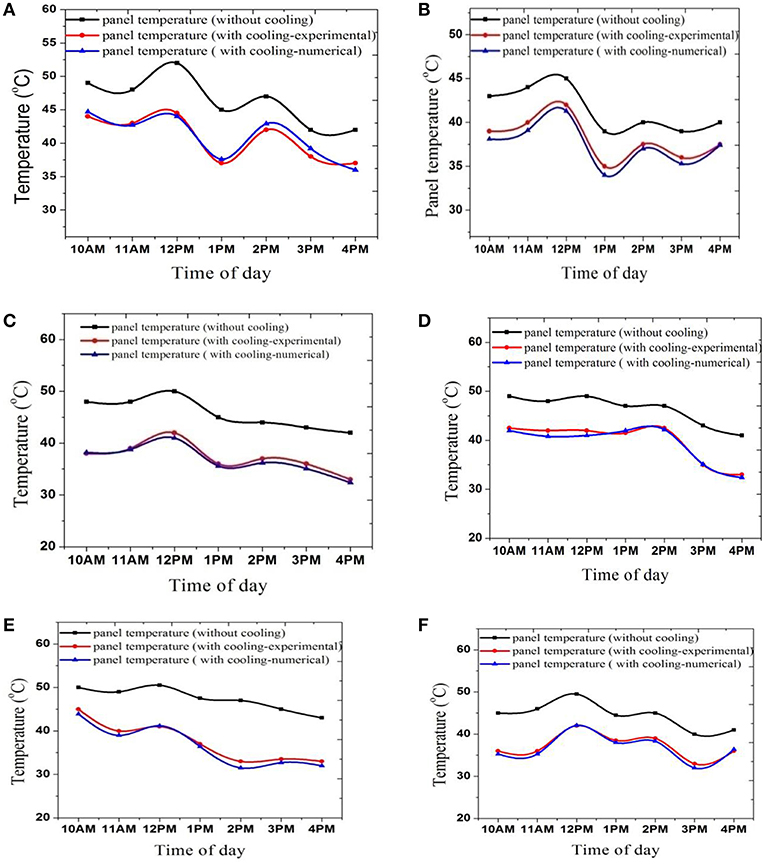
Figure 5. Panel temperature at (A) mw = 0.5 L/min, (B) mw = 1 L/min, (C) mw = 1.25 L/min, (D) mw = 1.5 L/min, (E) mw = 1.75 L/min, (F) mw = 2 L/min, respectively.
Figure 6 shows Temperature distribution of the photovoltaic panel (simulation Figure). Here, the outlet temperature of the water increases since it extracts some heat from the panel. The inlet temperature was given 295 K and the outlet temperature was obtained around 300 K. Panel temperature reduces from 48oC to 38oC. Here, the figure is for a mass flow rate of 1 L/min. All the simulations are done in the same procedure then results are calculated and finally all simulated results are plotted.
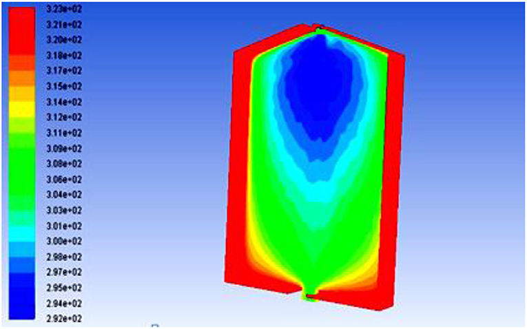
Figure 6. Temperature distribution of the photovoltaic panel.
With the increase of mass flow rate, the panel temperature reduces and efficiency increases (Figure 7). But, the efficiency and water temperature of the flat plate collector reduces. For the reduction of 1°C of panel temperature, the efficiency of panel increased by about 0.2–0.3%. In a photovoltaic cell with the increase of temperature above 25°C, the efficiency of PV panel falls. In this experiment, the highest temperature of the PV panel was obtained 52°C in a particular day, for which the efficiency was obtained around 11.23%. But for a temperature of 40°C the PV panel efficiency was obtained around 12.78%.
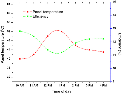
Figure 7. Variation of efficiency with panel temperature (Experimental).
Figure 8 shows the efficiency of the PV panel for different tilt angles with and without water cooling for three different days (day−1,−2, and−3). The highest efficiency of the panel without water cooling is obtained when it is tilted at 25° angle. As the angle of tilt increases, the efficiency of the panel decreases. The water cooling technique affects the efficiency most at 10° angle. For 10° angle the efficiency increases about 0.8%–0.9%, while for other tilt angles efficiency increases about 0.5–0.7%. For 0° angle the water cannot flow out from the panel continuously and in other positions (30°, 45°, 75°) the water leaves the panel surface too quickly. Therefore, the panel does not get enough time to get cooled.
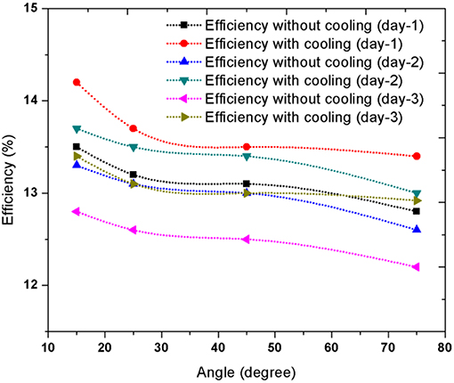
Figure 8. Efficiency without and with water cooling.
In this section, the efficiency of PV panel at different mass flow rates (0.5, 1, 1.25, 1.5, 1.75, 2 L/min) at 25° angle are shown in Figure 9. Results of 3 days are plotted and it is seen that with the increase of mass flow rate, the efficiency of PV panel increases. The more water passes over the surface of the PV panel the more heat it extracts from the PV panel and therefore, the temperature of the PV panel decreases. With the decrease of temperature, the efficiency of PV panel increases. For a mass flow rate of 0.5 L/min, an efficiency of 12% is obtained; but, for a mass flow rate of 2 L/min, an efficiency of 15.6% (approximately) is obtained.
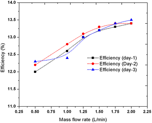
Figure 9. Efficiency of PV panel at different mass flow rates.
In the system, the mass loss of water is due to the evaporation of water and the leakage of water. When the water flows over the PV panel, due to extracting heat from the panel and solar radiation, some of the water gets evaporated. At lower mass flow rate, the evaporation rate is higher; but, as the flow rate increases, the rate of evaporation reduces (Figure 10). The leakage problem at all mass flow rate is almost zero, as all the visible and possible leakages were sealed properly during the experiment. In Figure 10, results of four different days (case 1, 2, 3, and 4) are shown to provide a proper idea, as mass loss is not a constant property rather it varies with solar intensity and temperature of the panel.
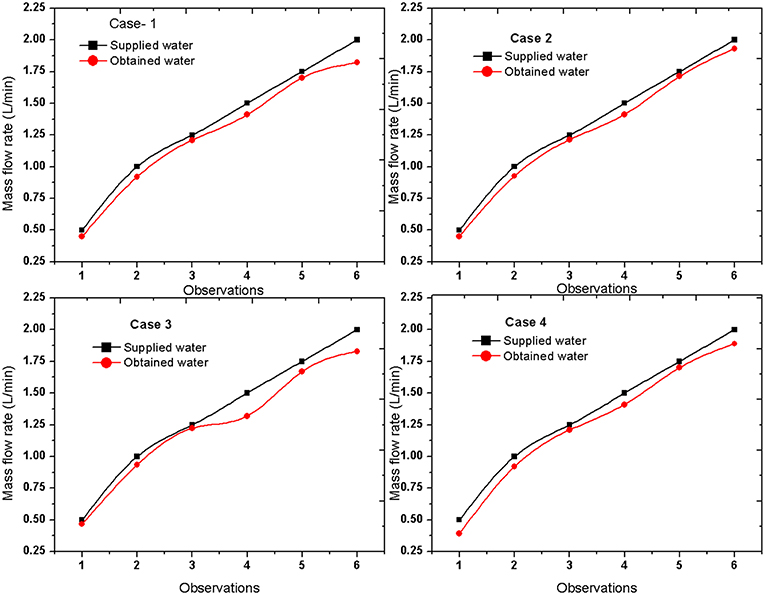
Figure 10. Mass loss of water.
Figure 11 shows the collector inlet and outlet temperature at a different mass flow rate. At a lower mass flow rate, the collector outlet temperature is comparatively higher than at higher mass flow rate. At lower mass flow rate, the water gets enough heat to get heated quickly; but, as the mass flow rate increases, the water does not get enough heat to get heated quickly. For 0.5 L/min mass flow rate, the highest temperature of the collector is obtained which is ~60°C and for 2 L/min the outlet temperature of water from the collector is obtained ~35°C, which is comparatively much lower than the other mass flow rates. However, in this experiment, the mass flow rates produce very small effect on the collector inlet temperature. This is due to the reason that the dimension on the PV panel is small the tilt angle of the panel in this section of the experiment was high. In addition, the amount of water is too high to get enough time to get heated properly.
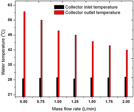
Figure 11. Collector inlet and outlet temperatures at different mass flow rates.
Figure 12 shows the temperature distribution of the water inside the collector. At a mass flow rate of 0.5 L/min, the temperature increases up to 60 K (obtained from the simulation). Simulations show quite similar results to the experiment. For the increase of the mass flow rate, the outlet water temperature decreases significantly. Same simulation procedure was used to determine the outlet temperature of different mass flow rates. The collector efficiency at different angles and mass flow rates are shown in Figure 13. At 0.5 L/min mass flow rate, the highest efficiency of 60% is obtained. Up to 70° of tilt angle, with the increase of angle the efficiency of collector increases. This is due to the reason that the water gets enough time to get heated. After this significant angle, the efficiency tends to decrease, because in vertical position collector does not get solar intensity properly.
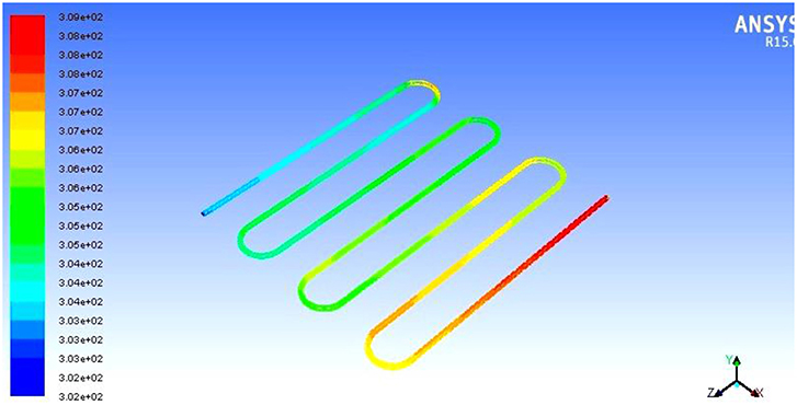
Figure 12. Distribution of the water inside the collector.
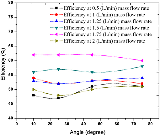
Figure 13. Collector efficiency at different angles and mass flow rates.
Flat plate collector efficiency of 50% is obtained on average in this experiment. Collector efficiency varies from 44 to 60% based on tilt angles and different mass flow rates, but the PV module efficiency increases as the mass flow rate increases as shown in Figure 9. So, theoretically at the highest mass flow rate, the overall system efficiency should be highest, however, in a practical case, this does not happen. From Figure 14, it is seen that at a mass flow rate of 1.75 L/min the overall system efficiency is highest. This is due to the reason that the overall efficiency is the combination of PV panel and collector efficiency. Though PV panel shows maximum efficiency at 2 L/min mass flow rate, collector shows maximum efficiency at 1.75 L/min. As a result, at 1.75 L/min mass flow rate the overall efficiency is highest. At this certain mass flow rate, the PV panel efficiency does not vary much, though the collector efficiency varies a lot. However, as mass flow rate increases, the outlet water temperature decreases (Figure 11). Therefore, the mass flow rate should be maintained according to desired water output.
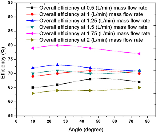
Figure 14. Overall efficiency of the system at different angles and mass flow rates.
Conclusion
In this research, a detailed study on integrated photovoltaic thermal water heating system is conducted through numerical and experimental analysis. The system is tested under the climatic condition of Bangladesh. Based on the results obtained the below conclusions are drawn:
1. A detailed numerical and experimental model capable of predicting various fundamental parameters including thermal and electrical performance of the system is developed and analyzed.
2. In the newly developed system, the collector is positioned outside the PV panel (connected through integration), which captures the hot water coming from the PV panel and produces high temperature water.
3. Photovoltaic panel efficiency is highly sensitive to panel temperature. With the increase of the mass flow rate the electrical efficiency of the PV panel increases. The top surface water cooling technique increased the PV panel efficiency by almost 0.8– 1.5%.
4. Flat plate solar collector efficiency was obtained about 46–65% for different cases.
5. The overall efficiency of the whole system is approximately five times higher than the efficiency of PV panel alone. Highest overall efficiency was obtained for a mass flow rate of 1.75 L/min, which was around 80% where, PV and collector efficiencies are ~16 and 64%.
6. There is a good agreement between the numerical and experimental results. The error between the experimental and numerical value was ~5%.
7. Finally, the system was validated numerically and experimentally.
Data Availability
All datasets generated for this study are included in the manuscript/Supplementary Files.
Author Contributions
The author confirms being the sole contributor of this work and has approved it for publication.
Conflict of Interest Statement
The author declares that the research was conducted in the absence of any commercial or financial relationships that could be construed as a potential conflict of interest.
Supplementary Material
The Supplementary Material for this article can be found online at: https://www.frontiersin.org/articles/10.3389/fenrg.2019.00097/full#supplementary-material
References
Al-Baali, A. A. (1986). Improving the power of a solar panel by cooling and light concentrating. Solar Wind Technol. 3, 241–245. doi: 10.1016/0741-983X(86)90002-0
Al-Waeli, A. H. A., Sopian, K., Kazem, H. A., and Chaican, M. T. (2017). Photovoltaic/Thermal (PV/T) systems: Status and future prospects. Renew. Sust. Energy Rev. 77, 109–130. doi: 10.1016/j.rser.2017.03.126
Bazilian, M. D., Kamalanathan, H., and Prasad, D. K. (2002). Thermographic analysis of a building integrated photovoltaic system. Renew. Energy 26, 449–461. doi: 10.1016/S0960-1481(01)00142-2
Bhargava, A. K., Garg, H. P., and Agarwal, R. K. (1991). Study of a hybrid solar system—solar air heater combined with solar cells. Energy Conver. Manag. 31, 471–479. doi: 10.1016/0196-8904(91)90028-H
Brottier, L. (2016). Field test results of an innovative PV/T collector for solar domestic hot water. Energy Proc. 91, 276–283. doi: 10.1016/j.egypro.2016.06.219
Chow, T. T. (2003). Performance analysis of photovoltaic-thermal collector by explicit dynamic model. Solar Energy 75, 143–152. doi: 10.1016/j.solener.2003.07.001
Chow, T. T., He, W., and Ji, J. (2006). Hybrid photovoltaic-thermosyphon water heating system for residential application. Solar Energy 80, 298–306. doi: 10.1016/j.solener.2005.02.003
Chow, T. T., Ji, J., and He, W. (2005). “Photovoltaic thermal collector system for domestic application,” in Proceedings of Solar World Congress (ISEC), 2005–76128. doi: 10.1115/ISEC2005-76128
Chow, T. T., Ji, J., and He, W. (2007). Photovoltaic-thermal collector system for domestic application. J. Solar Energy Eng. 129, 205–209. doi: 10.1115/1.2711474
Cox, C. H., and Raghuraman, P. (1985). Design considerations for flat-plate-photovoltaic/thermal collectors. Solar Energy 35, 227–241. doi: 10.1016/0038-092X(85)90102-1
Florschuetz, L. W. (1975). “On heat rejection from terrestrial solar cell arrays with sunlight concentration,” in 11th Photovoltaic Specialists Conference (New York, NY).
Florschuetz, L. W. (1979). Extension of the Hottel-Whillier model to the analysis of combined photovoltaic/thermal flat plate collectors. Solar Energy 22, 361–366. doi: 10.1016/0038-092X(79)90190-7
Fudholi, A., Sopian, K., Yazdi, M. H., Ruslan, M. H., Ibrahim, A., and Kazem, H. A. (2014). Performance analysis of photovoltaic thermal (PVT) water collectors. Energy Conv. Manag. 78, 641–651. doi: 10.1016/j.enconman.2013.11.017
Hamdy, M. Adel, Luttmann, F., and Osborn, D. (1988). Model of a spectrally selective decoupled photovoltaic/thermal concentrating system. Appl. Energy 30, 209–225. doi: 10.1016/0306-2619(88)90046-3
He, W., Zhang, Y., and Ji, J. (2011). Comparative experiment study on photovoltaic and thermal solar system under natural circulation of water. Appl. Therm. Eng. 31, 3369–3376. doi: 10.1016/j.applthermaleng.2011.06.021
Hendrie, S. D. (1979). Evaluation of Combined Photovoltaic/Thermal Collectors. No. COO-4577-8; CONF-790541-54. Massachusetts Inst. of Tech., Lexington: Lincoln Lab.
Ibrahim, M., Othman, Y., Ruslan, M. H., Mat, S., and Sopian, K. (2011). Recent advances in flat plate photovoltaic/thermal (PV/T) solar collectors. Renew. Sust. Energy Rev. 15, 352–365. doi: 10.1016/j.rser.2010.09.024
Khanjari, Y., Pourfayaz, F., and Kasaeian, A. B. (2016). Numerical investigation on using of nanofluid in a water-cooled photovoltaic thermal system. Energy Conv. Manag. 122, 263–278. doi: 10.1016/j.enconman.2016.05.083
Khelifa, A., Touafek, K., and Moussa, H. B. (2015). Approach for the modeling of hybrid photovoltaic–thermal solar collector. IET Renew. Power Gen. 9, 207–217. doi: 10.1049/iet-rpg.2014.0076
Mojumdera, J. C., Onga, H. C., Chong, W. T., Shamshirband, S., and AlMamoona, A. (2016). Application of support vector machine for prediction of electrical and thermal performance in PV/T system. Energy Build. 111, 267–277. doi: 10.1016/j.enbuild.2015.11.043
Ogunjuyigbe, A. S. O., Ayodele, T. R., and Oladimeji, O. E. (2016). Management of loads in residential buildings installed with PV system under intermittent solar irradiation using mixed integer linear programming. Energy Build. 130, 253–271. doi: 10.1016/j.enbuild.2016.08.042
O'Leary, M. J., and Davis Clements, L. (1980). Thermal-electric performance analysis for actively cooled, concentrating photovoltaic systems. Solar Energy 25, 401–406. doi: 10.1016/0038-092X(80)90446-6
Raghuraman, P. (1981). Analytical predictions of liquid and air photovoltaic/thermal, flat-plate collector performance. J. Solar Energy Eng. 103, 291–298. doi: 10.1115/1.3266256
Staebler, D. L., Uril, N. B., and Kiss, Z. S. (2002). “Development of High-efficiency hybrid PV-thermal modules,” in 29th IEEE Photovoltaic Specialists Conference (New Orleans, LA), 1660–1663. doi: 10.1109/PVSC.2002.1190936
Tonui, J. K., and Tripanagnostopoulos, Y. (2007). Air-cooled PV/T solar collectors with low-cost performance improvements. Solar Energy 81, 498–511. doi: 10.1016/j.solener.2006.08.002
Tripanagnostopoulos, Y., Nousia, T., Souliotis, M., and Yianoulis, P. (2002). Hybrid photovoltaic/thermal solar systems. Solar Energy 72, 217–234. doi: 10.1016/S0038-092X(01)00096-2
Wolf, M. (1976). Performance analyses of combined heating and photovoltaic power systems for residences. Energy Conver. 16, 79–90. doi: 10.1016/0013-7480(76)90018-8
Keywords: solar energy, hybrid PVT system, photovoltaic, collector, water cooling
Citation: Arefin MA (2019) Analysis of an Integrated Photovoltaic Thermal System by Top Surface Natural Circulation of Water. Front. Energy Res. 7:97. doi: 10.3389/fenrg.2019.00097
Received: 14 May 2019; Accepted: 27 August 2019;
Published: 18 September 2019.
Edited by:
Christos N. Markides, Imperial College London, United KingdomReviewed by:
Muthu Manokar A., B.S. Abdur Rahman University, IndiaRunsheng Tang, Yunnan Normal University, China
Gan Huang, Imperial College London, United Kingdom
Copyright © 2019 Arefin. This is an open-access article distributed under the terms of the Creative Commons Attribution License (CC BY). The use, distribution or reproduction in other forums is permitted, provided the original author(s) and the copyright owner(s) are credited and that the original publication in this journal is cited, in accordance with accepted academic practice. No use, distribution or reproduction is permitted which does not comply with these terms.
*Correspondence: Md. Arman Arefin, ZGlwdG83MEB5YWhvby5jb20=