 Vitor Monteiro
 Nima Tashakor
 Tiago J. C. Sousa1
 Joao L. Afonso
- 1ALGORITMI Research Centre, University of Minho, Campus de Azurem, Guimaraes, Portugal
- 2Lehrstuhl Mechatronic & Elektrische Antriebssysteme, Technische Universität (TU) Kaiserslautern, Kaiserslautern, Germany
With the objective of minimizing environment and energy issues, distributed renewable-energy sources have reached remarkable advancements along the last decades, with special emphasis on wind and solar photovoltaic installations, which are deemed as the future of power generation in modern power systems. The integration of renewable-energy sources into the power system requires the use of advanced power electronic converters, representing a challenge within the paradigm of smart grids, e.g., to improve efficiency, to obtain high power density, to guarantee fault tolerance, to reduce the control complexity, and to mitigate power-quality problems. This paper presents a specific review about front-end converters for renewable-energy applications (more specifically the power inverter that interfaces the renewable-energy source with the power grid). It is important to note that the objective of this paper is not to cover all types of front-end converters; the focus is only on single-phase multilevel structures limited to five voltage levels, based on a voltage-source arrangement and allowing current or voltage feedback control. The established review is presented considering the following main classifications: (a) number of passive and active power semiconductors; (b) fault tolerance features; (c) control complexity; (d) requirements of specific passive components as capacitor or inductors; and (e) number of independent or split dc-link voltages. Throughout the paper, several specific five-level front-end topologies are presented and comparisons are made between them, highlighting the pros and cons of each one of them as a candidate for the interface of renewable-energy sources with the power grid.
Introduction
Power converters capable of synthesizing, more than three voltage levels, are commonly classified as multilevel converters, where a common feature is the possibility to deal with higher voltages (Pandey et al., 2006; Debnath et al., 2015; Gupta et al., 2015). Mainly due to the required voltage levels in an application, multilevel converters are based on simple structures or based on a cascade connection of simple structures (Sadigh et al., 2015; Xiao et al., 2015; Ahmed et al., 2017). Therefore, approaches with the split dc link, with multiple dc links (independently or not), or a mix of both are possible structures that allow synthesizing the multi-voltage levels. Dependent on the application (i.e., interface of renewable-energy sources, electric mobility, or storage systems), multilevel converters can be distinguished as active rectifiers or grid-forming or grid-tied inverters, with the possibility, in each case, of using a voltage-source or current-source structure. The main objective of a multilevel converter is to synthesize an ac voltage or current with improved quality, also contributing to preserve issues of power quality. Therefore, the key purpose of multilevel converters are to (a) deal with semiconductor limitations in high-voltage applications; (b) deal with limitations of switching frequency; (c) improve the power quality; (d) improve modularity and/or scalability; and (e) deal with controllability (Karwatzki and Mertens, 2018).
Power quality has been a concern in an electrical grid, however, the interest for this topic has increased along the last decades for both residential and industrial levels (Singh et al., 2004; Bollen et al., 2010; Ceaki et al., 2017; Lopez-Martin et al., 2018), leading to the development of various multilevel converter topologies (Singh et al., 2008), as well as control strategies (Nejabatkhah et al., 2019). Moreover, in recent years, due to the advances in semiconductors and digital control platforms, multilevel converters have emerged as a suitable alternative to the conventional static multi-pulse structures (i.e., based on transformers with specific arrangements) as well as an alternative to the conventional two-level converters. The most conventional multilevel converter, i.e., the neutral-point-clamped (NPC), was introduced in the last century, and since that date, several proposals were introduced for different applications. Reviews of multilevel converters can be found in Pandey et al. (2006); Debnath et al. (2015), and Gupta et al. (2015) where besides the analysis of the topologies in terms of required hardware and software for the control, prospective applications are also included. However, since the publication of these reviews, several multilevel converters have been proposed with innovative features in terms of topology, control, and applications (e.g., considering applications of smart grids, on-grid and off-grid renewable-energy sources, electric mobility, microgrids, power transmission, and distribution). Compared to the conventional solutions, increasing the number of voltage levels reduces the size of the passive filters for maintaining similar indices of power quality, consequently allowing to increase the power density of the equipment, which is a key factor in many applications. However, a higher number of levels increase the required hardware resources, which hints to a trade-off between levels, hardware resources, and power density. Based on these criteria, the objective of this paper is not to cover all the multilevel converters but to focus on five-level converters with the possibility to be applied as grid-tied inverters for interfacing renewable-energy sources with the power grid. Therefore, a review of several publications is presented, where the main focus is on voltage-source structures, grid-tied inverters (with current or voltage feedback control), single-phase or three-phase structures, and the five voltage levels. In this context, the main contributions of this paper are related to the following: (a) the more recent and emerging multilevel converters (five-level) identified in the literature are presented; (b) the multilevel (five-level) converters are organized according to the characteristics; and (c) a comparison is established based on the main characteristics in order to identify the pros and cons of each topology.
The paper is directly related with the application of five-level converters to interface renewable-energy sources with the power grid, however, the presented topologies can also be useful for other applications, both for coupling with the power grid (i.e., as grid-tied inverters) or for island operation (i.e., as off-grid inverters). A concrete case is the applications of energy-storage systems. In fact, the energy-storage systems are flexible systems in terms of power operation, which are capable of consuming, storing, or providing energy. Taking into account the flexibility offered, energy-storage systems can offer additional advantages for the integration of renewable-energy sources, e.g., targeting power management in a distributed architecture. The up-to-date energy-storage technologies are compiled and investigated in Yao et al. (2016), mainly from the perspective of technology efficiency, maturity, cost, lifespan, and contextualization with the final application scenarios. A review of energy-storage systems about problems and challenges for microgrid applications is presented in Faisal et al. (2018), and the past and present of the distinct technologies of energy-storage systems are presented in Boicea (2014). An overview regarding the history, evolution, and future status of energy-storage systems is presented in Whittingham (2012). Projects directly related to energy-storage systems are presented in Araiza et al. (2018) and Baxter et al. (2018), while overviews from the power electronics point of view are introduced in Molina (2017) and Mazumder (2019).
The rest of the paper is organized as follows: Section “Standards for Grid-Connected PV Installations” presents an overview of standards for grid-connected converters used for interfacing renewable-energy sources; section “Topologies of Five-Level Front-End Converters” presents the selected topologies of five-level front-end converters; and section “Modulation Techniques for Five-Level Front-End Converters” presents modulation techniques for five-level front-end converters. Section “Comparison Between Topologies” establishes a comparison among the selected topologies; section “Conclusion” ends the paper with the conclusions.
Standards for Grid-Connected PV Installations
Over the last decades, the market of PV installations is increasing as a contribution to meet the rising demand. In terms of power, PV installations can vary from few kW to thousands of MW. However, the increased integration of PV-based resources into the power systems can cause diverse effects in practical characteristics that are mainly associated with power-quality issues, power management, demand response, reliability, and safety.
Therefore, the integration of photovoltaic (PV) installations must accomplish with specific standards and guidelines, which are established according to the country (i.e., the standards and guidelines can vary from country to country). Such standards are an important requirement, which must be considered in the specifications of the PV installation, as well as in the design of power electronics. IEEE 1547 and IEC 61727 are the most widely recognized standards relevant to these applications, which are established by the IEEE (Institute of Electrical and Electronics Engineers) and by the IEC (International Electrotechnical Commission), respectively. Regarding power electronics, the grid-connected front-end converters are designed with the aim to reduce specific harmonic levels, reduce total harmonic distortion (THD), increase power factor, reduce frequency deviation, and eliminate leakage currents.
Summarizing, the IEEE 1547 standard is focused on technical specifications for the interconnection and interoperability among distributed energy resources (DERs) and power systems (at different distribution voltages, emphasizing DER in radial primary and secondary distribution systems) less than 10 MVA. This standard is intended to be universally adopted, where among others, issues such as power quality, safety considerations, islanding, and response to abnormal conditions are addressed. On the other hand, the IEC 61727 standard deals directly with low-voltage non-islanded converters (grid-connected dc–ac inverters). This standard is applied for the interconnection of PV installations (less than 10 kVA) from the power system in the perspective of single-phase or three-phase residences. Regarding the aforementioned standards, Table 1 summarizes the key points of these standards. Besides the aforementioned standards, there are other relevant standards such as the IEEE 929–2000, which is specific for PV installations with power below 10 kW. This is a recommended practice guidance regarding the interface of PV installations, where there are issues such as power quality, safety, protection, utility system operation, and islanding of PV installations. Other standards, but with lower importance, are established by the NEC, UL, and so on Hester (2002), U. Std, (2002), and Wiles (2005).
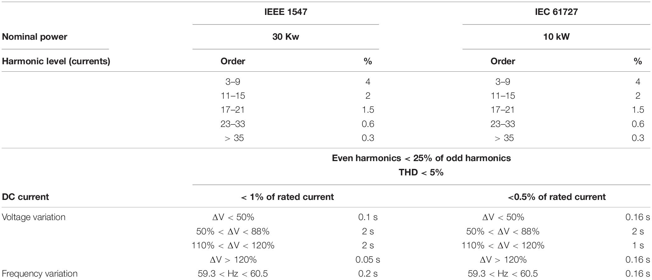
Table 1. Summary of the grid requirements concerning the IEEE 1547 and IEC 61727 standards.
Topologies of Five-Level Front-End Converters
In this section, a comprehensive review of the more recent topologies with a special focus on single-phase five-level inverters is provided. It should be noted that the anti-parallel diode of a controlled switch is considered a separate component, as is the case in normal applications.
A five-level three-phase inverter is proposed in Sajadian and Santos (2014), however, the three-phase system consists of three separate phases that can operate individually. In each phase, four fully controlled power switches and six diodes are needed. This topology is presented in Figure 1. A coupled inductor is needed for the topology. The output voltage of the converter can be calculated using (1). It should be noted that S1 operation is complementary to S2.
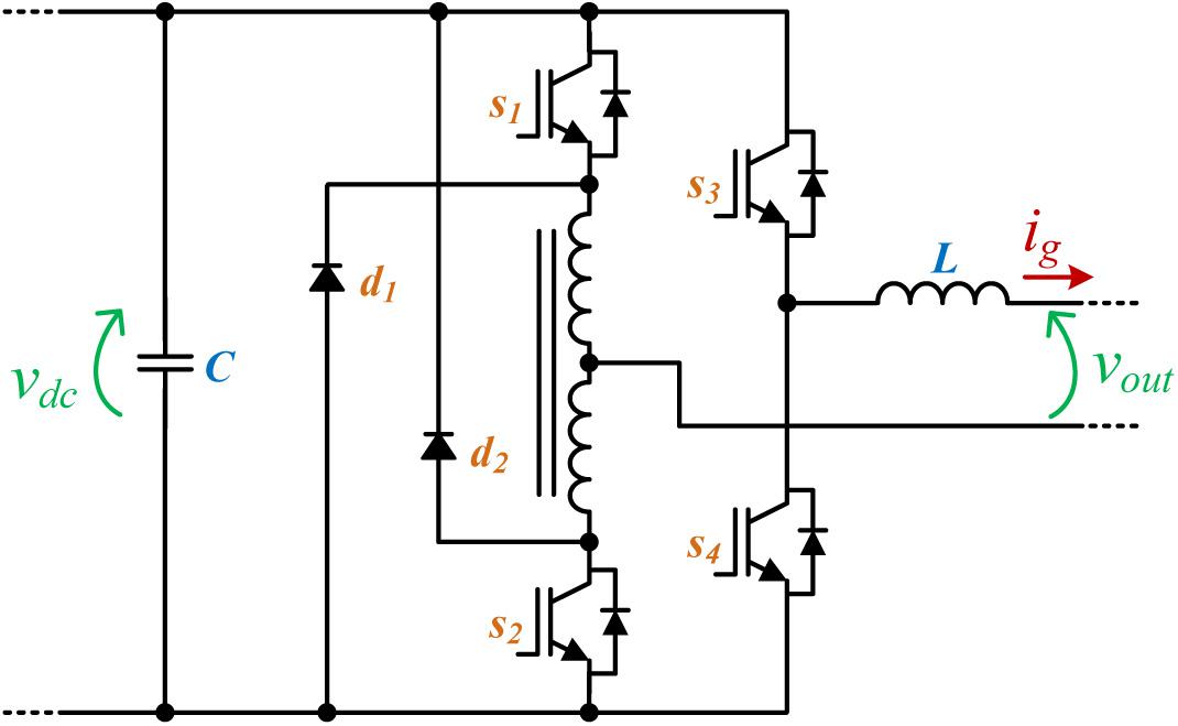
Figure 1. Topology proposed in Sajadian and Santos (2014).
The main advantage of this structure is that it requires fewer controlled switches and has no need for complex voltage-control algorithms for dc-link voltage-control algorithms as happens with many other topologies. The authors also claim that the topology improves power loss. However, a coupled inductor and certain operating conditions must be met.
In Korhonen et al. (2014), a five-level single-phase inverter based on neutral point and a flying capacitor is proposed that can produce ± vdc/2, ± vdc/4, and 0. As can be seen in Figure 2, it has eight fully controlled power switch and eight diodes. The output voltage of the converter can be calculated using (2). There are multiple alternatives for the ±vdc/4 that can be exploited to maintain the voltage of the floating capacitor within a tight boundary.
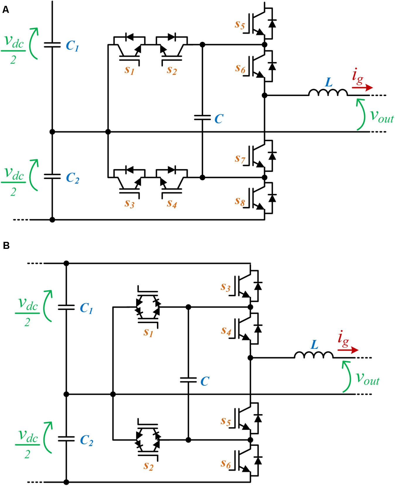
Figure 2. Topologies: (A) proposed in Korhonen et al. (2014); (B) proposed in Yuan (2014).
It should be noted that the switches and diodes need different voltage ratings, which can increase maintenance costs. Voltage fluctuation in the flying capacitor can affect output quality, as well as the split power source requirement, which can be limiting, and the utilized switches have different voltage ratings. Moreover, it can only produce half of the total dc-link voltage, which is not desirable. The authors compare the performance of the paper with a commercial NPC-5L topology, and the results show a very slight improvement in efficiency.
The authors in Yuan (2014) modify the structure proposed in Korhonen et al. (2014) and utilize reverse-blocking IGBTs. However, similar to the previous paper, it utilizes the redundant stages to balance the flying-capacitor voltage. The disadvantages are also similar. The authors claim that this topology requires a lower number of semiconductor count, because they are considering each of the reverse-blocking IGBTs as one semiconductor. However, a reverse-blocking IGBT is in effect composed of two back-to-back IGBTs that do not have any anti-parallel diode and this advantage is not very prominent. On the other hand, utilizing the reverse-blocking IGBTs, improves efficiency. Figure 2 shows the proposed topology.
The output voltage of the converter shown in Figure 2 can be calculated using (3). Comparing (3) with (2), it can be seen that they are essentially similar and the only difference is that (Yuan, 2014) (c.f. Figure 2) utilizes one bidirectional switch instead of two back-to-back unidirectional ones.
A three-phase five-level topology is proposed in Masaoud et al. (2014). It requires sixteen controlled switches and sixteen diodes. There are five voltage levels for each phase, 0, vdc/4, 2vdc/4, 3vdc/4, vdc, which, by considering a three-phase operation, would result in nine voltage levels. Although the topology has a relatively low number of switches per voltage levels for all the three-phases, it requires two different sources, where one of them should be a split-voltage source. This topology is presented in Figure 3. The output phase-voltage of the converter shown in Figure 3 can be calculated using (4).
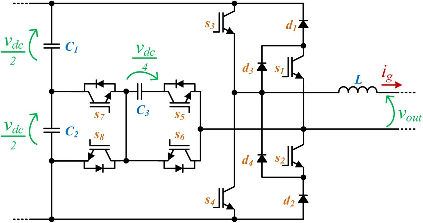
Figure 3. Topology proposed in Masaoud et al. (2014).
Authors in Vahedi et al. (2016) utilize a seven-level converter previously proposed by Kamal Al-Hadad called PUC to build a five-level converter with simplified control. This topology is presented in Figure 4. It is argued that the previously proposed seven-level converter has a very complex control and requires a high switching frequency as well as additional sensors. However, the simplified five-level converter changes the ratio V1 = 3V2 to V1 = 2V2 and also introduces a self-balancing algorithm to simplify the control. The output voltage levels are ± vdc/2 and ± vdc/4, 0, which achieve a unity voltage ratio between output and input voltage. The split power source being unnecessary is another advantage of such a system. The output phase voltage of the topology shown in Figure 4 can be calculated based on the switch states using (5).
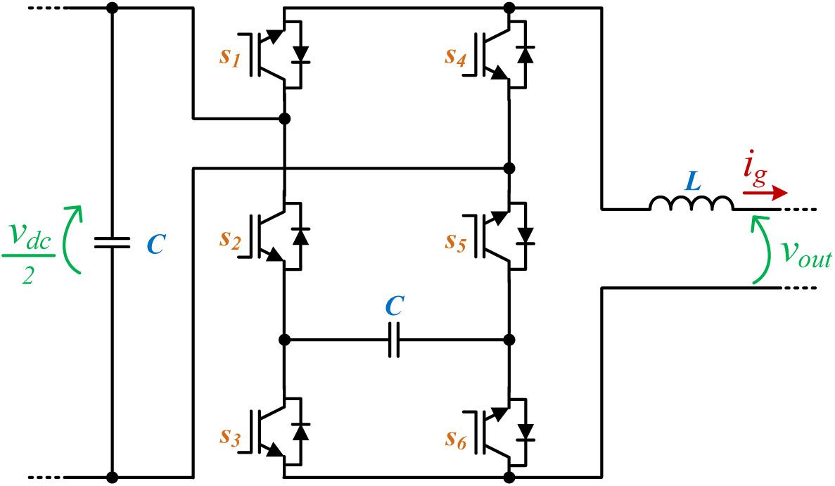
Figure 4. Topology proposed in Vahedi et al. (2016).
A single-phase five-level structure is proposed in Saeedian et al. (2018) based on the switching capacitor technique. Figure 5A shows the proposed structure, and the phase output voltage can be calculated using (6). Since the capacitors utilized in the topology can be easily balanced without needing any complex closed-loop control, one of the advantages of this system is a simple control. However, the most important benefit of the presented circuit is its voltage boosting capability. For an input source with a voltage vdc, it can produce a five-level ac output voltage with voltage levels of 0, ± vdc, and ± 2 vdc. For achieving this goal, one power supply, two capacitors, ten diodes, and seven power switches are required. This structure has a high number of active and passive components; however, one main advantage of this method is that it can produce an output twice the voltage level of the power supply.
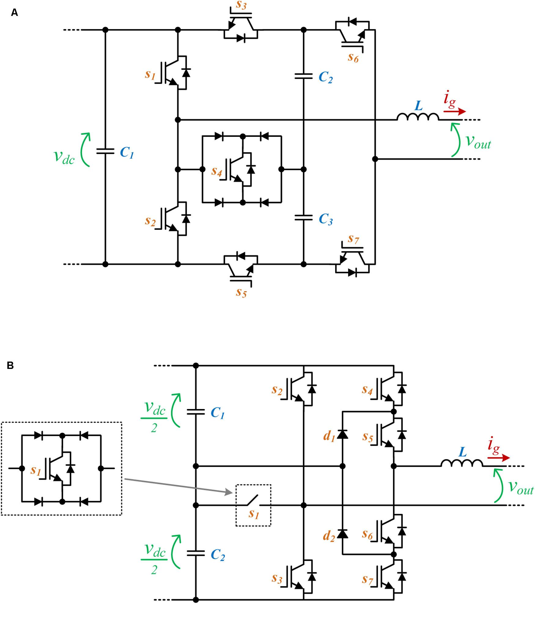
Figure 5. Topologies: (A) proposed in Saeedian et al. (2018); (B) proposed in Madhukar Rao and Sivakumar (2015).
In Madhukar Rao and Sivakumar (2015), a single-phase five-level inverter with fault tolerance is proposed. The proposed converter consists of seven power switches as well as twelve power diodes. A diode bridge in combination with a power switch in the output is utilized to cut off the fault current. However, the utilized diode bridge of the fault circuit breaker in the output can severely hinder the efficiency of the converter. Figure 5B shows the structure of the converter proposed in Madhukar Rao and Sivakumar (2015). The output voltage of the topology shown in Figure 5B can be calculated based on (7), while S1 can be used for interrupting the current path during faults.
A five-level inverter with a modular switched capacitor circuit is proposed in He and Cheng (2016). The main advantage of this topology is that the voltage levels can be increased by adding more switched capacitor bridge modules. As can be seen in Figure 6, the topology has twelve diode-switch sets for a five-level inverter. With each extra switched capacitor module, the output voltage amplitude can be increased to four times the input voltage vdc. The first two switch groups are defined by (8) and (9).
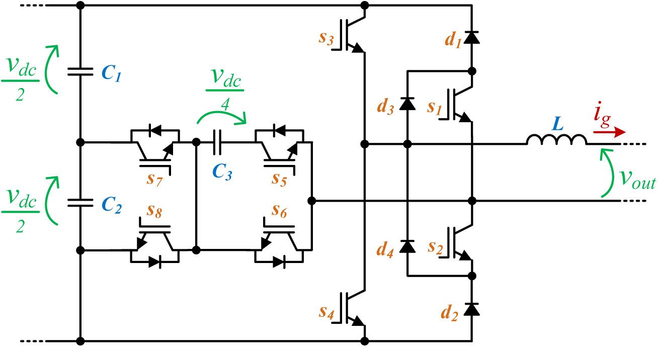
Figure 6. Topology proposed in He and Cheng (2016).
Considering the defined switching groups and the remaining switches, it is possible to calculate the output phase voltages, according to (10). It should be noted that the SP and SN are complementary.
Another five-level fault-tolerant structure is proposed in Gautam et al. (2017). This topology is presented in Figure 7. It consists of six IGBT-diode sets, as well as a bidirectional switch and an NPC leg. Compared to many other topologies with fault current limiting capability, this one has a moderate number of switches and capacitors. The required NPC can be considered one of the disadvantages of such topologies. Moreover, this topology can produce output voltages in the range of ± vdc. The output voltage levels based on the input source and the capacitor voltage can be calculated using (11). In the case of vc2 = vdc/2, there are five symmetrical voltage levels.
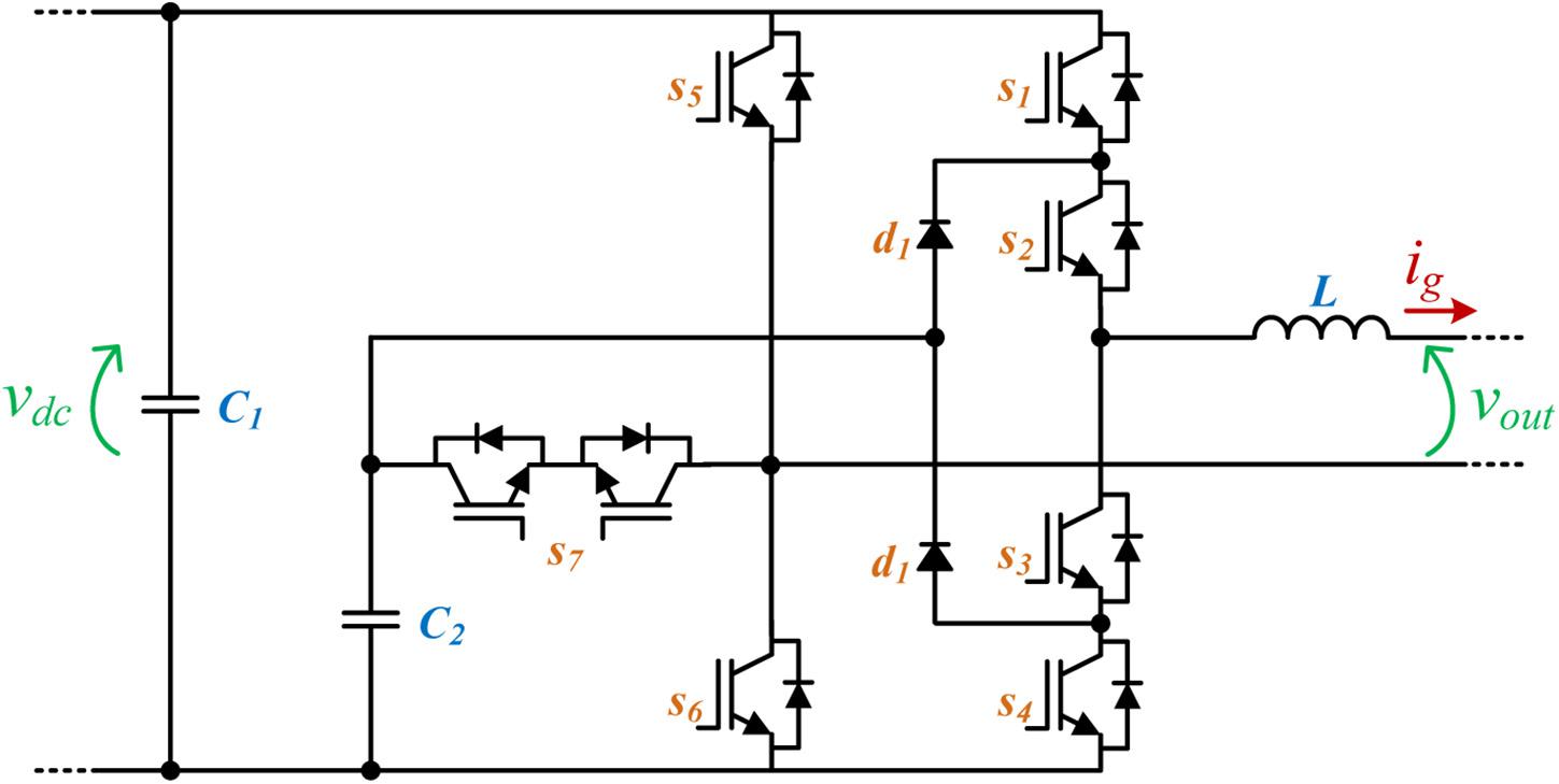
Figure 7. Topology proposed in Gautam et al. (2017).
A five-level inverter for medium-voltage applications is proposed in Narimani et al. (2016). Although the paper focuses on a three-phase structure, it can be easily utilized as a single-phase system too. The system includes eight switch-diode sets as well as two extra diodes for each phase. One of the disadvantages of such a topology is the requirement of a split-source supply and three additional capacitors. The output voltage levels include vdc/2, vdc/4, 0, −vdc/4, and −vdc/2. Figure 8A shows the abovementioned topology. Another disadvantage of this topology is a relatively complex balancing procedure for the three flying capacitors in each phase. Although the authors claim that the number of diodes is reduced compared to many previous topologies, the number of semiconductor devices is still relatively high. The output phase voltage of the topology shown in Figure 8A can be calculated based on the switch states using (12).
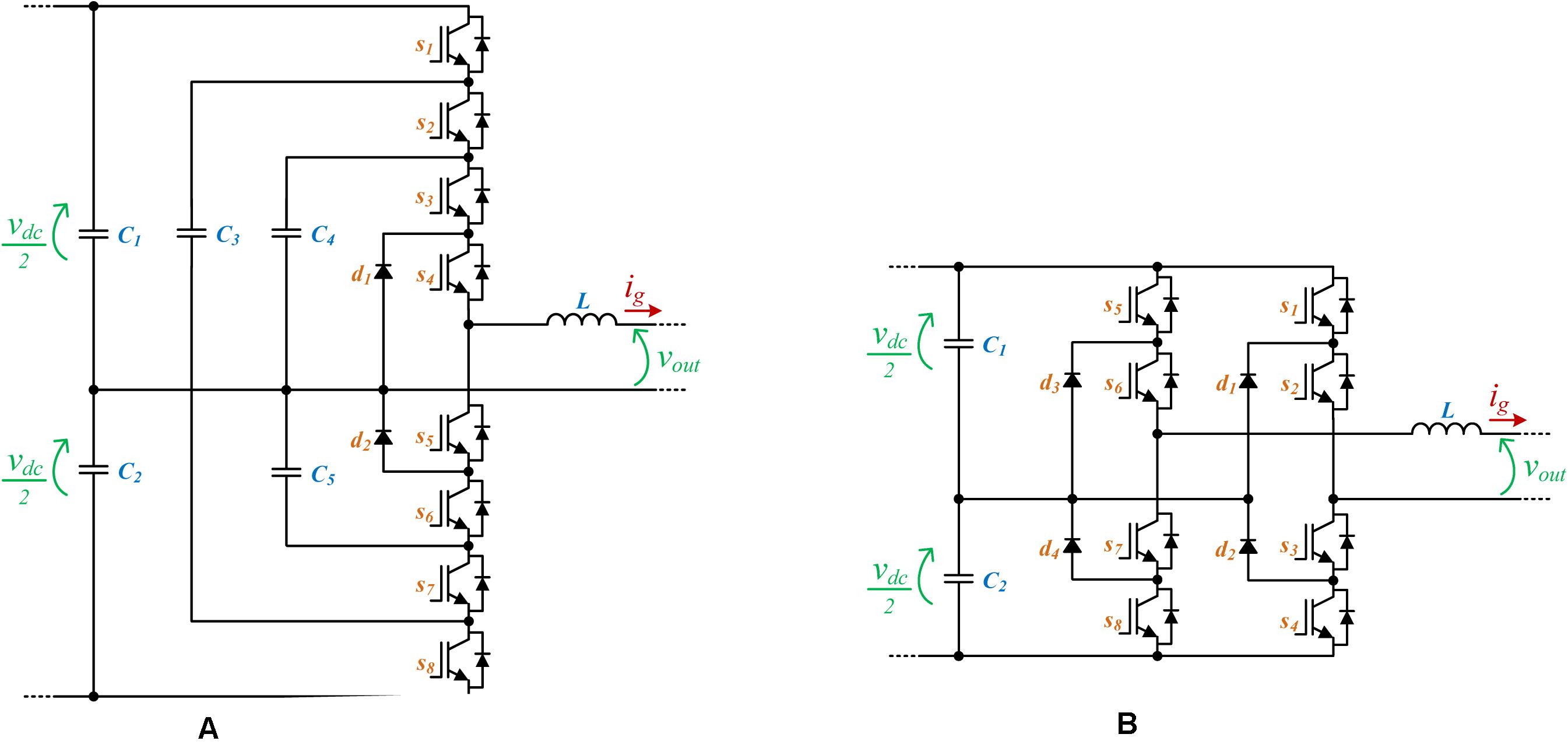
Figure 8. Topologies: (A) proposed in Narimani et al. (2016); (B) proposed in Aly et al. (2018).
Figure 8B depicts another five-level inverter based on a split-source supply (Aly et al., 2018). It requires fourteen switch-diode sets and four extra diodes. Although this topology requires a higher number of semiconductor devices compared to the topology proposed in Narimani et al. (2016), it has some other significant advantages including: simpler control, no flying capacitor, and fault-tolerant structure. The output voltages are −vdc, −vdc/2, 0, vdc/2, and vdc, which can be calculated using (13).
A bidirectional topology based on a half-bridge front-end structure and two flying-capacitor cascade structures is proposed in Naderi et al. (2015). This topology is shown in Figure 9. This topology has a split dc link and two flying capacitors, which represents the main disadvantage of this topology since it increases the control complexity. When compared with other topologies, this one requires a significant number of switching devices. Each of the flying capacitor cells is formed by four switching devices, which are responsible for producing three voltage levels. The output phase voltage of the topology shown in Figure 9 can be calculated based on the switch states defined in (14).
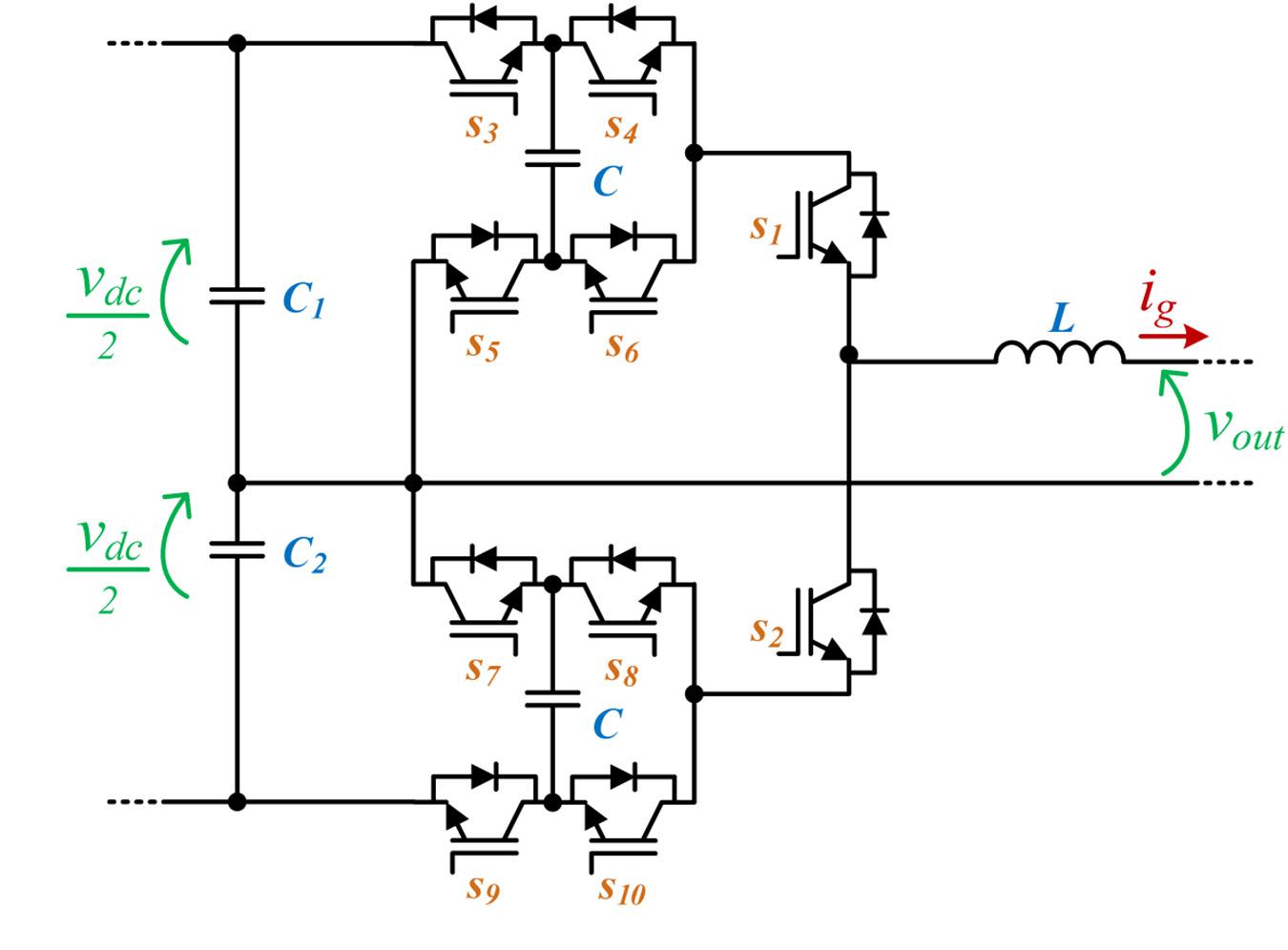
Figure 9. Topology proposed in Naderi et al. (2015).
In this case, the following switches work in a complementary manner.
A bidirectional topology based on a full-bridge front-end structure and a bidirectional-bipolar cell connected between the neutral wire and a split dc link is presented in Monteiro et al. (2016). This topology is presented in Figure 10A. The full-bridge structure is responsible for obtaining three voltage levels (+ vdc, 0, −vdc), while the bidirectional-bipolar cell is responsible for obtaining the other two voltage levels (+ vdc/2, −vdc/2). The output phase voltage can be calculated using (16). In order to optimize the efficiency, the switching devices S1 and S2 can be switched at a low frequency (i.e., the frequency of the power grid voltage), while the other switching devices are switched at high frequency.
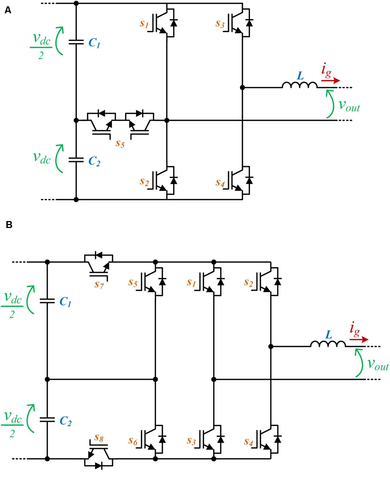
Figure 10. Topologies: (A) proposed in Monteiro et al. (2016); (B) proposed in Leite et al. (2018).
A bidirectional topology based on a full-bridge front-end structure and a back-end dc–dc structure with a split dc link is presented in Leite et al. (2018). This topology, shown in Figure 10B, operates with five voltage levels, according to the operation of the back-end dc–dc converter. The switching devices s1 and s2 are switched at a low frequency (i.e., the frequency of the power grid voltage), while the other switching devices are switched at high frequency. As claimed in the paper, this is an import aspect since it is possible to optimize the operation of the converter, reducing the switching losses. The output phase voltage of the topology shown in Figure 10B can be calculated based on the switch states using (17).
Modular multilevel converters (MMCs) are another type of circuit that can realize five-level output voltage (Wang et al., 2019; Xu et al., 2019). In a way, MMCs are an extension of the earlier multilevel circuits based on the flying capacitors, with the exception that MMCs are much more feasible in higher voltage levels (Dekka et al., 2017). Theoretically, there is no limit to the number of voltage levels that an MMC can achieve, but the practical considerations such as controller complexity and cost would limit the number of voltage levels. Since the main advantage of the MMC topologies is in higher voltage and higher voltage levels, here only two of the more basic topologies that utilize half-bridge and full-bridge submodules are considered that are shown in Figures 11–C. The output voltage of the submodules shown in Figures 11A–C can be calculated using (18), (19), and (20), respectively.
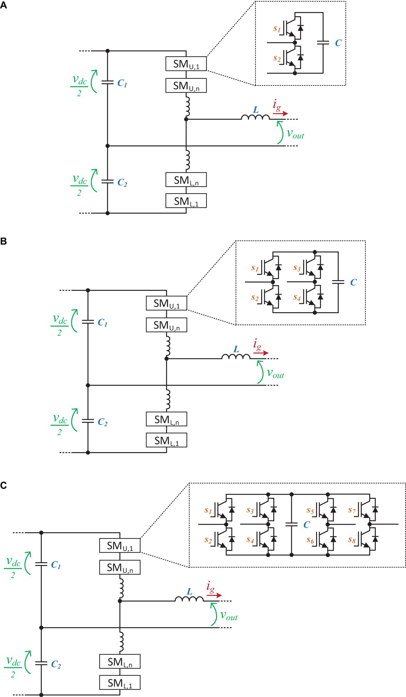
Figure 11. MMC topologies: (A) proposed in Zhou et al. (2018); (B) proposed in Hu et al. (2018); (C) proposed in Goetz et al. (2015).
In Zhou et al. (2018), each MMC submodule has a half-bridge structure requiring two switches and two diodes. With the structure proposed in Zhou et al. (2018), eight switch-diode sets, two inductors, and four capacitors are required (Xu et al., 2018). However, it is possible to reduce the number of required modules to half, if the switching technique in Hu and Jiang (2014) is utilized. Based on the control technique proposed in Hu and Jiang (2014), four switch-diode sets, two inductors, and four capacitors are required. On the other hand, the size of the required inductor increases. The structure proposed in Hu et al. (2018) requires double switch-diode sets, than the one proposed in Zhou et al. (2018); however, because of the control proposed in Hu et al. (2018), smaller capacitors can be used while at the same time increase the output to input voltage ratio to around 0.7vdc. Another advantage of these MMCs is better fault tolerance.
There are other MMC topologies that focus on additional features such as sensorless balancing and/or parallel connection (Xu et al., 2018; Jin et al., 2019; Li et al., 2019; Xu et al., 2019). As an example, an extra half-bridge is introduced in Goetz et al. (2015, 2016) that brings about the capability to connect neighboring modules in parallel. The parallel connection decreases string impedance, reduces current ripple, and improves the balancing capability of the capacitors. The parallel connection of modules distributes load current among multiple capacitors (Zhu et al., 2018) and reduces requirements on the current rating of the switches to one half. Sizing the switches to lower current ratings compensates double the number of discrete switches of the MMCSP, and the amount of silicon needed is comparable to the MMC topology in Hu et al. (2018). The control method proposed in Li et al. (2017) reduces the complexity of the control algorithm to the level of standard MMCs. Large voltage differences and temporal imbalance might cause inrush currents between paralleled modules and reduce the feasibility of the parallel mode. Means to overcome the inrush currents are presented in Li et al. (2019).
Modulation Techniques for Five-Level Front-End Converters
One distinguishing aspect of the multilevel converters, when compared to the traditional two-level converters, is the wide variety of usable modulation techniques. Multilevel converters require different modulation techniques in order to synthesize all of its possible voltage levels, regardless of being three-level, five-level, or higher-level converters. Moreover, different modulation techniques can be applied to the same converter, as is the case of the most traditional techniques, but some techniques are only feasible to specific converters, as is the case of techniques that are specially developed for a given converter in order to optimize, for instance, the switching losses.
In a voltage-source inverter, the modulation technique is responsible for transforming a given reference voltage into a set of defined states of the switching devices comprising the converter, so that the desired reference voltage or current, depending on the used feedback control, is produced at its ac side. The two most common groups of modulation techniques for voltage-source inverters, regardless of the number of voltage levels, are the pulse-width modulation (PWM) and the space vector modulation (SVM). However, these two groups of modulation techniques must be properly adopted when applied to multilevel converters.
Pulse-Width Modulation (PWM)
PWM is a modulation technique widely used in two-level and three-level inverters, where a single triangular carrier and one (in two-level inverters) or two (in three-level inverters) reference voltages are used. The popularity of this technique is due to its ease of implementation, especially regarding digital signal processor (DSP)-based control systems, and due to the establishment of a fixed switching frequency, which is useful for sizing the output passive filters of the converter. Besides, since most inverters contain complementary pairs of active switches, one triangular carrier can be used to generate a pair of complementary signals for the switches. However, in multilevel converters, it is mandatory to use either more than one triangular carrier or more than two reference voltages in order to obtain the total number of possible voltage levels.
The classical multilevel PWM techniques consist of increasing the number of triangular carriers, which are either vertically or horizontally distributed, and the number of triangular carriers must be n-1, where n is the number of voltage levels. For the specific case of this paper, i.e., five-level inverters, four triangular carriers and one reference voltage should be used in order to attain a five-level operation with a classical multilevel PWM technique. Besides, taking into consideration the triangular carrier disposition, two main schemes can be feasible, i.e., with vertical disposition and horizontal disposition. In a vertical disposition-based PWM, all the carriers have the same amplitude and frequency but different average values, so that the maximum value of a given carrier coincides with the minimum value of the upper one, and so on. In this case, two of the carriers are only positive and the other two are only negative. In terms of phase, there are three main approaches regarding vertical-disposition PWM schemes: (a) phase disposition, where all the carriers have the same phase (Figure 12A); (b) phase opposition, where the positive carriers are 180° phase shifted with the negative carriers (Figure 12B); (c) alternative phase opposition, where the consecutive carriers are 180° phase shifted from each other (Figure 12C). Vertical disposition is suitable for topologies comprising a split dc link, such as NPC and flying capacitor, but can lead to power unbalances in topologies with independent dc links. Regarding horizontal distribution, this scheme is also termed as phase-shifted PWM, where all the carriers have the same amplitude, average value, and frequency but different phase angles. The phase shift between consecutive carriers should be equal to 360°/n, where n is the number of triangular carriers. Hence, in this case, each triangular carrier is 90° phase shifted from each other, as can be seen in Figure 12D. Another possibility is to use two reference voltages 180° phase shifted between each other (as in a unipolar PWM scheme) and only two triangular carriers obeying to a 180°/n ratio. In this case, the carriers are not evenly divided in one switching period due to the additional reference voltage, which emulates the two removed carriers, as can be seen in Figure 12E. Horizontal-disposition schemes have the advantage of multiplying the switching frequency (the frequency of each carrier) into the output frequency by a factor of n, (four, in this case), similarly to an interleaved converter. Compared to vertical disposition, this scheme allows a balanced power distribution in topologies such as cascaded multilevel and a natural voltage balancing in the flying-capacitor topology. Nevertheless, vertical-distribution schemes allow a lower THD in the output voltage than the horizontal distribution for the same characteristics of operation (Rodriguez et al., 2002, 2007; Kouro et al., 2010; Malinowski et al., 2010; Debnath et al., 2015; Li et al., 2015).
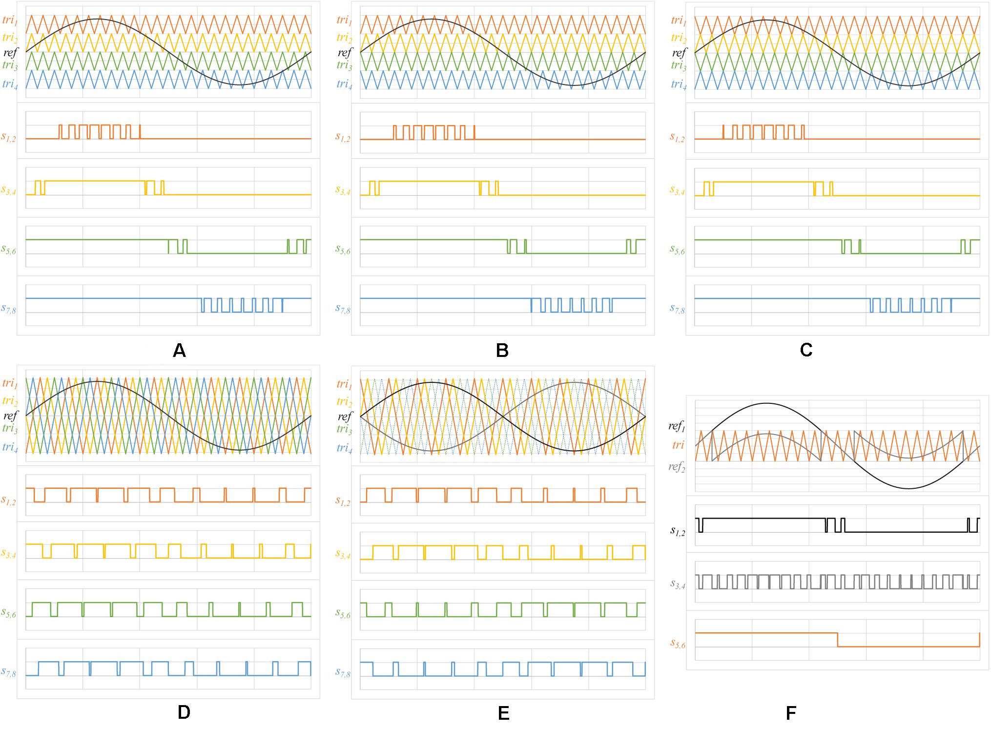
Figure 12. Pulse-width modulation: (A) vertical phase disposition PWM carriers for five-level inverters; (B) vertical phase opposition PWM carriers for five-level inverters; (C) vertical alternative phase disposition PWM carriers for five-level inverters; (D) horizontal disposition PWM carriers for five-level inverters using based on four carriers and one reference voltage; (E) horizontal disposition PWM carriers for five-level inverters based on two carriers and two reference voltages; (F) horizontal-disposition PWM carriers for five-level inverters using a single carrier and a modified reference voltage.
However, depending on the available resources, the use of multiple triangular carriers can also be an obstacle. One method to suppress this is to use a single triangular carrier but different reference voltages, also called modified reference voltages. Therefore, each complementary pair of signals for the active switches is achieved not from each triangular carrier but from each reference voltage. This approach can also be used to optimize the switching frequency of a multilevel converter. For instance, in Leite et al. (2018), a modulation strategy is implemented that allows an active switch pair to operate with a switching frequency equal to the low-frequency component of the output voltage, i.e., the power grid frequency. This allows reducing the switching losses of the converter or, even further, to apply a different type of power semiconductor that does not need to be fully controlled (e.g., thyristor), offering lower conduction losses and a lower cost. Figure 12F shows an example of this modulation scheme, where one carrier and two references can be seen, generating three pairs of switch signals.
Space Vector Modulation (SVM)
While the PWM techniques are based on the modulation of each complementary pair of active switches, the SVM technique consists of acting upon the converter as a whole. This means that, in each instant, the state of all the active switches comprising the converter is determined in order to satisfy a given reference voltage. This is achieved via a coordinate transformation from a-b-c to α-β, where the reference frame is divided into sectors that contain a given output voltage. In order to synthesize the desired voltage (which is contained in a given sector), two adjacent voltage vectors (which are produced by a given converter state) should be used, with the length of each one being proportional to the on-time of each converter state. Compared to PWM, SVM also allows a fixed switching frequency but reduces the total number of commutations of a given switch in each output cycle, since each switch state can be assigned in a way that avoids redundant switching. A similar strategy, called pulse decoding, can be seen in Ge and Fang (2008), where only one switch pair switches at high frequency. Moreover, SVM allows a better utilization of the dc-link voltage, since it inherently comprises a third harmonic injection that allows achieving an output voltage 15% higher than PWM for the same dc-link voltage and modulation index. Due to this reason, SVM is an interesting modulation technique to be applied in three-phase inverters for three-wire systems, as is the case of traction applications, for instance (Kanchan et al., 2005; Vinod et al., 2018). The main disadvantage of SVM compared to PWM is its complexity, requiring calculations that do not exist in PWM.
In multilevel converters, SVM is attainable through a higher number of sectors, as well as a higher number of voltage vectors. While three-phase two-level converters allow six non-null voltage vectors and six sectors, as can be seen in Figure 13A, three-phase five-level converters allow sixty non-null and non-redundant voltage vectors, comprising a total of ninety-six sectors, as represented in Figure 13B. Each triangle represents a sector, while each triangle vertex represents one voltage vector. The number of voltage vectors depends on the nature of the converter, i.e., whether it allows redundant states (multiple voltage vectors to produce the same output voltage) or not (only one voltage vector to produce a given output voltage) (Dae-Wook et al., 2003; Ahmed et al., 2016; Li et al., 2017). SVM is advantageous over PWM when the number of levels is very high, i.e., when controlling the converter as a whole is simpler to implement instead of controlling each complementary switch pair.
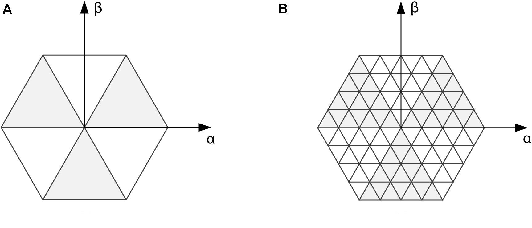
Figure 13. Space vector representation for three-phase inverters: (A) two-level; (B) five-level.
Comparison Between Topologies
This section presents a comparison regarding the topologies identified in section “Topologies of Five-Level Front-End Converters.” The comparison was performed considering three main categories: with flying capacitor, without flying capacitors, and MMCs. For all the topologies, the key parameters were considered. Table 2 shows the comparison between the topologies. Analyzing this table in more detail, the MMC topologies (Goetz et al., 2015, 2016) requires more devices (diodes and switching devices), which can be identified as a disadvantage since it can increase the conduction and switching losses, contributing to a reduction in efficiency. Besides the MMC topologies, the topology (Masaoud et al., 2014) requires two sources and is the only topology with this requisite, which can be impeditive for applications as renewables since two independent sources are required. The topology (Sajadian and Santos, 2014) requires the use of a transformer, which can be a disadvantage, but it only requires a single source and no capacitors for obtaining the five voltage levels. Topologies (Sajadian and Santos, 2014; He and Cheng, 2016; Vahedi et al., 2016; Gautam et al., 2017; Saeedian et al., 2018) require a single dc link, i.e., a split dc link is not necessary for the operation with five levels; therefore, for applications as renewables, this is an interesting aspect. Since fault tolerance and reliability issues are not the main focus of this review, only a few examples of the more recent topologies (Madhukar Rao and Sivakumar, 2015; Gautam et al., 2017; Hu et al., 2018) were considered. Considering the fault-tolerant topologies, it is clear that higher tolerance to fault comes at the cost of a significantly higher number of active components.
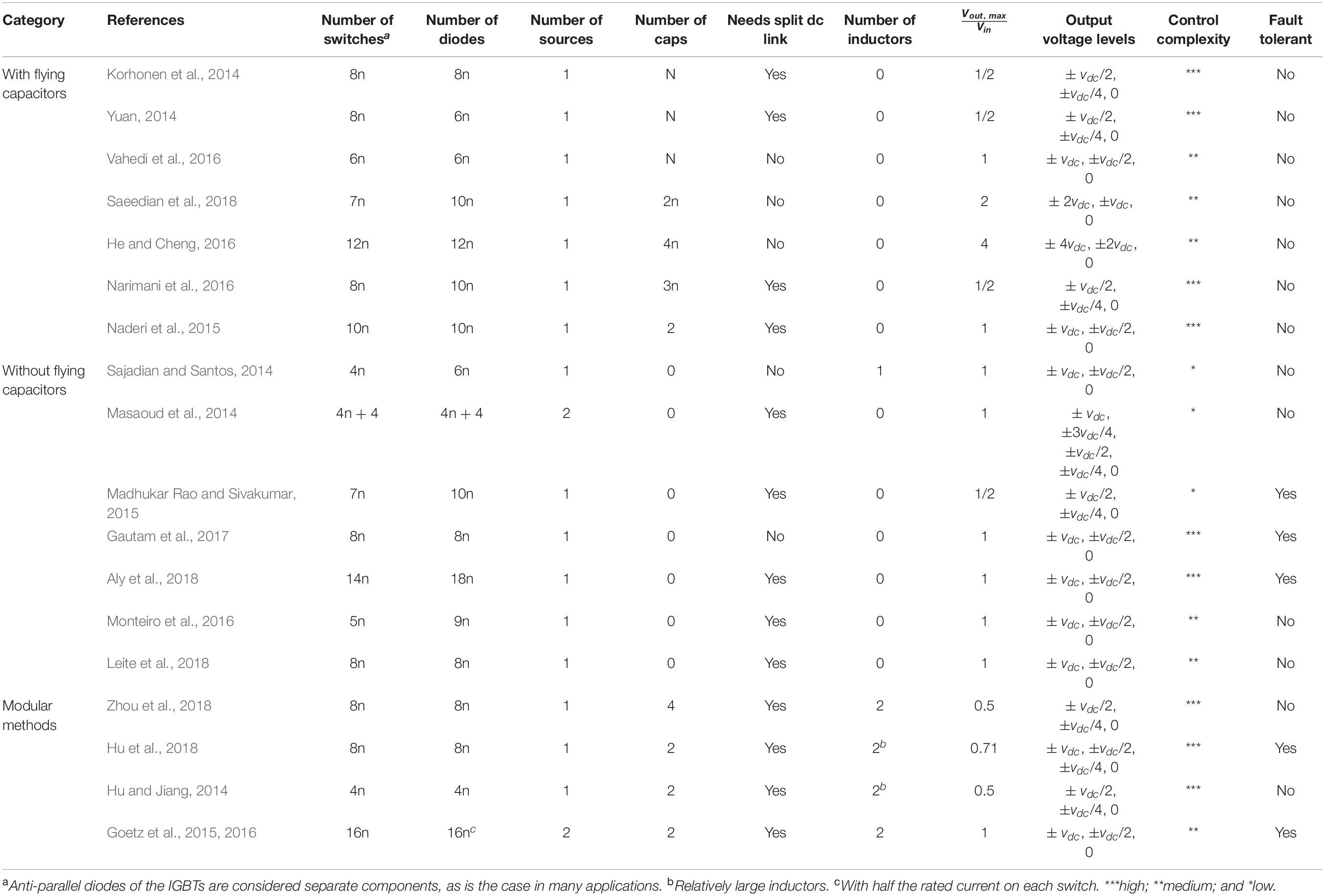
Table 2. Comparison between the presented topologies.
The main problem in the methods based on the flying capacitors is the control complexity. When the capacitor voltage is a fraction of the supply voltage, then the controller should monitor the voltage of that capacitor and actively maintain it in a tight boundary. On the other hand, the methods based on the multiple/split sources are more expensive to implement in the end, since they require either separate power sources or keeping the split-source voltage considering all the inherent differences in the system. The capacitors of the split dc link may exhibit a difference in voltage sharing, causing a voltage ripple in the dc link. Consequently, the stabilization of the voltage ripple may require a considerably large dc-link capacitor. In addition, any imbalance in the load causes a neutral current, which causes a perturbation in the split dc-link voltage (Jasna and Anitha, 2014). Consequently, balancing the split dc-link capacitors is the subject of a proper control. Therefore, as happens always in engineering applications, here a trade-off should be maintained on the control complexity, sensor requirements, fault tolerance, and cost. Regarding the topologies based on modular structures, only a few of them are present, since the main advantage of such methods is framed in higher voltage levels. Therefore, as a five-level converter, modular multilevel methods are not very economical.
Regarding the number of semiconductors, it is commonly known that a higher number of passive semiconductors contribute to a decrease in the cost and the control complexity of the inverter but negatively affect its efficiency (Graditi et al., 2011). Consequently, the additional production of heat contributes to an increase in the requirements on system cooling, as well as to an acceleration in the aging of semiconductors (Reynolds, 1974). In this context, higher efficiency is generally achieved by trading the number of passive semiconductors (e.g., diodes) and active semiconductors (e.g., MOSFETs and IGBTs) (Kyono, 2006). Naturally, a higher overall number of components in the inverter, both passive and active, lowers its reliability, if the components do not introduce fault-tolerance itself (Zhang et al., 2014).
Conclusion
Worldwide, distributed renewable-energy resources are seen as absolutely fundamental to accomplish with the target to minimize environmental concerns, to obtain access to affordable energy, and to contribute to a sustainable power grid. Over the past few decades, in order to enable the increasingly effective integration of renewable-energy sources, power electronics technologies have played a leading role. In fact, even today, power electronics technologies are seen as one of the fundamental challenges for the widespread use of renewable-energy sources. Embracing this context, this paper presents a review of power electronics converters that can be used for interfacing renewable-energy sources into the power grid, concentrating on front-end converters with a voltage-source structure. More specifically, in a more attractive future perspective, this review is only focused on five-level structures. Thus, throughout the paper, the most relevant five-level topologies for the contextualization of renewable-energy sources in smart grids are presented. As a result, an effective comparison between the topologies is presented, highlighting key aspects that are useful to select a topology in detriment of others, according to the number of passive and active semiconductors, sources, capacitors, split dc links, inductors, and voltage levels. As an example, based on the established comparison, it is possible to conclude that topologies with more than one source are not advantageous and, on the other hand, topologies with a single dc link represent an interesting aspect for renewable-energy source applications. Based on the established comparison, it is possible to conclude that topologies with more than one source are not advantageous and, on the other hand, topologies with a single dc link represent an interesting aspect for renewable-energy source applications. The comparison also shows that topologies with a flying capacitor are not ideal concerning fault-tolerant characteristics, and a topology that accomplishes with the combined criteria such as being fault-tolerant, flying capacitors being unnecessary, and with reduced control complexity, which are three relevant features for obtaining reliable and high-efficiency converters to interface renewable-energy sources with the power grid, was identified. The topologies that require lower control complexity are all based on structures independent of flying capacitors, which is understandable, since such capacitors require a dedicated control loop. Moreover, such topologies require additional hardware, such as sensors and signal conditioning circuits. On the other hand, the topologies based on modular structures require more control complexity, since these structures are based on submodules (i.e., constituted by half-bridge or full-bridge converters). Notwithstanding, it is important to emphasize that the objective of this paper is not directly related to the identification of a specific topology that complies with all the benefits under study; it has the goal of presenting the different advantages and disadvantages of each topology in order to facilitate the comparison of such topologies for different purposes.
Author Contributions
VM, NT, TS, and TK contributed to writing the manuscript. JA and SG contributed to review the manuscript and to present suggestions and corrections. All authors contributed to the article and approved the submitted version.
Conflict of Interest
The authors declare that the research was conducted in the absence of any commercial or financial relationships that could be construed as a potential conflict of interest.
Acknowledgments
This work has been supported by FCT – Fundação para a Ciência e Tecnologia with-in the Project Scope: UIDB/00319/2020. This work has been supported by the FCT Project newERA4GRIDs PTDC/EEIEEE/30283/2017, and by the FCT Project DAIPESEV PTDC/EEI-EEE/30382/2017. TS was supported by the doctoral scholarship SFRH/BD/134353/2017 granted by FCT.
References
Ahmed, B., Aganah, K. A., Ndoye, M., Arif, M. A., Luciano, C., and Murphy, G. V. (2017). “Single-phase cascaded multilevel inverter topology for distributed DC sources,” in 2017 IEEE 8th Annual Ubiquitous Computing. Electronics and Mobile Communication Conference (UEMCON), Vol, 19-21, New York, NY, 514–519.
Ahmed, I., Borghate, V. B., Matsa, A., Meshram, P. M., Suryawanshi, H. M., and Chaudhari, M. A. (2016). Simplified space vector modulation techniques for multilevel inverters. IEEE Trans. Power Electron. 31, 8483–8499. doi: 10.1109/TPEL.2016.2520078
Aly, M., Ahmed, E. M., and Shoyama, M. (2018). A new single-phase five-level inverter topology for single and multiple switches fault tolerance. IEEE Trans. Power Electron. 33, 9198–9208. doi: 10.1109/TPEL.2018.2792146
Araiza, J., Hambrick, J., Moon, J., Starke, M., and Vartanian, C. (2018). “Grid energy-storage projects: engineers building and using knowledge in emerging projects,” in IEEE Electrification Magazine Vol, 6, Piscataway, NJ: IEEE, 14–19. doi: 10.1109/mele.2018.2849842
Baxter, R., Gyuk, I., Byrne, R. H., and Chalamala, B. R. (2018). “Engineering Energy-storage projects: applications and financial aspects,”in IEEE Electrification Magazine Vol, 6, Piscataway, NJ: IEEE, 4–12. doi: 10.1109/mele.2018.2849834
Boicea, V. A. (2014). Energy storage technologies: the past and the present. Proc. IEEE 102, 1777–1794. doi: 10.1109/jproc.2014.2359545
Bollen, M., Zhong, J., Zavoda, F., Meyer, J., McEachern, A., and Lopez, F. C. (2010). “Power quality aspects of smart grids,” in EPRI PQ and Smart Distribution. Conference and Exhebition. 14/06/2010-17/06/2010.
Ceaki, O., Seritan, G., Vatu, R., and Mancasi, M. (2017). “Analysis of power quality improvement in smart grids,” in 2017 10th International Symposium on Advanced Topics in Electrical Engineering (ATEE), Piscataway, NJ: IEEE, 797–801.
Dae-Wook, K., Yo-Han, L., Bum-Seok, S., Chang-Ho, C., and Dong-Seok, H. (2003). An improved carrier-based SVPWM method using leg voltage redundancies in generalized cascaded multilevel inverter topology. IEEE Trans. Power Electron. 18, 180–187. doi: 10.1109/TPEL.2002.807187
Debnath, S., Qin, J., Bahrani, B., Saeedifard, M., and Barbosa, P. (2015). Operation control and applications of the modular multilevel converter: a review. IEEE Trans. Power Electron. 30, 37–53. doi: 10.1109/tpel.2014.2309937
Dekka, A., Wu, B., Fuentes, R. L., Perez, M., and Zargari, N. R. (2017). Evolution of topologies, modeling, control schemes, and applications of modular multilevel converters. IEEE J. Emerg. Select. Top. Power Electron. 5, 1631–1656. doi: 10.1109/JESTPE.2017.2742938
Faisal, M., Hannan, M. A., Ker, P. J., Hussain, A., Mansor, M. B., and Blaabjerg, F. (2018). Review of energy storage system technologies in microgrid applications: issues and challenges. IEEE Access. 6, 35143–35164. doi: 10.1109/access.2018.2841407
Gautam, S. P., Kumar, L., Gupta, S., and Agrawal, N. (2017). A single-phase five-level inverter topology with switch fault-tolerance capabilities. IEEE Trans. Ind. Electron. 64, 2004–2014. doi: 10.1109/TIE.2016.2626368
Ge, B., and Fang, P. (2008). “An effective control technique for medium-voltage high power induction motor drives,” in 2008 34th Annual Conference of IEEE Industrial Electronics, Vol. 10-13, Orlando, FL, 3195–3200.
Goetz, S. M., Li, Z., Liang, X., Zhang, C., Lukic, S. M., and Peterchev, A. V. (2016). Control of modular multilevel converter with parallel connectivity—Application to battery systems. IEEE Trans. Power Electron. 32, 8381–8392. doi: 10.1109/tpel.2016.2645884
Goetz, S. M., Peterchev, A. V., and Weyh, T. (2015). Modular multilevel converter with series and parallel module connectivity: topology and control. IEEE Trans. Power Electron. 30, 203–215. doi: 10.1109/TPEL.2014.2310225
Graditi, G., Adinolfi, G., Femia, N., and Vitelli, M. (2011). “Comparative analysis of synchronous rectification boost and diode rectification boost converter for DMPPT applications,” in 2011 IEEE International Symposium on Industrial Electronics, Piscataway, NJ: IEEE, 1000–1005.
Gupta, K. K., Ranjan, A., Bhatnagar, P., Sahu, L. K., and Jain, S. (2015). Multilevel inverter topologies with reduced device count: a review. IEEE Tran. Power Electron. 31, 135–151. doi: 10.1109/tpel.2015.2405012
He, L., and Cheng, C. (2016). A flying-capacitor-clamped five-level inverter based on bridge modular switched-capacitor topology. IEEE Trans. Ind. Electron. 63, 7814–7822. doi: 10.1109/TIE.2016.2607155
Hester, S. (2002). “IEEE 929–2000 recommended practice for utility interface of photovoltaic(PV) systems,” in Workshop Proceedings-Solar Electric Power Association, Piscataway, NJ: IEEE.
Hu, J., Xiang, M., Lin, L., Lu, M., Zhu, J., and He, Z. (2018). Improved design and control of FBSM MMC with boosted AC voltage and reduced DC capacitance. IEEE Trans. Ind. Electron. 65, 1919–1930. doi: 10.1109/TIE.2017.2739679
Hu, P., and Jiang, D. (2014). A level-increased nearest level modulation method for modular multilevel converters. IEEE Trans. Power Electron. 30, 1836–1842. doi: 10.1109/tpel.2014.2325875
Jasna, M. A., and Anitha, P. (2014). Mitigation of V oltage Imbalance in the DC link of a Split Link Four Wire Inverter.
Jin, Y., Xiao, Q., Dong, C., Jia, H., Mu, Y., Xie, B., et al. (2019). A novel submodule voltage balancing scheme for modular multilevel cascade converter—double-star chopper-Cells (MMCC-DSCC) based STATCOM. IEEE Access. 7, 83058–83073. doi: 10.1109/access.2019.2924609
Kanchan, R. S., Baiju, M. R., Mohapatra, K. K., Ouseph, P. P., and Gopakumar, K. (2005). Space vector PWM signal generation for multilevel inverters using only the sampled amplitudes of reference phase voltages. IEEE Pro. Electric Power Appl. 152, 297–309. doi: 10.1049/ip-epa:20045047
Karwatzki, D., and Mertens, A. (2018). Generalized control approach for a class of modular multilevel converter topologies. IEEE Trans. Power Electron. 33, 2888–2900. doi: 10.1109/TPEL.2017.2703917
Korhonen, J., Sankala, A., Ström, J., Silventoinen, P., and Doktar, A. (2014). “Five-level inverter with a neutral point connection and a flying capacitor,” in 2014 16th European Conference on Power Electronics and Applications, Vol. 26-28, Lappeenranta, 1–7.
Kouro, S., Malinowski, K., Gopakumar, J., Pou, L. G., Franquelo, B., Wu, J., et al. (2010). Recent advances and industrial applications of multilevel converters. IEEE Trans. Ind. Electron. 57, 2553–2580. doi: 10.1109/TIE.2010.2049719
Kyono, Y. (2006). Switching-mode power supply having a synchronous rectifier, US7120036B2 United States Patent.
Leite, R. S., Afonso, J. L., and Monteiro, V. (2018). A novel multilevel bidirectional topology for on-board EV battery chargers in smart grids. Energies 11:3453. doi: 10.3390/en11123453
Li, W., Hu, J., Hu, S., Yang, H., Yang, H., and He, X. (2017). Capacitor voltage balance control of five-level modular composited converter with hybrid space vector modulation. IEEE Trans. Power Electron. 33, 5629–5640. doi: 10.1109/tpel.2017.2740960
Li, Y., Wang, Y., and Li, B. Q. (2015). Generalized theory of phase-shifted carrier PWM for cascaded H-bridge converters and modular multilevel converters. IEEE J. Emerg. Select. Top. Power Electron. 4, 589–605. doi: 10.1109/jestpe.2015.2476699
Li, Z., Lizana, R., Peterchev, A. V., and Goetz, S. M. (2017). “Distributed balancing control for modular multilevel series/parallel converter with capability of sensorless operation,” in 2017 IEEE Energy Conversion Congress and Exposition (ECCE), Cincinnati, OH, 1787–1793.
Li, Z., Ricardo Lizana, F., Sha, S., Yu, Z., Peterchev, A. V., and Goetz, S. M. (2019). Module implementation and modulation strategy for sensorless balancing in modular multilevel converters. IEEE Trans. Power Electron. 34, 8405–8416. doi: 10.1109/TPEL.2018.2886147
Lopez-Martin, V. M., Azcondo, F. J., and Pigazo, A. (2018). Power quality enhancement in residential smart grids through power factor correction stages. IEEE Trans. Ind. Electron. 65, 8553–8564. doi: 10.1109/tie.2018.2813965
Madhukar Rao, A., and Sivakumar, K. (2015). A fault-tolerant single-phase five-level inverter for grid-independent PV systems. IEEE Trans. Ind. Electron. 62, 7569–7577. doi: 10.1109/TIE.2015.2455523
Malinowski, M., Gopakumar, K., Rodriguez, J., and Pérez, M. A. (2010). A survey on cascaded multilevel inverters. IEEE Trans. Ind. Electron. 57, 2197–2206. doi: 10.1109/TIE.2009.2030767
Masaoud, A., Ping, H. W., Mekhilef, S., and Taallah, A. (2014). Novel configuration for multilevel DC-link three-phase five-level inverter. IET Power Electron. 7, 3052–3061. doi: 10.1049/iet-pel.2013.0812
Mazumder, S. K. (2019). Energy storage: a power electronics system view. IEEE Power Electron. Mag. 6, 36–38. doi: 10.1109/mpel.2019.2947984
Molina, M. G. (2017). Energy storage and power electronics technologies: a strong combination to empower the transformation to the smart grid. Proc. IEEE 105, 2191–2219. doi: 10.1109/jproc.2017.2702627
Monteiro, V., Ferreira, J. C., Meléndez, A. A. N., and Afonso, J. L. (2016). Model predictive control applied to an improved five-level bidirectional converter. IEEE Trans. Ind. Electron. 63, 5879–5890. doi: 10.1109/tie.2016.2558141
Naderi, R., Sadigh, A. K., and Smedley, K. M. (2015). Dual flying capacitor active-neutral-point-clamped multilevel converter. IEEE Trans. Power Electron. 31, 6476–6484. doi: 10.1109/tpel.2015.2501401
Narimani, M., Wu, B., and Zargari, N. R. (2016). A novel five-level voltage source inverter with sinusoidal pulse width modulator for medium-voltage applications. IEEE Trans. Power Electron. 31, 1959–1967. doi: 10.1109/TPEL.2015.2440656
Nejabatkhah, F., Li, Y. W., and Tian, H. (2019). Power quality control of smart hybrid AC/DC microgrids: an overview. IEEE Access 7, 52295–52318. doi: 10.1109/access.2019.2912376
Pandey, A., Singh, B., Singh, B. N., Chandra, A., Al Haddad, K., and Kothari, D. P. (2006). A review of multilevel power converters. J. Inst. Eng. 86, 220–231.
Reynolds, F. H. (1974). Thermally accelerated aging of semiconductor components. Pro. IEEE 62, 212–222. doi: 10.1109/proc.1974.9409
Rodriguez, J., Bernet, S., Wu, B., Pontt, J. O., and Kouro, S. (2007). Multilevel voltage-source-converter topologies for industrial medium-voltage drives. IEEE Trans. Ind. Electron. 54, 2930–2945. doi: 10.1109/TIE.2007.907044
Rodriguez, J., Jih-Sheng, L., and Fang Zheng, P. (2002). Multilevel inverters: a survey of topologies, controls, and applications. IEEE Trans. Ind. Electron. 49, 724–738. doi: 10.1109/TIE.2002.801052
Sadigh, A. K., Abarzadeh, M., Corzine, K. A., and Dargahi, V. (2015). A new breed of optimized symmetrical and asymmetrical cascaded multilevel power converters. IEEE J. Emerg. Select. Top. Power Electron. 3, 1160–1170. doi: 10.1109/JESTPE.2015.2459011
Saeedian, M., Hosseini, S. M., and Adabi, J. (2018). A five-level step-up module for multilevel inverters: topology, modulation strategy, and implementation. IEEE J. Emerg. Select. Top. Power Electron. 6, 2215–2226. doi: 10.1109/JESTPE.2018.2819498
Sajadian, S., and Santos, E. C. D. (2014). “Three-phase DC-AC converter with five-level four-switch characteristic,” in 2014 Power and Energy Conference at Illinois (PECI), Champaign, IL.
Singh, B., Gairola, S., Singh, B. N., Chandra, A., and Al-Haddad, K. (2008). Multipulse AC–DC converters for improving power quality: a review. IEEE Trans. Power Electron. 23, 260–281. doi: 10.1109/tpel.2007.911880
Singh, B., Singh, B. N., Chandra, A., Al-Haddad, K., Pandey, A., and Kothari, D. P. (2004). A review of three-phase improved power quality AC-DC converters. IEEE Trans. Ind. Electron. 51, 641–660.
U. Std, (2002). UL 1741. Inverters, Converters, and Controllers for Use in Independent Power Systems. Piscataway, NJ: IEEE.
Vahedi, H., Labbé, P., and Al-Haddad, K. (2016). Sensor-less five-level packed U-Cell (PUC5) inverter operating in stand-alone and grid-connected modes. IEEE Trans. Ind. Informat. 12, 361–370. doi: 10.1109/TII.2015.2491260
Vinod, B., Baiju, M., and Shiny, G. (2018). Five-level inverter-fed space vector based direct torque control of open-end winding induction motor drive. IEEE Trans. Energ. Conv. 33, 1392–1401. doi: 10.1109/tec.2018.2824350
Wang, J., Han, X., Ma, H., and Bai, Z. (2019). Analysis and injection control of circulating current for modular multilevel converters. IEEE Trans. Ind. Electron. 66, 2280–2290. doi: 10.1109/TIE.2018.2808901
Whittingham, M. S. (2012). History, evolution, and future status of energy storage. Proc. IEEE 100, 1518–1534. doi: 10.1109/jproc.2012.2190170
Wiles, J. (2005). Photovoltaic Power Systems and the 2005 National Electrical Code: Suggested prActices. Albuquerque, NM: Sandia National Laboratories.
Xiao, B., Hang, L., Mei, J., Riley, C., Tolbert, L. M., and Ozpineci, B. (2015). Modular cascaded H-Bridge multilevel PV inverter with distributed MPPT for grid-connected applications. IEEE Trans. Ind. Appl. 51, 1722–1731. doi: 10.1109/TIA.2014.2354396
Xu, J., Feng, M., Liu, H., Li, S., Xiong, X., and Zhao, C. (2018). The diode-clamped half-bridge MMC structure with internal spontaneous capacitor voltage parallel-balancing behaviors. Int. J. Elec. Power Energ. Syst. 100, 139–151. doi: 10.1016/j.ijepes.2018.02.017
Xu, J., Li, J., Zhang, J., Shi, L., Jia, X., and Zhao, C. (2019). Open-loop voltage balancing algorithm for two-port full-bridge MMC-HVDC system. Int. J. Elec. Power Energy Syst. 109, 259–268. doi: 10.1016/j.ijepes.2019.01.032
Yao, L., Yang, B., Cui, H., Zhuang, J., Ye, J., and Xue, J. (2016). Challenges and progresses of energy storage technology and its application in power systems. J. Modern Power Syst. Clean Energ. 4, 519–528. doi: 10.1007/s40565-016-0248-x
Yuan, X. (2014). “A new five-level converter for low-voltage motor drive applications,” in 2014 17th International Conference on Electrical Machines and Systems (ICEMS), Vol. 22-25, Hangzhou, 2969–2974.
Zhang, W., Xu, D., Enjeti, P. N., Li, H., Hawke, J. T., and Krishnamoorthy, H. S. (2014). Survey on fault-tolerant techniques for power electronic converters. IEEE Trans. Power Electron. 29, 6319–6331. doi: 10.1109/tpel.2014.2304561
Zhou, D., Yang, S., and Tang, Y. (2018). Model-predictive current control of modular multilevel converters with phase-shifted pulsewidth modulation. IEEE Trans. Ind. Electron. 66, 4368–4378. doi: 10.1109/tie.2018.2863181
Keywords: five-level converters, renewable energy sources, power converters, multilevel, power electronics, power quality
Citation: Monteiro V, Tashakor N, Sousa TJC, Kacetl T, Götz S and Afonso JL (2020) Review of Five-Level Front-End Converters for Renewable-Energy Applications. Front. Energy Res. 8:172. doi: 10.3389/fenrg.2020.00172
Received: 11 February 2020; Accepted: 06 July 2020;
Published: 15 October 2020.
Edited by:
Sudhakar Babu Thanikanti, Universiti Tenaga Nasional, MalaysiaReviewed by:
Ligang Wang, École Polytechnique Fédérale de Lausanne, SwitzerlandHadi Taghavifar, Malayer University, Iran
Copyright © 2020 Monteiro, Tashakor, Sousa, Kacetl, Götz and Afonso. This is an open-access article distributed under the terms of the Creative Commons Attribution License (CC BY). The use, distribution or reproduction in other forums is permitted, provided the original author(s) and the copyright owner(s) are credited and that the original publication in this journal is cited, in accordance with accepted academic practice. No use, distribution or reproduction is permitted which does not comply with these terms.
*Correspondence: Vitor Monteiro, dm1vbnRlaXJvQGRlaS51bWluaG8ucHQ=