 Zimu Yang
 Xiaoya Liu2
- 1Fundamental Science on Nuclear Safety and Simulation Technology Laboratory, Harbin Engineering University, Harbin, China
- 2College of Nuclear Science and Technology, Naval University of Engineering, Wuhan, China
Molten salts are now widely used as heat transfer fluids in solar thermal plants and molten salt nuclear reactors. In order to explore their heat transfer enhancement method, new coaxial cross twisted tapes (CCTTs) are applied to plain tubes with molten salt FLiBe as the working fluid, and the characteristics of pressure drop and heat transfer are numerically investigated by the CFD software STAR-CCM+. Simulations are performed in a laminar flow regime where the Reynolds number ranges from 100 to 1100, and the velocity, temperature profiles, and enhanced performance evaluation criteria (PEC) are analyzed to investigate the heat transfer performance of FLiBe in the tube fitted with CCTTs and typical twisted tape (TT). Research was performed on water and lubricating oil to investigate the effects of fluid thermal-physical properties on the performance of CCTTs. The results show that CCTTs can produce stronger swirl flow and greatly enhance heat transfer. For overall heat transfer performance, the maximum PEC of FLiBe with CCTTs reaches 2.37. The comparison of three different fluids also indicates that CCTTs have better heat transfer performance for higher Prandtl number fluids such as molten salt. The correlations of CCTTs and TT are developed into a unified form for the prediction of friction factors and Nusselt numbers for various Prandtl number fluids.
Highlights
- Laminar convection of FLiBe with coaxial cross twisted tapes is numerically investigated.
- Coaxial cross twisted tapes greatly enhance the heat transfer of FLiBe and high Prandtl number fluids.
- A general correlation for twisted tapes is proposed based on simulations.
Introduction
During the last few decades, molten salts have been widely applied in various industries, including alloy production, thermal storage, and power plants (Kearney et al., 2004; Serrano-López et al., 2013; Sabharwall et al., 2014; Vignarooban et al., 2015; Garbrecht et al., 2017; Romatoski and Hu, 2017). For the last two applications, interest is growing rapidly because of their desirable thermal-physical properties (Serrano-López et al., 2013). Their advantages include higher volumetric heat capacity and thermal stability at high temperatures, and hence molten salts do not need to be pressurized as heat transfer fluids and would significantly reduce the cost of heat exchangers and pumps for a required volume (Sabharwall et al., 2014). More importantly, these attributes enable high-temperature operation which raises the efficiency of thermal conversion. Thus they have been widely used as thermal storage medium (Garbrecht et al., 2017) and heat transfer fluids in solar thermal plants and molten salt nuclear reactors (Kearney et al., 2004; Vignarooban et al., 2015; Romatoski and Hu, 2017). Recently, research conducted using molten salt FLiBe (LiF-BeF2) as a coolant in fluoride-salt-cooled high-temperature reactors (FHR) is a highly focused area (Scarlat and Peterson, 2014).
However, molten salts are generally high Prandtl number fluids with high viscosity and low thermal conductivity, which result in their poor heat transfer performance. To overcome this problem, many heat transfer enhancement techniques have been studied, including heat pipes (Amini et al., 2017), different modified grooved tubes (Jianfeng et al., 2013; Lu et al., 2015; Chen et al., 2018), and various passive inserts (porous medium (Chiba et al., 2001), staggered cylinders (Chiba et al., 2006), sphere-packed insert (Watanabe et al., 2013). Some research on applying FLiBe in typical heat exchangers (Xiao et al., 2015; Chen et al., 2017; Chang et al., 2018), those with internal structures (Du et al., 2017), and reactor coolant systems (Toda et al., 2002; Dave et al., 2018) were also performed to testify the potential usage in industry. These studies showed that passive inserts in tubes or obstruction in heat exchangers could effectively create vortices or secondary flow that mix and uniform the temperature distribution which mitigates the low thermal conductivity. On the other hand, though fair augmentation on the heat transfer coefficient could be achieved, most of the above research only utilizes typical heat transfer enhancement methods and lacks discussion on whether the device is preferable for molten salts with a high Prandtl number. Chen et al. (2018) experimentally studied the effects of Reynolds number and Prandtl number on the thermal-hydraulic behavior of molten salt with a transversely grooved tube heat exchanger in laminar-transition-turbulent regimes (Re = 300–60,000). Results showed that heat transfer enhancement could vary notably with the changing of the Prandtl number (Pr = 11–27) for laminar flow and transition flow, while the enhancement effect is almost independent on the Reynolds number and Prandtl number for the turbulent flow. In the laminar and transition regime, enhancement factor (ratio of Nusselt number from the grooved tube and plain tube) of fluid with Pr = 27 is 30–50% higher than those with Pr = 11 at corresponding Reynolds numbers. Such a small change on the Prandtl number could remarkably affect the performance with viscous fluid, then it is necessary to investigate the effect of larger range Prandtl numbers on heat transfer technique and discuss its applicability on viscous molten salts.
For heat transfer enhancement of high viscosity fluids, the passive device twisted tape (TT) insert is widely used in the heat exchanger as a swirl flow generator (Manglik et al., 1993). The advantages of steady performance, low cost, and simple configuration make it suitable for multiple cases. During the past few decades, a lot of research have been done to investigate the performance of TT with different working fluids, including water, air (Smithberg and Landis, 1964; Thorsen and Landis, 1968), ethyl alcohol (Manglik and Bergles, 1993a, b), and oil (Agarwal and Rao, 1996). The results showed that TT is particularly effective in heat transfer enhancement of laminar flow and viscous fluid, which indicates its potential to improve the laminar convective heat transfer of high viscosity molten salts. Although the swirl flow induced by TT can appreciably enhance the heat transfer by disturbing the flow, it also introduces additional friction resistance and more dissipation of fluid momentum at a cost, which raises the cost of pumps, especially with high viscosity molten salts. Given this contradiction, many new types of TT with different geometries were designed and analyzed (Saha et al., 1989; Promvonge, 2008; Rahimi et al., 2009; Eiamsa-Ard and Promvonge, 2010; Abed et al., 2018; He et al., 2018; Hosseinnezhad et al., 2018; Piriyarungrod et al., 2018; Ruengpayungsak et al., 2019). Research on modified twisted tapes indicate a continuous endeavor in finding the optimal heat transfer enhancement device that obtains higher heat transfer coefficient and retains lower friction resistance in various working conditions.
Recently, a new type of twisted tape named coaxial cross twisted tape (CCTT) was designed, numerically simulated, and analyzed in our previous research (Liu et al., 2017a, b, 2018). Liu et al. (2017b) numerically studied CCTT performance under different clearance ratio, twist ratio (Liu et al., 2017a), and its local thermal-hydraulic behavior (Liu et al., 2018) with oil in laminar flow regime, and reported that the Nusselt number of the pipe equipped with CCTT was enhanced about 151–195% in comparison with TT. The performance evaluation criterion (PEC, defined as Eq.8) is at its highest at 0.077 for clearance ratio, and PEC also increases as the twist ratio decreased. Kunlabud et al. (2017) and Saysroy and Eiamsa-Ard (2017) later performed numerical analysis on a similar CCTT design with various twist ratio and clearance ratio in laminar and turbulent water flow. Results showed that the CCTT design could achieve a thermal performance factor () of 7.28 in laminar flow, while 1.04 for turbulent flow. Bahiraei et al. (2019) also presented numerical research on employing graphene-based nanofluid and rotating coaxial double-twisted tapes (RCDTT) to enhance heat transfer at Re = 5000. Their research indicated that increasing rotational speed from 0 to 900 rpm at a twisted ratio of 3.5 can obtain 77% improvement in the convective heat transfer coefficient. Khanmohammadi and Mazaheri (2019) conducted a numerical simulation and analysis based on the second law of thermodynamics for CCTT to investigate its performance in water turbulent flow. It showed that CCTT could achieve a higher heat transfer coefficient and lower entropy generation compared to TT. All the previous research showed that CCTT provides better heat transfer enhancement than TT and it is suitable for laminar flow.
However, these studies of the new twisted tape have been exclusively focusing on common working fluids such as oil and water, and the results with molten salts (e.g., FLiBe) and effect of the Prandtl number on its performance are still unknown. To examine the applicability of CCTT on high viscous molten salt, we chose FLiBe as the main working fluid in this paper and also simulated other fluids (water, lubricating oil) to compare their results and discuss the effect of the Prandtl number. The physical and numerical models are introduced in sections “Physical Model” and “Numerical Simulation and Model.” In section “Results and Discussion,” the results of heat transfer and pressure drop characteristics of FLiBe in laminar flow regimes with CCTT are numerically analyzed. The water and lubricating oil are also selected as working fluids to investigate CCTTs performance with different Prandtl numbers. Based on the results in the present study range, the correlations of the Nusselt number and friction factor for TT and CCTT are uniformly developed based on numerical results in the studied range. Moreover, this numerical analysis of performance of CCTTs with FLiBe shows its potential application on heat transfer enhancement in secondary coolant heat exchangers of molten salt reactors where the radiation level is acceptable for long term maintenance. The relationship of the Prandtl number with the performance of CCTTs also implies the application of other heat transfer molten salts where a compact heat exchanger is needed, such as parabolic trough (Kearney et al., 2004), thermal storage (Vignarooban et al., 2015), and phase-change systems (Garbrecht et al., 2017).
Physical Model
According to the field synergy principle (Guo et al., 2005), a better synergy between velocity and temperature gradients can enhance the convective heat transfer rate. The numerical solution (Meng et al., 2005) of heat transfer in a circular tube revealed that having 4–8 vortices in the cross section can optimize the synergy between velocity and temperature field, and therefore the heat transfer is enhanced effectively. Based on this theory, a new type of twisted tape named coaxial cross twisted tape (CCTT) is designed, and a previous study (Liu et al., 2018) has shown prominent enhancement on laminar convective heat transfer of lubricating oil. It implies a potential usage with a high Prandtl number molten salt.
The geometry of CCTT and its cross-section view in the tube are displayed in Figure 1. The coaxial cross double twisted tape (CCDTT) and coaxial cross triple twisted tape (CCTTT) are formed by two or three TTs that have the same twist ratios and axis and they are spaced by an angle of mutual 90° or 60°, respectively. The material of the CCTTs is aluminum.
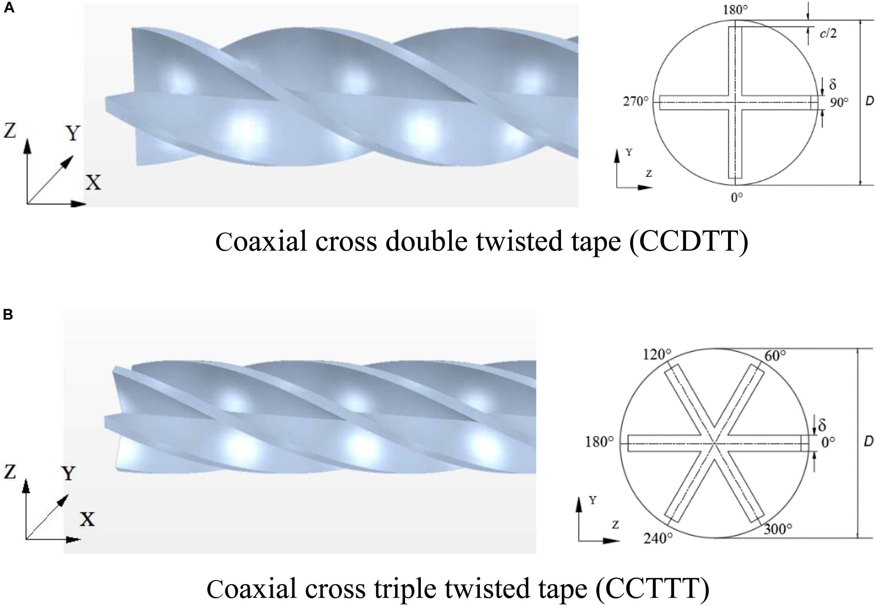
Figure 1. The geometry and cross-section view of the tubes with CCTT. (A) Coaxial cross double twisted tape (CCDTT). (B) Coaxial cross triple twisted tape (CCTTT).
The diameter (D) of the tube is 0.012 m, and the length (L) is 0.3 m. CCTTs with the thickness (δ) of 0.001 m are fitted in the tube. The twist ratio (y = H/D), defined as a ratio of the 180-degree twist pitch to the tube diameter, are 2, 3, 4, and infinity. The clearance ratio (CR = c/D), defined as a ratio of the clearance between the edge of the tape and the tube wall to the tube diameter, is set 0 to eliminate its effect on heat transfer. The working fluids are water (Pr = 7–8), 68# lubricating oil (Pr = 870–900), and FLiBe molten salt (Pr = 14–15). Their thermo-physical properties are assumed to be temperature-dependent.
Reynolds number (Re), Nusselt number (Nu), and friction factor (f) are defined as follows:
where ρ is density, u is inlet mean velocity, D is inner tube diameter, μ is fluid dynamic viscosity, λ is fluid thermal conductivity, h is heat transfer coefficient, L is tube length, and ΔP is pressure drop.
According to our results of the simulation, coaxial cross twisted tapes have a strong mixing effect due to induced swirl flow. The heat transfer coefficient at the wall quickly dropped and became stable at l = 0.03 m. In this case, a 10-times longer tube length is enough to give fully developed laminar flow, and the Nusselt number is calculated from the average heat transfer coefficient of the wall at the fully developed region (l = 0.24 m).
Numerical Simulation and Model
Simplifying Assumptions
The mathematical model involves the prediction of flow and heat transfer behaviors. Some simplified assumptions are required to apply the conventional flow equations and energy equations to model the heat transfer process in the tube with twisted tape. These major assumptions are: (1) the flow through the tube with twisted tape is laminar and incompressible, (2) the flow is in a steady state, (3) natural convection and thermal radiation are neglected, and (4) the thermo-physical properties of the fluid are temperature dependent. For FLiBe, its physical properties are defined by the correlations in the corresponding temperature range (650–700°C) from the liquid salt database (Sohal et al., 2010).
Governing Equations
The problem under consideration is assumed to be three-dimensional, laminar, and steady. Heat conduction in the twisted tape is neglected. Equations of continuity, momentum, and energy for the fluid flow are given below in the tensor form,
Continuity equation:
Momentum equations:
Energy equation:
Boundary Conditions
At the inlet, the fully developed profile of velocity is specified in Eq. 7 and the exit is set to pressure outlet.
where um is the mean velocity. R is the tube inner radius, and r is the radial position.
The Reynolds number used in the computation is referred to in the inlet values, which is set from 100 to 1,100. The exit condition is set as a pressure outlet, where the pressure is the same as the reference pressure (p = 101.325 kPa). The constant wall temperature boundary condition is adopted in all simulation calculations. Considering the evident difference among working fluids’ industrial applications, the temperature of inlet fluid and inner wall for water, lubricating oil, and FLiBe are set constant at 10, 40, 650°C and 40, 60, 700°C, respectively. The adiabatic thermal boundary condition is adopted on the surface of twisted tape, since its thermal effects can be ignored. On the tube walls and surface of twisted tapes, no-slip conditions are imposed.
Numerical Method
In this work, the CFD software STAR-CCM+ 10.02 (CD-adapco, 2015) is used for numerical computations and data post-processing. It provides a finite volume method fluid dynamics solution using the common Semi-Implicit Method for Pressure-Linked Equations (SIMPLE) with Rhie-Chow interpolation for pressure-velocity coupling and algebraic multi-grid preconditioning. For mesh generation, STAR-CCM+ provides tetrahedral, polyhedral, and trimmed (hexahedral) meshes. Prism layers of mesh cells can be included for modeling heat transfer and turbulence at important surfaces. For steady incompressible flow simulation, the second-order upwind discretization schemes for momentum and energy equations are employed in the numerical model of this study. Pressure-velocity coupling is handled by the Segregated Flow Model, which is a modified SIMPLE-type algorithm using a collocated grid arrangement.
Grid Independent Test
The grid independent test has been performed for the physical model to which the polyhedral grid type is applied. To improve the accuracy of the near-wall flow solution, prism layer mesh is applied to the near-wall grid and in the vicinity of the twisted tape. Four grid systems with approximately 1,258,000, 1,658,000, 2,172,500, and 3,170,770 cells are applied to calculate a baseline case of Nusselt number (Nu) and friction factor (f) in which Re = 1000, y = 3.0. Results show that the difference in Nusselt numbers and friction factors between 2,172,500 and 3,170,770 cells are 0.77 and 0.3%, respectively. Considering both convergent time and solution precision, the grids with 2172500 cells are used for the computational model.
Validation of the Numerical Model
To validate the accuracy of the numerical model, the simulation results of the Nusselt number and friction factor of the tube inserted with TT are compared with experimental results (Wongcharee and Eiamsa-Ard, 2011). In Table 1, simulations are done in a 1,000 mm long, 19 mm diameter tube fitted with 1 mm thickness, 18 mm width typical twisted tape with different twist ratio (y = 3,4,5), which are the same with each experiment. The overall deviations of the calculated f and Nu from the experimental results are found to be within ± 8% and ± 13%, respectively.
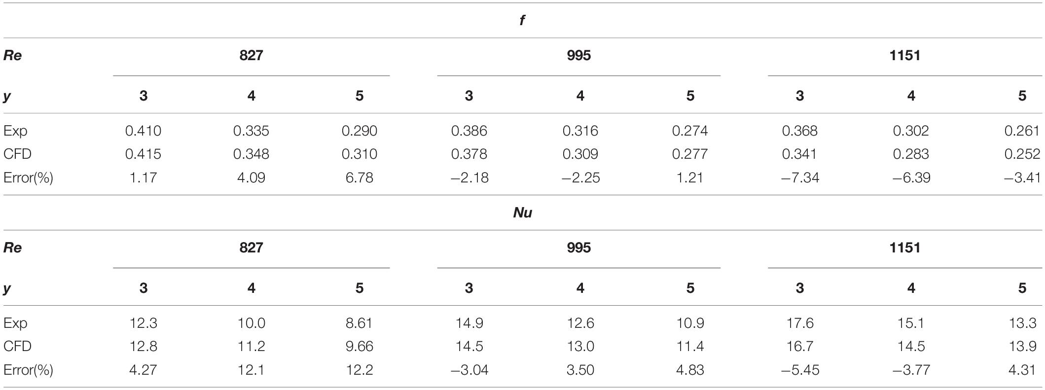
Table 1. Comparison of the CFD results with experimental results (Wongcharee and Eiamsa-Ard, 2011).
The numerical model is also tested by comparing results with the semi-empirical correlation (9), (10) which was developed by Manglik and Bergles (1993a) under fully developed flow conditions. The verifications are conducted for conditions Re = 110–1,000, y = 3. The other dimensions are the same with our physical model. Table 2 shows that the deviations of the present simulations from correlations were mostly within ± 4.8% and ± 7.3%, respectively. The maximum deviation of f and Nu are 14.2 and 7.5%, respectively. The comparison shows that the numerical model is benchmarked against the previous experiment and empirical correlation. Concerning that CCTT and TT produce similar swirl flow and have the same mechanism of heat transfer enhancement, the numerical model for TT can be also applied to CCTT.
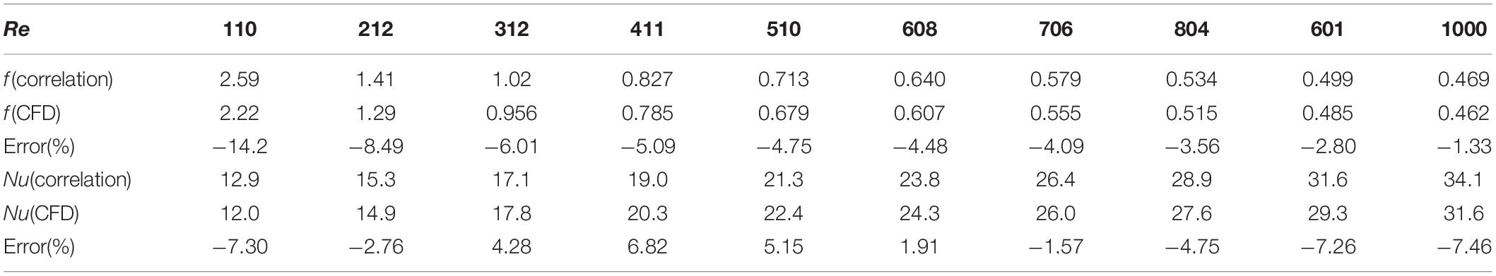
Table 2. Comparison of the CFD results with empirical correlation (Manglik and Bergles, 1993a).
Results and Discussion
Characteristics of Heat Transfer for FLiBe
In this section, simulation results of the velocity profile, friction factor, temperature profile, Nusselt number, and overall heat transfer performance of the plain tube fitted with TT and CCTTs are shown and analyzed. Previous research (Liu et al., 2017a, 2018) on CCTTs have investigated the twist ratio effect on its performance, and hence we chose the results of twist ratio y = 3 as a representative case in the following analysis.
Friction Factor and Effect on Velocity Profiles
With multiple twisted tapes in the tube, CCTTs shall have prominent disturbance on the velocity field. The contour plot of the streamline of FLiBe through the tube fitted with a CCTTT (y = 3) at l = 0.24 m, Re = 720 is displayed in Figure 2. It can be seen that six longitudinal vortices are generated around the CCTTT as it twists. These longitudinal vortices would induce considerable centrifugal force which results in the mixing of core flow and boundary flow, and hence effectively disturb the velocity profile and the temperature distribution of the core flow. This result also implies that CCTT has good disturbance on FLiBe even though it has high viscosity.
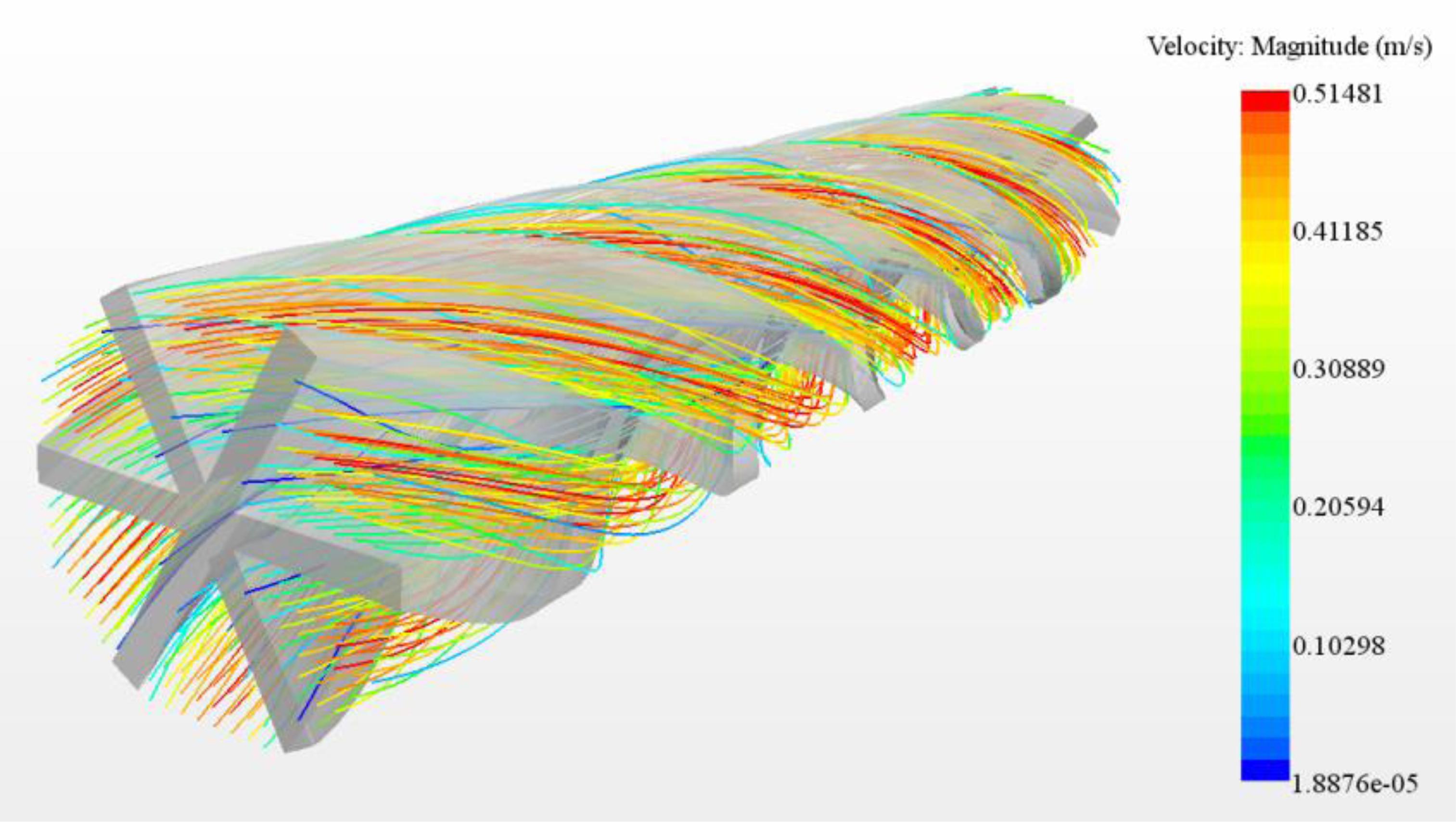
Figure 2. The streamline of the tube fitted with CCTTT (y = 3) at l = 0.24 m, Re = 720.
To make a comparison between disturbance of CCTT and TT on the velocity field, the velocity profiles of FLiBe in the plain tube and the tube fitted with TT, CCDTT, and CCTTT (y = 3, l = 0.24 m, Re = 720) are shown in Figure 3. Compared to the plain tube, the TT and CCTTs can all significantly change the velocity distribution of FLiBe. The major difference is that the core flow is accelerated and split into symmetric parts, which is the result of twisted tape’s partitioning and the centrifugal force of swirl flow. This can be determined more easily from the streamline in Figure 2.
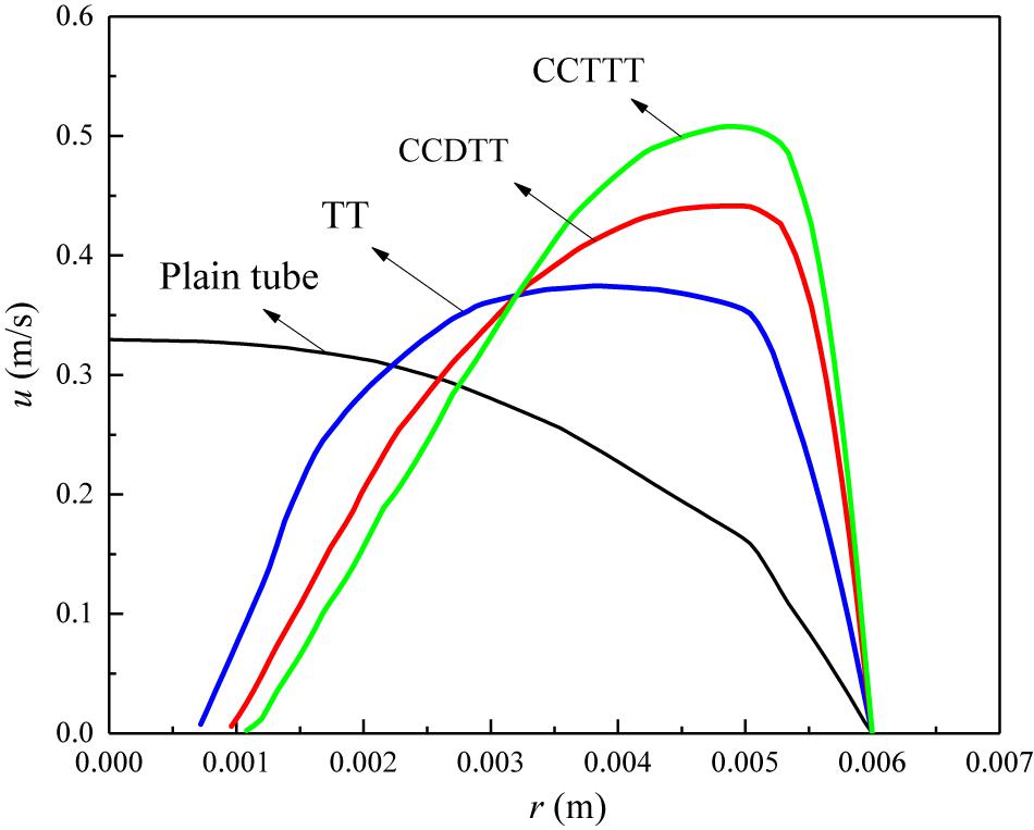
Figure 3. The velocity profile of FLiBe in the plain tube and the tube fitted with TT, CCDTT, and CCTTT (y = 3) at l = 0.24 m, Re = 720.
Compared to TT, the CCDTT has a stronger blockage effect and can divide the flow into four swirls, and therefore the velocity profile of FLiBe with CCDTT has a higher value of velocity and the core flow is closer to the wall. Hence, it induces a higher velocity gradient near the tube wall, which can be determined from the steep slope. Such great disturbance on the velocity profile is particularly effective for high viscosity fluid like FLiBe which usually has a low inlet velocity. All the above mechanisms show that CCTTT has a stronger effect than CCDTT due to greater partitioning and blockage.
One of the biggest side effects of utilizing the passive device for heat transfer enhancement is the increased pressure drop. Figure 4 shows the friction factor as a function of the Reynolds number in the flow of FLiBe in the plain tube and the tube fitted with TT, CCDTT, and CCTTT, y = 3. Apparently, the friction factor in the tube fitted with CCTT is larger than those of the tube with TT and the plain tube under the same conditions. In the present studied range with twist ratio y = 3, the friction factor of FLiBe in the tube with CCDTT and CCTTT are, respectively, 9.5–12.2 and 19.8–23.4 times of that in the plain tube and 2.22–2.32 and 4.26–4.83 times of that in the tube with TT.
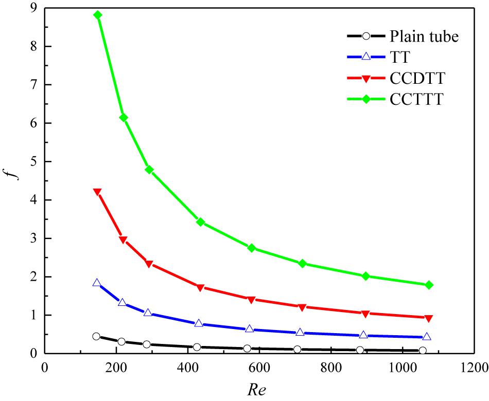
Figure 4. Variation of friction factor with the Reynolds number for FLiBe in the plain tube and the tube fitted with TT, CCDTT, and CCTTT (y = 3).
The additional pressure drop of FLiBe flow with CCTT can be explained by following reasons: (1) the CCTTs provide greater partitioning and blockage on the tube cross-section, which accelerates flow velocity and reduces the hydraulic diameter; (2) the CCTTs remarkably increase the surface area of the tape; and (3) the swirl flow notably increases the near-wall velocity gradient, which results in higher pressure drop.
Heat Transfer Coefficient and Effect on Temperature Profiles
The high friction is actually the price of enhancing the heat transfer of fluid. Figure 5 shows the variation of the Nusselt number with the Reynolds number for FLiBe in the plain tube and the tube fitted with TT, CCDTT, and CCTTT, y = 3. As expected, the tube fitted with CCTTs have better enhancement on the Nusselt number than those of the tube with TT and the plain tube under the same conditions. In the present studied range with twist ratio y = 3, the Nusselt number of FLiBe in the tube with CCDTT and CCTTT are, respectively, 2.32–3.6 and 2.99–3.97 times of that in the plain tube and 1.38–1.39 and 1.53–1.79 times of that in the tube with TT.
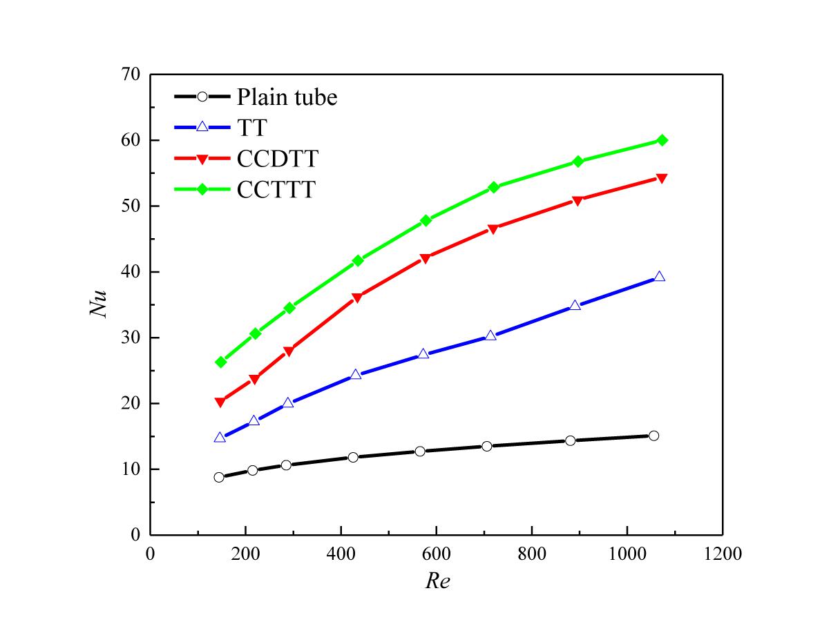
Figure 5. Variation of the Nusselt number with the Reynolds number for FLiBe in the plain tube and the tube fitted with TT, CCDTT, and CCTTT (y = 3).
In general, the disturbance on velocity profile can enable the CCTTs to mix the core flow with boundary flow, and therefore effectively affects the temperature distribution of FLiBe. To prove this expectation, the dimensionless temperature profiles of FLiBe in the plain tube and the tube fitted with TT, CCDTT, and CCTTT (y = 3, l = 0.24 m, Re = 720) are compared in Figure 6 in which the dimensionless temperature is defined as Tθ = (Tw−T)/(Tw−Tm).
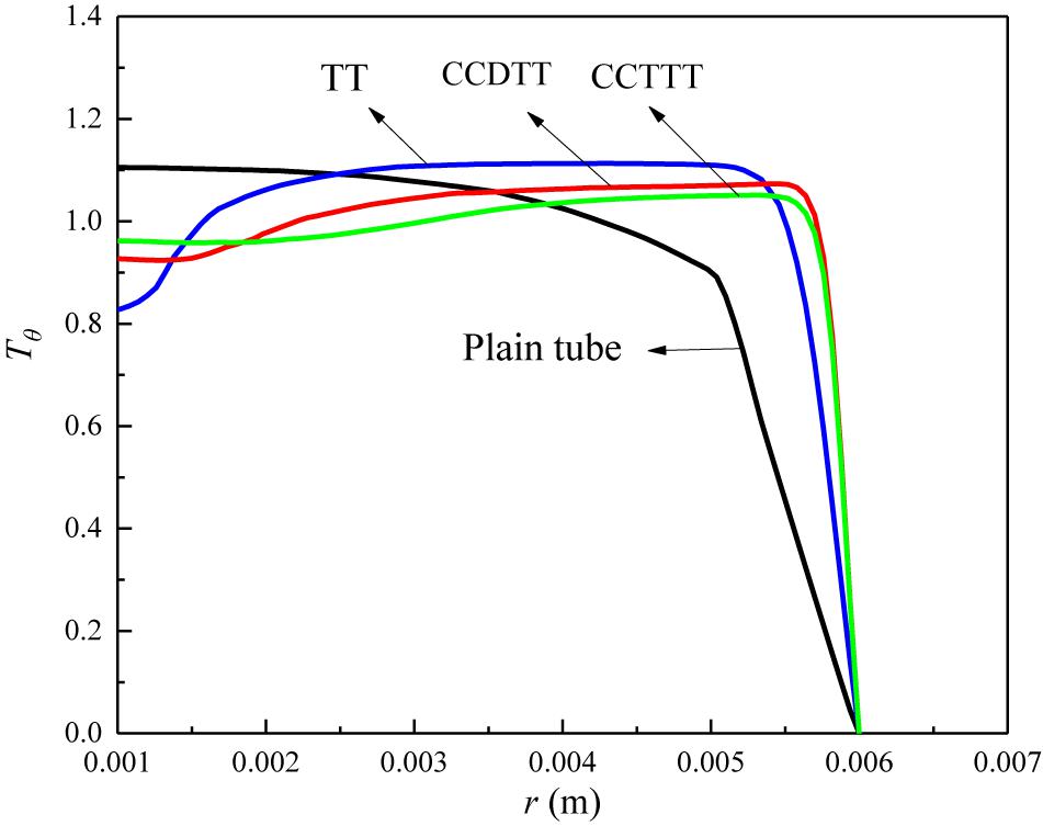
Figure 6. The temperature profile of FLiBe in the plain tube and the tube fitted with TT, CCDTT, and CCTTT (y = 3) at l = 0.24 m, Re = 720.
Figure 6 indicates that the twisted tape can significantly augment the near-wall temperature gradient of FLiBe and uniform the temperature distribution of core flow. This is because the blockage of twisted tape and centrifugal force induced by swirl flow can both accelerate the velocity of flow and therefore improve the near-wall temperature gradient and convective heat transfer. Moreover, the swirl flow also enables the core flow mix with boundary flow, which notably uniforms the temperature profile of core flow. As seen from the slope of the near-wall temperature, the CCTTs can produce a greater temperature gradient and a thinner thermal boundary layer than TT. In summary, the swirl flow’s disturbance on the velocity field changes the temperature field and enhances the heat transfer.
It is also notable in Figure 5 that the CCTTT has better augmentation on heat transfer than CCDTT while the trends of the Nusselt number with the variation of the Reynolds number are similar for both tapes. This phenomenon indicates that CCDTT and CCTTT share the same mechanism of heat transfer enhancement whose effect would arise as more longitudinal vortices are generated (Guo et al., 2005).
Based on the above analysis of temperature profiles, the enhancement on heat transfer can be explained by three reasons: (1) the highly increased flow velocity enhances the convective of heat transfer; (2) more longitudinal vortices would induce considerable centrifugal force to mix core flow with boundary flow, and hence effectively uniform the temperature of core flow and make the thermal boundary layer thinner; and (3) the swirl flow increases the flow path.
Overall Heat Transfer Performance
As analyzed in previous sections, the enhancement of heat transfer and flow resistance all increase with the twisted tape inserts. To evaluate the comprehensive effect of heat transfer augmentation under given pumping power, a performance evaluation criteria (PEC) (Fan et al., 2009) is employed and defined as follow:
where Nu0 and f0 are the Nusselt number and the friction factor of the plain tube, respectively. For power −1/6 in the equation, we apply the Darcy–Weisbach equation and Sieder-Tate equation for the friction factor and Nusselt number of laminar flow in a circular tube. Defining PEC under the constraint of pumping power satisfies the industrial need since how much heat transfer can be enhanced with the same pumping power provides better quantitative parameters than those concerned at the identical pressure drop. The variation of PEC with the Reynolds number for FLiBe in the tube fitted with TT, CCDTT, and CCTTT, y = 3 are displayed in Figure 7.
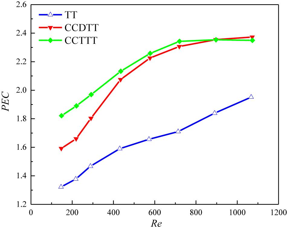
Figure 7. Variation of PEC with the Reynolds number for FLiBe in the tube fitted with TT, CCDTT, and CCTTT (y = 3).
In general, the PEC value tends to rise with an increasing Reynolds number for all twisted tapes among which the CCTTs have much better heat transfer performance than TT. In the present studied range with twist ratio y = 3, the PEC of FLiBe in the tube with CCDTT and CCTTT are, respectively, 1.2–1.22 and 1.2–1.38 times of those in the tube with TT. Notably, the heat transfer performance of the tube fitted with CCTTT would decrease in a high Reynolds number near the transition regime. This is because with the increase of the Reynolds number, the increase of the friction factor of the tube with CCTTT is stronger than the enhancement of the Nusselt number. In the range of numerical simulation, the highest PEC 2.73 is obtained by CCTTT (y = 2) at a Reynolds number of 582.
Comparison of Different Fluids
As mentioned in section “Introduction,” though the CCTTs have prominent enhancement on laminar convective heat transfer of lubricating oil (Liu et al., 2017a, b, 2018), its variation of performance with different fluids is still unknown. To investigate whether the CCTTs are advantageous on heat transfer enhancement of high viscosity molten salt, the results of water and lubricating oil are presented and compared with FLiBe.
Comparison of Velocity and Temperature Profiles
Various fluids’ distinction on viscosity may induce a different level of the CCTTs’ disturbance on the velocity and temperature profile, though most research (Kunlabud et al., 2017; Liu et al., 2017a, b, 2018; Saysroy and Eiamsa-Ard, 2017; Bahiraei et al., 2019; Khanmohammadi and Mazaheri, 2019) focused on one specific fluid. To investigate the effect, the velocity, and temperature profiles of FLiBe, water, and lubricating oil in the tube fitted with CCDTT are compared in Figures 8, 9, respectively. The velocity profiles are normalized by each average velocity (um) to eliminate the differences among inlet velocity values. Figure 8 indicates no obvious difference between the velocity profiles of various fluids, which demonstrates that the CCTTs can effectively disturb the velocity profile with the same level for various working fluids at the laminar regime. This phenomenon testifies that the CCTTs are effective in affecting the velocity distribution even with high viscosity molten salt.
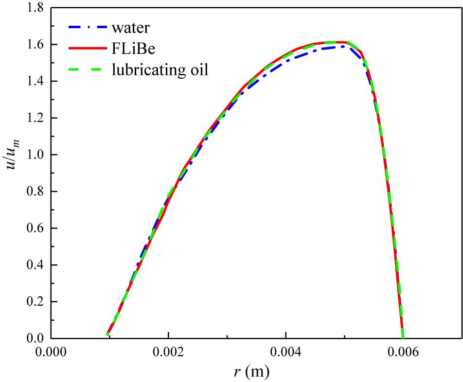
Figure 8. The velocity profile of different fluids in the tube fitted with CCDTT (y = 3) at l = 0.24 m, Re = 720.
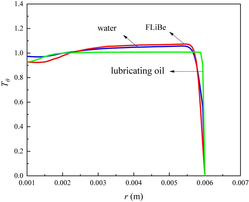
Figure 9. Temperature profile of different fluids in the tube fitted with CCDTT (y = 3) at l = 0.24 m, Re = 720.
For the temperature profile, however, Figure 9 indicates different level of CCTTs disturbance on various working fluids. The thermal boundary layer of lubricating oil is thinner than water and FLiBe. It can be attributed to the much higher Prandtl number of lubricating oil. A higher Prandtl number means a higher ratio of momentum diffusivity to the thermal diffusivity, and generally indicates a higher ratio of velocity boundary layer thickness to thermal boundary layer thickness.
The comparison between Figures 8, 9 shows that lubricating oil has a thinner thermal boundary layer than the other working fluids while the velocity boundary layer shows no difference. Since the fluids with higher viscosity would have thinner thermal boundary layers relative to the velocity boundary layer and CCTTs can induce the same level of disturbance on the velocity field, the thermal boundary layer of fluids with higher Prandtl numbers would be reduced much more, and hence the heat transfer enhancement is better. Figure 10 indicates the local heat transfer coefficient ratio of various working fluids in a tube fitted with CCDTT (y = 3, l = 0.24 m, Re = 720). It shows that lubricating oil and FLiBe have a higher ratio of heat transfer coefficient than water. In general, a thinner thermal boundary layer means a higher temperature gradient and heat transfer coefficient and Figure 10 testifies that CCDTT has better enhancement on higher Prandtl number fluids.
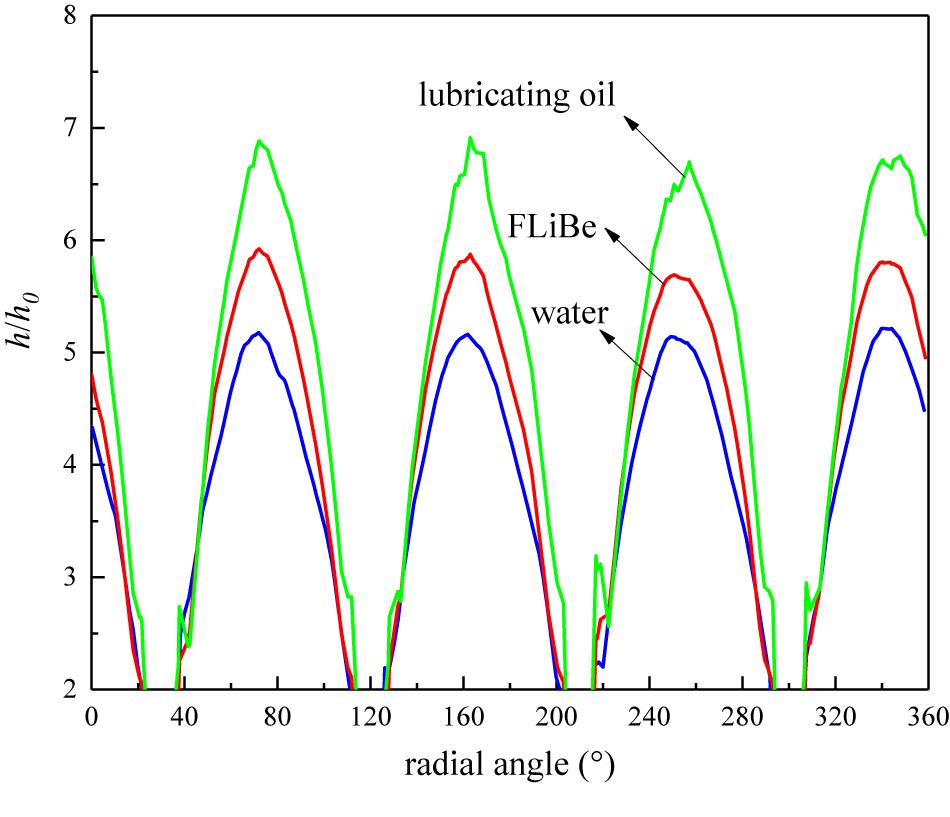
Figure 10. Local heat transfer coefficient ratio of various working fluids in the tube fitted with CCDTT (y = 3) at l = 0.24 m, Re = 720.
In summary, CCTTs have better enhancement on the heat transfer of higher Prandtl number fluids, whose momentum diffusivity dominates the heat transfer behavior. It also indicates that the CCTTs have potential on the improvement of heat transfer of other high viscosity molten salts.
Friction Factor and Nusselt Number Comparison
All the previous comparisons of results focus on the qualitative research at representative Reynolds numbers. To give a quantitative investigation of different fluids in the laminar flow regime, comparisons of friction factor ratio (f/f0) and Nusselt number ratio (Nu/Nu0) in the tube fitted with CCDTT and CCTTT (y = 3) are presented in Figures 11, 12, respectively. As Figure 11 shows, the CCTTs have almost the same degree of increase in pressure drop for different fluids, which can be explained by the same level of velocity disturbance of different fluids in Figure 8. The similar velocity profile indicates a similar velocity gradient, and hence the increase of pressure drop, compared with the plain tube, should be approximate.
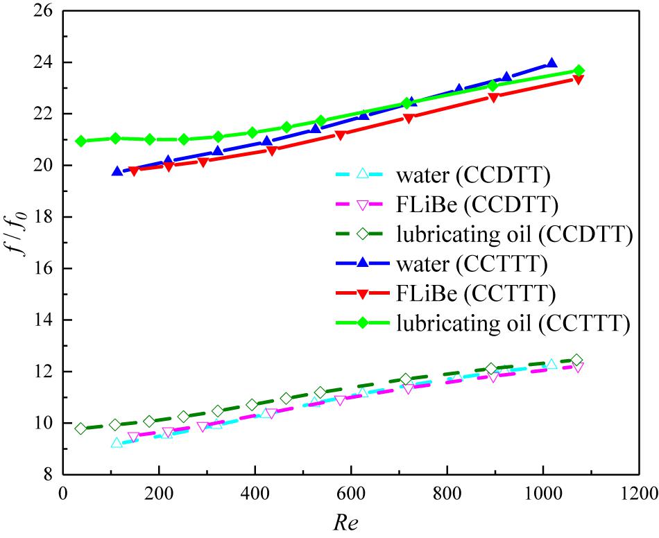
Figure 11. Variation of friction factor ratio with the Reynolds number for various fluids in the tube fitted with CCDTT and CCTTT (y = 3).
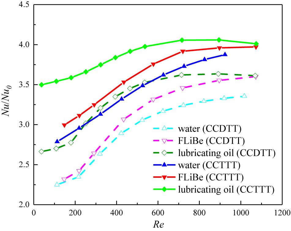
Figure 12. Variation of Nusselt number ratio with the Reynolds number for different fluids in the tube fitted with CCDTT and CCTTT (y = 3).
On the other hand, the increases in the heat transfer of different fluids show a prominent difference. Figure 12 show that the CCTTs have better enhancement on the heat transfer with higher Prandtl number fluids in the present range of the Reynolds number, which corresponds with previous analysis of the temperature profile. For exact comparison, the Nusselt number ratio of oil in the tube with CCDTT and CCTTT are, respectively, 1.047 and 1.035 times of that in FLiBe and 1.117 and 1.088 times of that in the water at Re = 720. Higher Prandtl number fluids can have greater disturbance on a temperature profile from CCTTs since momentum diffusivity dominates the heat transfer behavior of viscous fluids.
Overall Heat Transfer Performance Comparison
Coupling the results of the friction factor and heat transfer, the variation of PEC with the Reynolds number for different fluids in the tubes fitted with TT, CCDTT, and CCTTT (y = 3) are displayed in Figure 13. From the analysis of the friction factor ratio and Nusselt number ratio among different fluids, it is easy to find that Figure 13 has a similar trend to Figure 12. This is because the CCTTs can induce the same degree of disturbance on the velocity field (i.e., pressure drop increase) but a higher level of heat transfer augmentation in high viscosity fluids. It also implies that the differences in the thermophysical property have a stronger effect on the enhancement of heat transfer than pressure drop in the tube fitted with CCTTs. The higher the Prandtl number is, the better the heat transfer enhancement of CCTTs becomes. In other words, the CCTTs can have better overall heat transfer performance with a higher Prandtl number fluid. At Re = 720, the PEC of oil in the tube with CCDTT and CCTTT are, respectively, 1.042 and 1.031 times of those in FLiBe and 1.113 and 1.088 times of those in water.
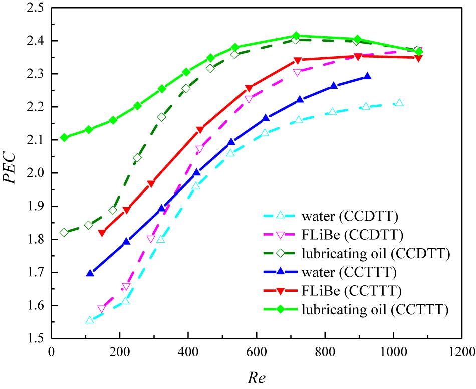
Figure 13. Variation of PEC with the Reynolds number for different fluids in the tube fitted with CCDTT and CCTTT (y = 3).
Correlations of Nusselt Number and Friction Factor
Analysis of the Correlations of Typical Twisted Tapes
Until now, many correlations have been developed for typical and modified twisted tapes (Garg et al., 2016). For TT, Manglik and Bergles developed their semi-empirical correlations of friction factor and Nusselt number (Sw = 300–1400) (Manglik and Bergles, 1993a), as shown in Eqs 9 and 10:
where Sw is a dimensionless swirl parameter that accounts for centrifugal force effect (Eq. 13); Gz is Graetz number (Gz = MCp/λL); Pr is Prandtl number; Reax is Reynolds number at axial velocity; Ra is Rayleigh number that describes the buoyancy effect; φ and ψ are the cross section (Eq. 11) and hydraulic diameter parameters (Eq. 12); and μf and μw are the fluid dynamic viscosity at fluid and wall temperature.
These correlations were developed to comprehensively describe the TT’s main effects on flow, including blockage, and swirl flow. One outstanding point is that these two effects were, respectively, correlated by the analytical solution and the experimental results since the blockage effect is numerically solvable, whereas swirl flow is mostly described by the empirical method.
Blockage Effect
For the blockage effect, Manglik and Bergles applied the analytical solution of fully developed laminar flow in a semi-circular duct (y = ∞, δ = 0) to solve the constant coefficient 15.767 as a numerical baseline solution of the friction factor. Concerning that the thickness of tape inserts will also decrease the cross-sectional area of the tube, and hence increase velocity and friction, two parameters that describe the tape thickness’s effects on cross-sectional areas and hydraulic diameters were introduced. The first one is the cross-section parameter φ, as shown in Eq. 11:
The second one is the hydraulic diameter parameter, as shown in Eq. 12:
To describe the effect of blockage on heat transfer, the constant coefficient 4.612 and a function of Graetz number (Gz, a dimensionless number that determines the length for thermally fully developed flow) were numerically solved under the analytical solution of a semi-circular duct model, which gave a good baseline solution of fully developed laminar flow’s (y = ∞) Nusselt number. Having these coefficients and parameters derived from theoretical analysis can provide a simple and precise description of the blockage effect on fluids.
Swirl Flow Effect
Besides the blockage effect, the twisted tapes also induce strong swirl flow, as shown in Figure 2. For the effect of swirl flow, the empirical correlating method was used to reveal the sophisticated helically rotating fluid flow. The swirl parameter that represents the balance of centrifugal, convective inertia, and viscous forces was defined to describe the intensity of swirl flow:
where us is the actual swirl velocity in the tube and defined as:
Therefore, the characteristics of swirl flow were described by Sw, instead of Re, in the correlations of friction factor and Nusselt number. In the end, the blockage and swirl flow effect can be combined and correlated by the asymptotic matching method which yields Eqs 9 and 10.
New Unified Correlations for Twisted Tapes and Coaxial Cross Twisted Tapes
Since CCTTs and TT have the alike geometry and the same mechanism of heat transfer improvement, it is reasonable to develop their correlations based on TT’s correlations Eqs 9 and 10, proposed by Manglik and Bergles. For the blockage effect, parameters that describe the changes of the cross-sectional area and hydraulic diameter can be modified according to the geometry of CCTTs. The cross-section and hydraulic diameter parameters of CCDTT are defined in Eqs 15 and 16, respectively:
The cross-section and hydraulic diameter parameters of CCTTT are defined in Eqs 17 and 18, respectively:
For the concern of practical use, the cross section and hydraulic diameter parameters of TT, CCDTT, and CCTTT can be re-defined in a unified form where the second order term δ2/D2 is omitted. The cross-section parameter is re-defined as:
The hydraulic diameter parameter is re-defined as:
where n is the tape number and coefficient m shall be set 2, 8, or for TT, CCDTT, or CCTTT, respectively.
For the swirl flow effect, the swirl parameter that describes the intensity of tape-twist induced swirl flow is defined as the same as Eq. 13 except that the cross-section parameter φ shall use the unified form in Eq. 19. In the heat transfer correlation, the numerical results show that the swirl flow effect surpasses the free convective effect, where Gr< < Sw2. This is because the flow in research has a low Grashof number, and therefore the effect of buoyancy force can be neglected in the correlation of heat transfer. Finally, the Nusselt number is developed as the function of Sw, Gz, and Pr. Based on the results of numerical simulations with FLiBe, water, and lubricating oil, the correlations of the Nusselt number and friction factor in the tube fitted with TT, CCDTT or CCTTT are uniformly developed and defined as follow:
where A and B are various constant coefficients for TT and CCTTs. As for TT, A = 59.24, B = 3.81; for CCDTT and CCTTT, A = 47.38, B = 5.67.
For Eqs 21 and 22, the range of Reynolds number, Prandtl number, and twist ratio are 100–1,100, 7–900, and 2–4, respectively. The comparison of numerical results with predicted values of the Nusselt number and friction factor are shown in Figure 14. The predicted values are in good agreement with the numerical simulations and deviations of Nu and f are within ± 20% and ± 12%, respectively.
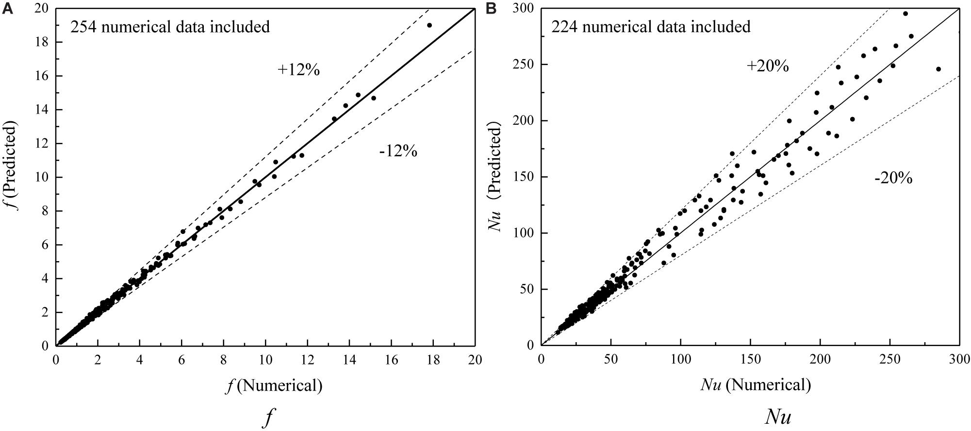
Figure 14. Comparison of numerical results with predicted values of Nusselt number and friction factor. (A) f. (B) Nu.
Conclusion
The characteristics of heat transfer and friction factor of laminar flow for various working fluids in a circular tube with coaxial cross twisted tape (CCTT) have been investigated numerically. The streamline, velocity profiles, temperature profiles, and performance evaluation criteria are all presented for analysis and the conclusion are summarized as follows:
(1) The velocity and temperature profiles of the tube fitted with different twisted tape reveal that the CCTTs can produce stronger swirl flow and improve the near-wall gradient of velocity and temperature. For FLiBe, the CCTTs are more effective in reducing the thermal boundary layer of FLiBe because of its thicker velocity boundary layer. For different fluids, the CCTTs’ disturbance on velocity profiles is similar while the reduction on the thermal boundary layer would intensify with the increase of the Prandtl number.
(2) The numerical results show that the CCTTs can greatly enhance the heat transfer, though the pressure drop also increases. The plots of PEC (y = 3) for FLiBe indicates that the overall performance of CCDTT and CCTTT are respectively 1.2-1.22 and 1.2-1.38 times of that in the tube with TT. The maximum PEC value 2.73 is obtained by CCTTT (y = 2) at Re = 582. For different fluids, the CCTTs provide better overall performance with higher Prandtl number fluids.
(3) The semi-empirical correlations of the Nusselt number and friction factor of various fluids for TT, CCDTT, and CCTTT are uniformly developed based on numerical results. The maximum discrepancy between the correlative results and numerical results for the Nusselt number and friction factor are found to be ± 20% and ± 12%, respectively.
Future Work
The CCTTs heat transfer enhancement performance with FLiBe have been numerically studied and testified as a feasible method on high Prandtl number fluids, though further research could be done on experimental demonstration and geometry modification simulation. There are various types of geometry modifications that can be applied on the CCTTs, including alternative clockwise and counter-clockwise (Eiamsa-Ard and Promvonge, 2010), notched tape (Rahimi et al., 2009), multiple tapes (Piriyarungrod et al., 2018), and grooved tubes (Lu et al., 2015). These modifications could either periodically mix swirl flow in each channel or introduce perturbation near the wall so that heat transfer resistance is further reduced. Through experimental demonstration, the semi-empirical correlation in this work could be testified and corrected based on measurement.
Data Availability Statement
The raw data supporting the conclusions of this article will be made available by the authors, without undue reservation, to any qualified researcher.
Author Contributions
This work was done during the undergraduate thesis of ZY under the instruction of XC and MD. The basic of new coaxial cross twisted tape performance has been previously researched by XL and she provided lots of help and insights to this work. ZG also helped ZY a lot on this work. All authors contributed to the article and approved the submitted version.
Conflict of Interest
The authors declare that the research was conducted in the absence of any commercial or financial relationships that could be construed as a potential conflict of interest.
References
Abed, A. M., Hasan, S. M., Hussein, Z., Fadhil, D., and Abdulkadhim, A. (2018). Numerical analysis of flow and heat transfer enhancement in a horizontal pipe with P-TT and V-Cut twisted tape. Case Stud. Ther. Engin. 12, 749–758. doi: 10.1016/j.csite.2018.10.004
Agarwal, S., and Rao, M. R. (1996). Heat transfer augmentation for the flow of a viscous liquid in circular tubes using twisted tape inserts. Int. J. Heat Mass Trans. 39, 3547–3557. doi: 10.1016/0017-9310(96)00039-7
Amini, A., Miller, J., and Jouhara, H. (2017). An investigation into the use of the heat pipe technology in thermal energy storage heat exchangers. Energy 136, 163–172. doi: 10.1016/j.energy.2016.02.089
Bahiraei, M., Nima, M., Mehran, S. M., and Moayedi, H. (2019). Thermal performance of a new nanofluid containing biologically functionalized graphene nanoplatelets inside tubes equipped with rotating coaxial double-twisted tapes. Int. Commun. Heat. Mass Trans. 108:104305. doi: 10.1016/j.icheatmasstransfer.2019.104305
Chang, C., Adriano, S., Zhiyong, W., Xin, L., Yongliang, L., Mingzhi, Z., et al. (2018). Enhanced heat transfer in a parabolic trough solar receiver by inserting rods and using molten salt as heat transfer fluid. Appl. Energy 220, 337–350. doi: 10.1016/j.apenergy.2018.03.091
Chen, Y.-S., Jian, T., Shen-De, S., Qiang, S., Yuan, F., Zhong-Feng, T., et al. (2017). Characteristics of the laminar convective heat transfer of molten salt in concentric tube. Appl. Ther. Engin. 125, 995–1001. doi: 10.1016/j.applthermaleng.2017.07.043
Chen, Y. S., Tian, J., Fu, Y., Tang, Z. F., Zhu, H. H., and Wang, N. X. (2018). Experimental study of heat transfer enhancement for molten salt with transversely grooved tube heat exchanger in laminar-transition-turbulent regimes. Appl. Therm. Engin. 132, 95–101. doi: 10.1016/j.applthermaleng.2017.12.054
Chiba, S., Shinya, C., Saburo, T., Kazuhisa, Y., and Akio, S. (2001). Heat transfer enhancement for a molten salt Flibe channel. Fusion Technol. 39 2P2, 779–783. doi: 10.13182/FST01-A11963333
Chiba, S.-Y., Kazuhisa, Y., Hidetoshi, H., Saburo, T., and Akio, S. (2006). Numerical research on heat transfer enhancement for high Prandtl-number fluid. Fusion Engin. Design. 81, 513–517. doi: 10.1016/j.fusengdes.2005.08.046
Dave, A., Sun, K., and Hu, L. (2018). Numerical simulations of molten salt pebble-bed lattices. Ann. Nuclear Energy 112, 400–410. doi: 10.1016/j.anucene.2017.10.037
Du, B.-C., Ya-Ling, H., Kun, W., and Han-Hui, Z. (2017). Convective heat transfer of molten salt in the shell-and-tube heat exchanger with segmental baffles. Int. J. Heat Mass Trans. 113, 456–465. doi: 10.1016/j.ijheatmasstransfer.2017.05.075
Eiamsa-Ard, S., and Promvonge, P. (2010). Performance assessment in a heat exchanger tube with alternate clockwise and counter-clockwise twisted-tape inserts. Int. J. Heat Mass Trans. 53, 1364–1372. doi: 10.1016/j.ijheatmasstransfer.2009.12.023
Fan, J., Ding, W. K., Zhang, J. F., He, Y. L., and Tao, W. Q. (2009). A performance evaluation plot of enhanced heat transfer techniques oriented for energy-saving. Int. J. Heat Mass Trans. 52, 33–44. doi: 10.1016/j.ijheatmasstransfer.2008.07.006
Garbrecht, O., Bieber, M., and Kneer, R. (2017). Increasing fossil power plant flexibility by integrating molten-salt thermal storage. Energy 118, 876–883. doi: 10.1016/j.energy.2016.10.108
Garg, M., Himanshu, N., Sourabh, K., and Shukla, M. K. (2016). Heat transfer augmentation using twisted tape inserts: A review. Renew. Sustain. Energy Rev. 63, 193–225. doi: 10.1016/j.rser.2016.04.051
Guo, Z.-Y., Tao, W.-Q., and Shah, R. (2005). The field synergy (coordination) principle and its applications in enhancing single phase convective heat transfer. Int. J. Heat Mass Trans. 48, 1797–1807. doi: 10.1016/j.ijheatmasstransfer.2004.11.007
He, Y., Li, L., Pengxiao, L., and Lianxiang, M. (2018). Experimental study on heat transfer enhancement characteristics of tube with cross hollow twisted tape inserts. Appl. Ther. Engin. 131, 743–749. doi: 10.1016/j.applthermaleng.2017.12.029
Hosseinnezhad, R., Rahim, H., Omid, A. A., Hamid, H. A., Mohit, B., Ali, K., et al. (2018). Numerical study of turbulent nanofluid heat transfer in a tubular heat exchanger with twin twisted-tape inserts. J. Therm. Analy. Calor. 132, 741–759. doi: 10.1007/s10973-017-6900-5
Jianfeng, L., Shen, X., Ding, J., Peng, Q., and Wen, Y. (2013). Convective heat transfer of high temperature molten salt in transversely grooved tube. Appl. Ther. Engin. 61, 157–162. doi: 10.1016/j.applthermaleng.2013.07.037
Kearney, D., Kellyb, B., Herrmannc, U., Cabled, R., Pachecoe, J., Mahoneye, R., et al. (2004). Engineering aspects of a molten salt heat transfer fluid in a trough solar field. Energy 29, 861–870. doi: 10.1016/S0360-5442(03)00191-9
Khanmohammadi, S., and Mazaheri, N. (2019). Second law analysis and multi-criteria optimization of turbulent heat transfer in a tube with inserted single and double twisted tape. Int. J. Ther. Sci. 145:105998. doi: 10.1016/j.ijthermalsci.2019.105998
Kunlabud, S., Varesa, C., Vichan, K., Pitak, P., and Smith, E. (2017). Heat transfer in turbulent tube flow inserted with loose-fit multi-channel twisted tapes as swirl generators. Theoret. Appl. Mechan. Lett. 7, 372–378. doi: 10.1016/j.taml.2017.11.011
Liu, X., Chun, L., and Bian, H. (2017a). “Enhanced Heat Transfer And Resistance Performance Of New Complex Twisted Tapes For Highly-Viscous Fluid Flow Inside Tubes,” in 17th international topical meeting on nuclear reactor thermal hydraulics, (Harbin: Harbin Engineering University).
Liu, X., Liu, Q., and Bo, H. (2017b). “Numerical Study on Heat Transfer and Resistance of a Tube Fitted With New Twisted Tapes for Lubricating Oil,” in in 2017 25th International Conference on Nuclear Engineering, (New York: American Society of Mechanical Engineers Digital Collection). doi: 10.1115/ICONE25-67766
Liu, X., Chun, L., Cao, X., and Yan, C. (2018). Numerical analysis on enhanced performance of new coaxial cross twisted tapes for laminar convective heat transfer. Int. J. Heat Mass Trans. 121, 1125–1136. doi: 10.1016/j.ijheatmasstransfer.2018.01.052
Lu, J., Jing, D., Tao, Y., and Xiangyang, S. (2015). Enhanced heat transfer performances of molten salt receiver with spirally grooved pipe. Appl. Ther. Engin. 88, 491–498. doi: 10.1016/j.applthermaleng.2014.09.020
Manglik, R., Agarwal, S. K., and Raja Rao, M. (1993). Heat transfer enhancement of intube flows in process heat exchangers by means of twisted-tape inserts. Troy, NY: Rensselaer Polytechnic Institute. Ph.D. thesis.
Manglik, R. M., and Bergles, A. E. (1993a). Heat transfer and pressure drop correlations for twisted-tape inserts in isothermal tubes: part I—laminar flows. J. Heat Trans. 115, 881–889. doi: 10.1115/1.2911383
Manglik, R. M., and Bergles, A. E. (1993b). Heat transfer and pressure drop correlations for twisted-tape inserts in isothermal tubes: Part II—Transition and turbulent flows. J. Heat Trans. 115, 890–896. doi: 10.1115/1.2911384
Meng, J.-A., Liang, X.-G., and Li, Z.-X. (2005). Field synergy optimization and enhanced heat transfer by multi-longitudinal vortexes flow in tube. Int. J. Heat Mass Trans. 48, 3331–3337. doi: 10.1016/j.ijheatmasstransfer.2005.02.035
Piriyarungrod, N., Manoj, K., Thianpongc, C., Pimsarnc, M., Chuwattanakulc, V., and Eiamsa-ard, S. (2018). Intensification of thermo-hydraulic performance in heat exchanger tube inserted with multiple twisted-tapes. Appl. Therm. Engin. 136, 516–530. doi: 10.1016/j.applthermaleng.2018.02.097
Promvonge, P. (2008). Thermal augmentation in circular tube with twisted tape and wire coil turbulators. Energy Convers. Manag. 49, 2949–2955. doi: 10.1016/j.enconman.2008.06.022
Rahimi, M., Shabanian, S. R., and Alsairafi, A. A. (2009). Experimental and CFD studies on heat transfer and friction factor characteristics of a tube equipped with modified twisted tape inserts. Chem. Engin. Proc. Process Inten. 48, 762–770. doi: 10.1016/j.cep.2008.09.007
Romatoski, R., and Hu, L. (2017). Fluoride salt coolant properties for nuclear reactor applications: A review. Anna. Nucl. Energy 109, 635–647. doi: 10.1016/j.anucene.2017.05.036
Ruengpayungsak, K., Saysroy, A., Wongcharee, K., and Eiamsa-Ard, S. (2019). Thermohydraulic performance evaluation of heat exchangers equipped with centrally perforated twisted tape: Laminar and turbulent flows. J. Ther. Sci. Technol. 14, JTST0002–JTST0002. doi: 10.1299/jtst.2019jtst0002
Sabharwall, P., Denis, C., Michael, G., Guiqiu, Z., Kumar, S., Mark, A., et al. (2014). Advanced heat exchanger development for molten salts. Nucl. Engin. Design. 280, 42–56. doi: 10.1016/j.nucengdes.2014.09.026
Saha, S., Gaitonde, U., and Date, A. (1989). Heat transfer and pressure drop characteristics of laminar flow in a circular tube fitted with regularly spaced twisted-tape elements. Exper. Therm. Fluid Sci. 2, 310–322. doi: 10.1016/0894-1777(89)90020-4
Saysroy, A., and Eiamsa-Ard, S. (2017). Enhancing convective heat transfer in laminar and turbulent flow regions using multi-channel twisted tape inserts. Int. J. Therm. Sci. 121, 55–74. doi: 10.1016/j.ijthermalsci.2017.07.002
Scarlat, R. O., and Peterson, P. F. (2014). The current status of fluoride salt cooled high temperature reactor (FHR) technology and its overlap with HIF target chamber concepts. Nucl. Instr. Meth. Phys. Res. Sec. A Accele. Spectr. Detec. Assoc. Equip. 733, 57–64. doi: 10.1016/j.nima.2013.05.094
Serrano-López, R., Fradera, J., and Cuesta-Lopez, S. (2013). Molten salts database for energy applications. Chem. Engin. Process. Proc. Intens. 73, 87–102. doi: 10.1016/j.cep.2013.07.008
Smithberg, E., and Landis, F. (1964). Friction and forced convection heat-transfer characteristics in tubes with twisted tape swirl generators. J. Heat Trans. 86, 39–48. doi: 10.1115/1.3687060
Sohal, M. S., Manohar, S., Ebner, M. A., Sabharwall, P., Sharpe, P., et al. (2010). Engineering database of liquid salt thermophysical and thermochemical properties. United States: Idaho National Laboratory (INL). doi: 10.2172/980801
Thorsen, R., and Landis, F. (1968). Friction and heat transfer characteristics in turbulent swirl flow subjected to large transverse temperature gradients. J. Heat Trans. 90, 87–97. doi: 10.1115/1.3597466
Toda, S., Shinya, C., Kazuhisa, Y., Masahiro, O., and Akio, S. (2002). Experimental research on molten salt thermofluid technology using a high-temperature molten salt loop applied for a fusion reactor Flibe blanket. Fus. Engin. Des. 63, 405–409. doi: 10.1016/S0920-3796(02)00195-3
Vignarooban, K., Xinhai, X., Arvayc, A., Hsua, K., and Kannan, A. M. (2015). Heat transfer fluids for concentrating solar power systems-a review. Appl. Energy 146, 383–396. doi: 10.1016/j.apenergy.2015.01.125
Watanabe, A., Shinji, E., Akio, S., and Hidetoshi, H. (2013). Evaluation of heat transfer characteristics of a sphere-packed pipe for Flibe blanket. Fus. Engin. Des. 88, 2357–2360. doi: 10.1016/j.fusengdes.2013.01.051
Wongcharee, K., and Eiamsa-Ard, S. (2011). Friction and heat transfer characteristics of laminar swirl flow through the round tubes inserted with alternate clockwise and counter-clockwise twisted-tapes. Int. Commun. Heat Mass Trans. 38, 348–352. doi: 10.1016/j.icheatmasstransfer.2010.12.007
Xiao, P., Guo, L., and Zhang, X. (2015). Investigations on heat transfer characteristic of molten salt flow in helical annular duct. Appl. Ther. Engin. 88, 22–32. doi: 10.1016/j.applthermaleng.2014.09.021
Nomenclature
| Cp | Specific heat at constant pressure, J/(kg⋅K) |
| CR | Clearance ratio |
| c | The clearance between twisted tape and tube wall, m |
| D | Inner tube diameter, m |
| f | Friction factor |
| Gr | Grashof number, |
| Gz | Graetz number, MCp/λL |
| H | 180-degree twist pitch, m |
| h | Heat transfer coefficient, W/(m2⋅K) |
| L | Tube length, m |
| l | Distance to the inlet, m |
| M | Mass flow rate, kg/s |
| m | Coefficient in hydraulic diameter parameter |
| n | Coefficient in cross-section parameter for tape number |
| Nu | Nusselt number |
| p | Reference pressure, 101.325 kPa |
| ΔP | Pressure drop, Pa |
| PEC | Performance evaluation criteria |
| Pr | Prandtl number |
| r | Radial position, m |
| R | Tube inner radius, m |
| Ra | Rayleigh number |
| Re | Reynolds number |
| Sw | Swirl parameter |
| T | Temperature, °C |
| Tθ | Dimensionless temperature |
| U | Velocity, m/s |
| us | Actual swirl velocity, m/s |
| y | Twist ratio |
| Greek symbols | |
| δ | Tape thickness, m |
| λ | Thermal conductivity, W/(m⋅K) |
| μ | Dynamic viscosity, Pa⋅s |
| μf | Dynamic viscosity at fluid mean temperature, Pa⋅s |
| ρ | Density, kg/m3 |
| φ | Cross-section parameter |
| ψ | Hydraulic diameter parameter |
| Subscript | |
| 0 | Plain tube |
| ax | Value at the axial flow |
| m | Mean value |
| w | Value at wall |
Keywords: coaxial cross twisted tapes, twisted tape inserts, numerical simulation, molten salt, heat transfer enhancement
Citation: Yang Z, Liu X, Cao X, Gao Z and Ding M (2020) Numerical Analysis of FLiBe Laminar Convective Heat Transfer Characteristics in Tubes Fitted With Coaxial Cross Twisted Tape Inserts. Front. Energy Res. 8:178. doi: 10.3389/fenrg.2020.00178
Received: 15 May 2020; Accepted: 09 July 2020;
Published: 28 September 2020.
Edited by:
Shripad T. Revankar, Purdue University, United StatesReviewed by:
Xingang Zhao, Massachusetts Institute of Technology, United StatesMuhammad Saeed, East China University of Technology, China
Copyright © 2020 Yang, Liu, Cao, Gao and Ding. This is an open-access article distributed under the terms of the Creative Commons Attribution License (CC BY). The use, distribution or reproduction in other forums is permitted, provided the original author(s) and the copyright owner(s) are credited and that the original publication in this journal is cited, in accordance with accepted academic practice. No use, distribution or reproduction is permitted which does not comply with these terms.
*Correspondence: Xiaxin Cao, Y2FveGlheGluQGhyYmV1LmVkdS5jbg==; Ming Ding, ZGluZ21pbmdAaHJiZXUuZWR1LmNu