 Peng Li1
 Wei Chen
- 1Artificial Intelligence and Chip Application Research Department, Digital Grid Research Institute, CSG, Guangzhou, China
- 2State Key Laboratory of Advanced Electromagnetic Engineering and Technology, Huazhong University of Science and Technology, Wuhan, China
- 3School of Electrical and Information Engineering, Changsha University of Science and Technology, Changsha, China
- 4CSG, Guangzhou, China
- 5Sifang Automation Co., Ltd., Beijing, China
Legacy protection schemes face new challenges as Inverter Interfaced Distribution Generation (IIDG) significantly changes the transient fault response of the distribution grid. The performance of the protection near the IIDG side is adversely affected by Low Voltage Ride Through (LVRT) and the negative sequence current suppression control characteristics of the IIDG. The operational characteristics of the protection are very different from those of the legacy protection schemes used in the distribution grid. Traditional overcurrent protection schemes cannot meet the requirements of selectivity and sensitivity. This paper analyses the influence of the IIDG on the protection schemes used in the distribution grid. Based on the positive sequence voltage polarization impedance criterion this study proposes a polarizing impedance criterion based on the fault component of positive sequence voltage, which can adaptively follow the fault resistance variation to satisfy the requirements of grid operation. The simulation results show that: (a) the proposed criterion is immune to the adverse effects of the transient characteristics of the IIDG; and, (b) it can adaptively follow the change of fault resistance making it suitable for application in short distribution lines. Using specialized System-on-Chip technology, a new distance protection device has been developed and tested on an industrial site. Simulation results and field tests showed that the new distance protection meets the requirements of the distribution grid with IIDGs.
Introduction
With the rapid developments in new generation technologies in recent years, various forms of new energy sources have been connected to the grid in the form of the IIDG. The dynamic response characteristics of the IIDG are determined by the nonlinear control strategy of the inverter. The complicated response characteristics of the IIDG, which largely change the characteristics and distribution of the fault current, lead to increased difficulties in fault analysis in the distribution grid. Conventional overcurrent protection schemes can no longer meet the operational requirements of the distribution grid with the IIDG.
The power system requires the IIDG to adopt an LVRT control strategy, suppressing negative sequence current control strategy and fault current limiting measures, which makes the fault current characteristics of the IIDG different from that of the inertial power system. The conventional protection principles and relay coordination cannot meet the requirements of power system protection. In serious situations, this can lead to the failure or maloperation of the protection scheme.
Aiming at solving these issues, many researchers have made attempts to address the problems caused by the IIDG. In one study (Huang et al., 2014), the fault characteristics of the IIDG were analyzed when an asymmetrical or asymmetric fault occurs. The authors (Huang et al., 2014) concluded that the IIDG only feeds positive sequence current, but no negative sequence. Another study (Li et al., 2019), analyzed the output current of the inverter, which depends on the pre-fault operation state of the inverter and the positive sequence voltage drop on the post-fault. Other studies (Telukunta et al., 2017; Mahamedi and Fletcher, 2019) have pointed out that the integration of IIDG in the power grid will change the fault level and network topology. These fault levels are intermittent, and existing protection schemes may fail to operate due to pre-set conditions. This was addressed in a study (Fang et al., 2019) in which the analytical expression for the fault current of IIDG was derived based on predecessors, and it discusses the basic pattern of change of the short-circuit current characteristics.
One study proposed (Han et al., 2016) a multi-terminal transmission line differential protection scheme based on master-slave topology is proposed, according to the characteristics of the multi-point access of the IIDG, but this is only applicable to the distribution grid. In another experiment (Li et al., 2017), the power system connected with the IIDG was divided into strong and weak operation modes and studied respectively. It proved that phase current differential protection may have the risk of failed operation under weak system status. When the system is strong, it can still operate correctly, even though protection sensitivity is reduced. In (Han et al., 2018), a negative sequence current differential protection scheme and a multi-terminal current differential protection scheme are proposed according to the characteristics of suppressing the negative sequence current of new energy sources, which are mainly applicable to the IIDG with multi-T-connected. In (Chen et al., 2020), the differential impedance protection principle is proposed based on the variation relationship of the differential impedance and constrained impedance between normal operation, external faults, and internal faults. However, due to the use of voltage, it is necessary to consider the adverse effects of potential transformer disconnection, short-circuit faults, and other factors. Based on the short-circuit current output characteristics of IIDG, another study (Li et al., 2017) examined the relationship between the phase angle of the output current lagging voltage and the voltage drop at the grid connection point. According to the correlation, a protection criterion based on phase comparison was proposed. With the development of computer and communication technology, some studies (Zhang et al., 2019; Singh and Agrawal, 2019) have proposed a wide area protection scheme for distribution grid by using wide-area information and intelligent agent technology, which can better adapt to the operational conditions of the distribution grid, with various operation modes and complex fault characteristics. However, the application scenarios are limited due to heavy reliance on wide-area communication.
One study examined the impact mechanism of the IIDG on directional relay based on various fault components (Yang et al., 2016), concluding that the positive sequence and negative sequence directional elements are not available, while the zero-sequence directional relay is available. However, the zero-sequence directional relay can only reflect an asymmetric grounding fault. When gap grounding mode is adopted for the neutral point of the step-up transformer, there is no zero-sequence current on the IIDG side, making the application of zero-sequence directional relay difficult. In (Jia et al., 2017), a direction discrimination method based on phase comparison of positive sequence fault current and memory voltage is proposed. However, the memory voltage can only be used for a short time, and the proposed method is mainly for the distribution grid. To overcome the problems of insufficient sensitivity and reduced reliability of the traditional overcurrent protection, a protection scheme using the positive sequence components of the fault current is proposed in (Yang et al., 2018). However, the accuracy of the fault component measurement needs further research when grid-connected IIDG is present. Based on the impact analysis of the inverter grid connection on directional protection, the wavelet analysis is proposed in (Jia et al., 2019; Yang et al., 2020), to extract fault components lower than 3 kHz for the direction criterion. Since the inverter output also contains certain high-frequency components, its impact on the criterion needs to be further studied. According to the requirements of selectivity and the rapidity of wind power integration, two schemes of inverse time protection and directional protection are proposed in (Song et al., 2016; Tang et al., 2016) by using the least square method.
Due to the many challenges faced by the application of overcurrent protection, some researchers try to apply distance protection to the distribution grid with grid-connected IIDG. The main problem of distance protection in the neutral non-effective grounded distribution grid is that the lines are relatively short, and the measured impedance is too small to guarantee the measurement accuracy. The line impedance is smaller than the system impedance, and the phase to phase impedance relay is significantly affected by the fault resistance. The use of a positive sequence fault component to form pilot protection is proposed in another study (Zhou et al., 2019). This scheme is less affected by the fault characteristics of the IIDG connection, but it relies on the communication channel to exchange the direction information at both ends. The transient characteristics of the positive sequence voltage polarized impedance relay used for the grid-connected wind power plants are analyzed in a study (Li et al., 2012). The authors (Li et al., 2012) proposed the possible overreach risk of the zone I protection, while the zone II and zone III protection have the problem of delay in operation time. Aiming to address the problem of distance protection, which is easily affected by fault resistance, another study (Li et al., 2003) proposed an adaptive protection scheme based on bus voltage sudden variable. This method could solve the problem of distance protection, overcoming fault resistance to a certain extent. However, this paper mainly focuses on the single-phase grounding fault of high-voltage and ultra-high-voltage transmission lines, and ways of applying them in the distribution grid with the IIDG needs further research.
Although some research has been carried out on the short-circuit current characteristics of new energy sources and their adverse impact on protection schemes, there are still many issues that remain unexplored. This article analyzes the impact of the IIDG on the operation of protection schemes in the distribution grid. The LVRT and the negative sequence current suppression control strategy modify the fault transient characteristics of the grid. This modification makes the application of traditional overcurrent protection all the more difficult. The requirements of selectivity and the sensitivity of the protection system in the distribution grid can no longer be met by legacy protection schemes in the presence of the IIDG. This paper proposes a positive sequence voltage fault component polarization impedance criterion, which can adaptively follow the fault resistance variation. Simulation verification shows that the criterion are less affected by the fault response characteristics of the IIDG. The distribution grid protection device based on the specialized SoC chip for power system has been developed on this basis and a trial-run has been successfully carried out on the industrial site.
Analysis of Fault Transient Characteristics of Distribution Grid with the IIDG
The new energy source is directly connected to the grid through the inverter, and the photovoltaic array or wind turbine is isolated from the inverter through the DC bus. During the normal operation, active power is generated. When the power grid fails, the active power and reactive power control are carried out according to the LVRT strategy. When asymmetric faults such as phase-to-phase faults occur in the power grid, the output of the IIDG can suppress the negative sequence current.
Low Voltage Ride Through (LVRT) Control Strategy
The output power of the inverter is generally controlled by the decoupling control method of d and q vectors. The positive sequence voltage of the power grid is generally directed to the d-axis. The active and reactive power fed by the inverter to the power grid can be expressed as (1) in d and q coordinate:
where
The LVRT control strategy requires that when a short circuit fault occurs in the power grid, the IIDG should not only remain grid-connected but also provide reactive power support as far as possible according to the depth of voltage drop. In addition, according to the current carrying capacity of the inverter, the current margin is used to generate active power as much as possible to reduce the influence of active power imbalance. It is generally believed that the over-current capacity of IIDG does not exceed two times the rated current. The requirements of different regions are slightly different. For example, in the grid code of the State Grid Corporation of China, the over-current capacity is required to be 1.2 times the rated current, and the limiting link is added at the output end of the power outer loop to limit the active and reactive current instructions. During LVTR, the output active and reactive current of distributed generation (
where
Based on the above LVRT operation characteristics, the IIDG can be equivalent to a voltage controlled current source model. The expression is:
Fault Characteristics Under Asymmetric Fault Conditions
In the event of an asymmetric fault in the power grid, the terminal voltage of the IIDG will contain a positive sequence component and a negative sequence component. After Park’s transformation, the negative sequence component will be changed into a frequency multiplication component in d-q coordinate, which makes the active and reactive power of IIDG output unable to accurately track the reference power, and becomes the superposition of DC and frequency multiplication AC. Moreover, the fluctuation degree of frequency multiplication AC increases with the increase of
Fault Characteristics Under Symmetric Fault Conditions
When a symmetrical fault occurs, like the analysis of asymmetric fault characteristics, the amplitude of fault current is related to the pre-fault state and the voltage drop is related to the post-fault. The maximum value is the current limiting value of the inverter, such as 1.2 times the rated current. The phase relationship between the terminal voltage and output current depends on the ratio of fault current d, q axis component
To summarize, the traditional protection system cannot adequately meet the requirements of distribution grid with the large presence of the IIDG, whether for symmetrical fault or asymmetric fault.
Principles of Adaptive Protection
Since the traditional overcurrent protection schemes are significantly affected by the operation mode of the system, it can no longer meet the requirements of the protection system and therefore needs to be complemented by a protection scheme adapted specifically for the distribution grid with the IIDG. To maintain adequate sensitivity without losing the selectivity of the protection scheme in the distribution grid with the IIDG, a new protection principle should be adapted that is least affected by the system impedance at the back side of the protection. Two main protection categories are less affected by the operation mode of the system: (1) pilot differential protection, which uses the current and voltage of each side; and, (2) impedance protection reflecting the impedance of the protected line.
Considering that the pilot differential protection relies on double-ended communication, this will add the burden of equipping the distribution grid with the communication infrastructure. In this paper, distance protection is used as the main protection scheme for the distribution grid with the IIDG. The main challenge of the distance protection scheme in this scenario is that the distances are relatively short in the distribution grid. With short lines, the operation characteristics of phase to phase distance protection are greatly affected by the fault resistance. If the neutral point is not directly grounded, it is not necessary to consider the influence of a single-phase grounding fault. Research on the influence of the fault resistance of phase to phase distance protection has not received much attention.
The key to improving the ability of distance protection to overcome the effect of fault resistance lies in the selection of appropriate polarization and the constitution of the phase comparison criterion. Based on the conventional positive sequence voltage polarization impedance relay, this paper proposes an adaptive protection criterion C1 with positive sequence voltage fault components as polarization quantity, as shown in Eq. 5:
In Eq. 5,
where
In the distribution grid with a typical inverter connected, as shown in Figure 1, the research object is protection 2, close to bus N. When a two-phase short circuit occurs at
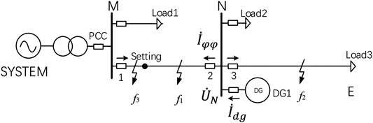
FIGURE 1. Diagram of the distribution grid, connected with the IIDG.
In Eq. 7, 8,
In Eq. 7, let:
Therefore, (7) can be simplified as follows:
By introducing (6), (8), and (10) into (5), we can get the following result:
where
By introducing (9) into
It is observed from Eq. 13 that after neglecting the influence of the phase angle difference of
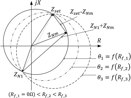
FIGURE 2. Adaptive characteristics with the fault resistance of positive sequence voltage fault component polarized impedance relay when forward fault occurs.
Therefore, the operation characteristics of Eq. 12 can be expressed as follows:
The dynamic adjustment of the operation characteristics can adaptively change the protection zone, and the ability of the protection criterion to overcome the influence of the fault resistance is significantly improved.
As can be seen from Figure. 2, when the forward fault occurs the operation characteristic contains the installation position, that is, the origin of coordinates. The positive sequence fault component, as a polarization quantity, can avoid the influence of the dead zone caused by the low positive sequence voltage of metallic fault at the near end of protection installation. Compared with the traditional positive sequence voltage polarization impedance relay, this characteristic is also suitable for a three-phase short circuit in the near zone and has a wide range of adaptability.
In the case of the phase-to-phase short circuit at point
Here
In(15)
The pre-fault positive sequence voltage
By introducing (15) and (17) into Eq. 5, we can get the following result:
Eq. 18 is further simplified:
By introducing Eq. 16 into
With the increase of the transition resistance, the operation characteristics will be deflected in the angle of
Figure. 3 shows the operation characteristics of positive sequence fault component polarization impedance relay under the reverse direction fault. The influence of the fault resistance makes the protection zone deviate. However, when the fault occurs in the opposite direction, the measured impedance falls in quadrants III and IV which is far away from the operating area of the throw-up circle, so the characteristic still has explicit directionality.
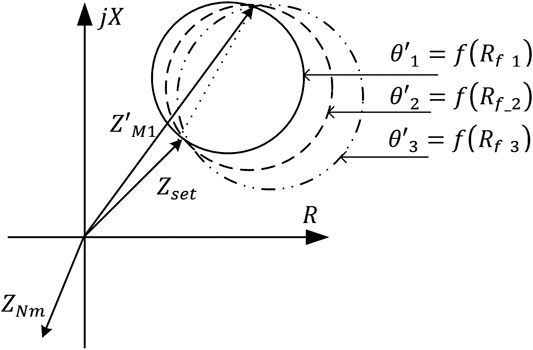
FIGURE 3. Adaptive characteristics with the fault resistance of fault component positive sequence voltage polarized impedance relay when backward fault occurs.
As this is affected by the fault resistance in a short transmission line, relay over-reaching problems may exist. In coordination with the operation characteristics shown in Eq. 5, a reactance line C2 with downward deflection angle is added at the end of the protection range, as shown in Eq. 22:
The "AND" logic is composed of two characteristics of Eq. 5, 22, that is,
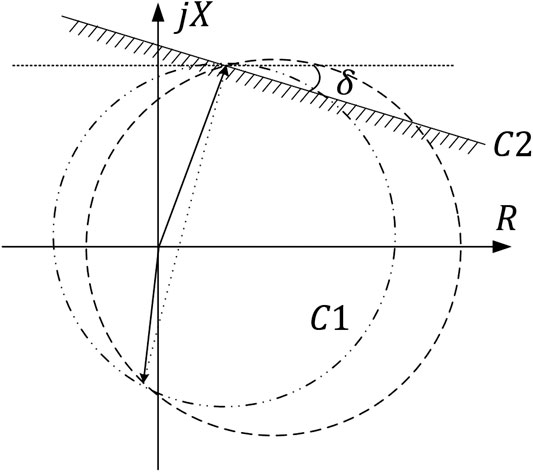
FIGURE 4. Composite adaptive characteristics of the positive sequence voltage fault component polarized impedance relay when forward fault occurs.
Case Study
The proposed protection principle is verified and analyzed by using a typical distribution grid simulation test system with the IIDG connected as shown in Figure. 1. The system voltage level is 10kV, the transformer capacity is 10MVA, and the neutral point is grounded by Petersen Coil. The length of the overhead line MN in the distribution grid is 5km, the parameter is
In the simulation system shown in Figure 1, the point of common coupling (PCC) is closed, the IIDG is connected to the grid, and protection 2 is at the receiving end. When the protected line is 2.5 km away from the protection installation, a short circuit between the BC phase with a 2Ω fault resistance occurs. The trajectory of the protection measurement impedance 20ms after the fault occurs is shown in Figure 5. The operation characteristic of C1 shown in Eq. 5 fluctuates about
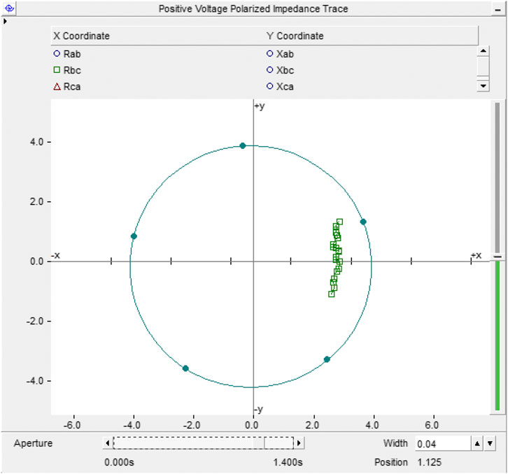
FIGURE 5. When the protection is at the receiving end, the PCC is connected to the grid. The measured impedance trajectory and operation characteristics of the positive sequence voltage fault component polarized impedance relay at a BC phase fault with a fault resistance (2Ω) at 2.5 km forward.
Figure 6 shows the track of measured impedance when the protection is at the sending end after the PCC is disconnected and the same fault occurs. At the same time,
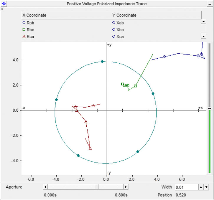
FIGURE 6. When the protection is at the sending end, the PCC is disconnected from the grid. The measured impedance trajectory and operation characteristics of the positive sequence voltage fault component polarized impedance relay at a BC phase fault with a fault resistance (2Ω) at 2.5 km forward.
Figure 7 shows the operation trajectory of impedance measurement when the protection is at the receiving end and the close-in fault occurs in the opposite direction. When
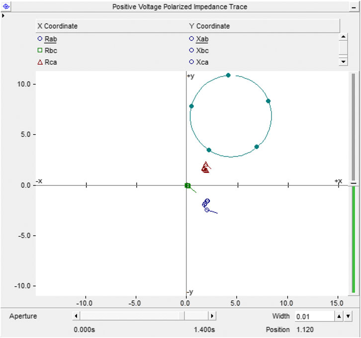
FIGURE 7. When the protection is at the receiving end, the PCC is connected to the grid. The measured impedance trajectory and operation characteristics of the positive sequence voltage fault component polarized impedance relay at a BC phase metallic fault 0.1 km backward.
For the other faults, according to the opening and closing of the PCC switch, various fault types of protection 2 under the sending end and receiving end are simulated respectively. The simulation results of the two-phase short circuit are shown in Table 1 and Table 2. The simulation results of the three-phase short-circuit fault are the same as that of the phase-to-phase short-circuit fault. For the sake of brevity, not all are listed here.

TABLE 1. Simulation Result of phase BC fault occurring under the protection operation in receiving end.
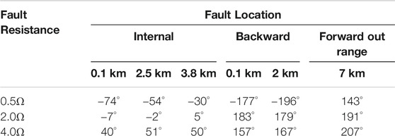
TABLE 2. Simulation Result of Phase-to-Phase fault occurring under the protection operation in sending end.
For common faults, Table 1 and Table 2 show that the protection can normally clear various types of faults. However, when the protection system operates at the receiving end, the system impedance is far less than the distribution composite equivalent impedance including the IIDG. Due to the strong effect of the opposite side system and the short distribution line, when the phase to phase short circuit with the transition resistance of 4.0 Ω occurs, the operating condition of the protection criterion cannot be satisfied. In this case, the selectivity of operation can only be ensured by the backup protection or the protection principle based on both-end information.
Implementation of Distribution Grid Protection based on specialized SoC for Power System
To make the proposed protection principle applicable, a 35 kV/10kV distance protection based on the specialized multi-core heterogeneous SoC (FUXI-M) for the power system was developed. The chip fully considers the requirements of high-efficiency parallel processing units of a power-specific algorithm, power consumption, and application economy. It combines the Discrete Fourier algorithm, sequence quantities calculation, filtering, interpolation, and the other calculation tasks originally implemented by general-purpose CPUs, as well as communication encoding and decoding. General tasks such as security encryption are integrated into an independent core on-chip for realizing power-specific algorithms, forming a power-specific multi-core heterogeneous SoC chip as shown in Figure 8. The functional calculation of distribution grid protection is realized by using the parallel calculation of independent hardware units in the chip, which greatly improves the execution efficiency of the algorithm.
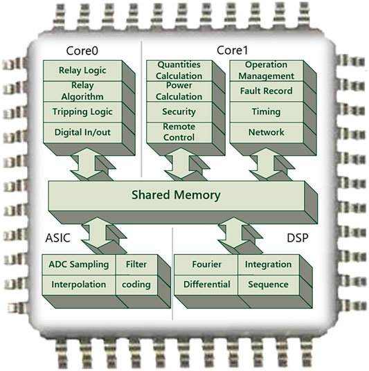
FIGURE 8. Schematic diagram of specialized multi-core heterogeneous SoC chip for power system.
According to the positive sequence voltage fault component polarization impedance criterion proposed in this paper, it constitutes three-zone distance protection adapted to the operational requirements of the distribution grid. Since the primary computing architecture has been integrated into parallel processing in independent ASIC core and signal processing co-processors (DSP), the distance protection program and logic calculation operating at Core 0 is simple and efficient. As shown in Figure 9, the program flow is divided into three main threads for execution. The protection and logic threads only need to maintain simple sequential execution. The thread processing and program logic structure are greatly simplified, and the execution time is also significantly reduced.
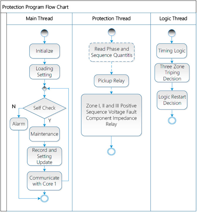
FIGURE 9. Flow chart of distance protection program running on core0 of SoC chip for power system.
The developed protection device is shown in Figure 10. It was put into trial operation at a 110kV Ruiyan substation in Foshan, China in early 2019. During several external fault tests, no maloperation of external fault was observed.
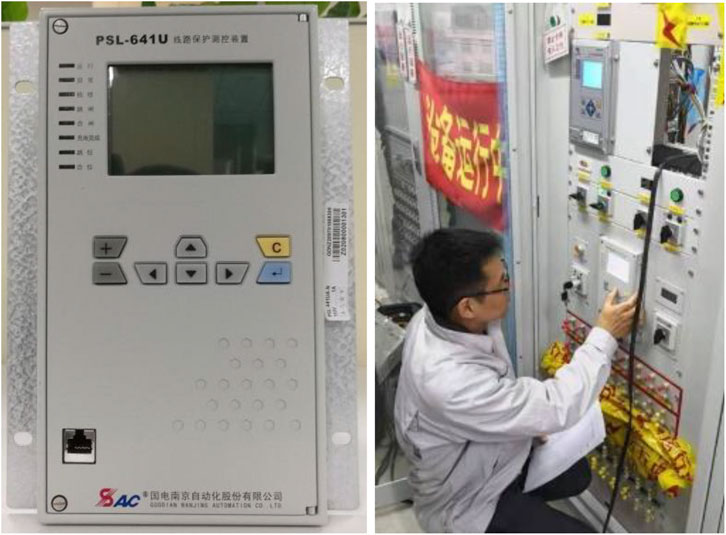
FIGURE 10. The photos of distance protection device based on SoC chip special for power system and industrial field testing.
Conclusion
This article has analyzed the impact of the IIDG on the protection system of the distribution grid. For the protection system installed on the near-IIDG side, due to the LVRT control characteristics of the IIDG, the current fed to the fault point was closely related to the busbar voltage of the IIDG, and the maximum short-circuit current was also limited to a low level. The negative sequence current suppression control strategy also changes the transient characteristics measured by the protection scheme. This makes the application of traditional overcurrent protection difficult and the requirements of selectivity and sensitivity can no longer be met by the legacy protection schemes in the distribution grid.
Based on the positive sequence voltage polarization impedance criterion, this paper proposes an impedance criterion based on positive sequence voltage fault component polarization, which can adaptively follow the fault resistance variation. Verification of these findings with a simulation showed that the criterion was less affected by the fault response characteristics of the IIDG under fault conditions. A distribution grid protection device, based on the specialized SoC for a power system, was developed and a trial-run on the industrial site has been carried out. The operating performance of the new protection device meets the requirements of the distribution grid with the IIDG. The proposed protection scheme and the implementation has broad application opportunities in the distribution grid with the IIDG.
Data Availability Statement
The raw data supporting the conclusions of this article will be made available by the authors, without undue reservation.
Ethics Statement
Written informed consent was obtained from the individual for the publication of any potentially identifiable images or data included in this article.
Author Contributions
PL conceived of the proposed idea and supervised the work. WX performed the device development. XY planned and carried out the simulations. XZ carried out the experiments. LL verified the analytical methods. QY contributed to the interpretation of the results. WC developed the theory and took the lead in writing the manuscript. All authors provided critical feedback and helped shape the research, analysis and manuscript.
Funding
This work was supported by the National Key R&D Program of China under Grant 2018YFB0904900, 2018YFB0904902.
Conflict of Interest
PL, WX, and LL was employed by the CSG, Guangzhou, China. QY was employed by the Sifang Automation Co., Ltd., Beijing, China.
The remaining authors declare that the research was conducted in the absence of any commercial or financial relationships that could be construed as a potential conflict of interest.
Supplementary Material
The Supplementary Material for this article can be found online at: https://www.frontiersin.org/articles/10.3389/fenrg.2020.614292/full#supplementary-material.
References
Chen, G., Liu, Y., and Yang, Q. (2020). Impedance differential protection for active distribution network. IEEE Transactions on Power Delivery 35, 25–36. doi:10.1109/TPWRD.2019.2919142
Fang, Y., Jia, K., Yang, Z., Li, Y., and Bi, T. (2019). Impact of inverter-interfaced renewable energy generators on distance protection and an improved scheme. IEEE Transactions on Industrial Electronics 66, 7078–7088. doi:10.1109/TIE.2018.2873521
Han, B., Li, H., Wang, G., Zeng, D., and Liang, Y. (2018). A Virtual multi-terminal current differential protection scheme for distribution networks with inverter-interfaced distributed generators. IEEE Transactions on Smart Grid 9, 5418–7088. doi:10.1109/TSG.2017.2749450
Han, B., Wang, G., Li, H., and Zeng, D. (2016). “An improved pilot protection for distribution network with inverter-interfaced distributed generations,” in 2016 IEEE PES asia-pacific power and energy engineering conference (APPEEC), Xi'an, October 25–28, 2016. doi:10.1109/APPEEC.2016.7779949
Huang, W., Nengling, T., Zheng, X., Fan, C., Yang, X., and Kirby, B. J. (2014). An impedance protection scheme for Feeders of active distribution networks. IEEE Transactions on Power Delivery 29, 1591–1602. doi:10.1109/TPWRD.2014.2322866
Jia, K., Gu, C., Xuan, Z., Li, L., and Lin, Y. (2017). Fault Characteristics analysis and line protection design within a large-scale photovoltaic power plant. IEEE Transactions on Smart Grid.9, 4099–4108. doi:10.1109/TSG.2017.2648879
Jia, K., Yang, Z., Fang, Y., Tianshu, B., and Sumner, M. (2019). Influence of inverter-interfaced renewable energy generators on directional relay and an improved scheme. IEEE Transactions on Power Electronics 34, 11843–11855. doi:10.1109/TPEL.2019.2904715
Li, Q., Yong-jun, Z., Wei-peng, Y., and Feng, L. (2012). “A study on influence of wind power on positive sequence voltage polarized impedance relay,” in 2012 Power Engineering and Automation Conference, Wuhan, September 18–20, 2012. doi:10.1109/PEAM.2012.6612485
Li, Y., Jia, K., Bi, T., Yan, R., Li, W., and Liu, B. (2017). “Analysis of line current differential protection considering inverter-interfaced renewable energy power plants,” in 2017 IEEE PES Innovative Smart Grid Technologies Conference Europe (ISGT-Europe), Torino, September 26–28, 2017. doi:10.1109/ISGTEurope.2017.8260157
Li, W., He, J., Zhang, D., and Zhang, Q. (2017). Directional pilot protection based on fault current for distribution network with Distributed Generation (DG). The Journal of Engineering 2017, 1327–1331. doi:10.1049/joe.2017.0546
Li, P., Kong, X., Han, J., Zhang, Z., and Yin, X. (2019). “Research on low voltage ride through strategy and fault calculation equivalent model of power electronic transformer,” in 2019 4th international conference on intelligent green building and Smart grid (IGBSG), Hubei, Yichang, China. September 6–9, 2010. doi:10.1109/IGBSG.2019.8886267
Li, B., De-shu, C., Xiang-gen, Y., Yi, Z., and Yu-feng, H. (2003). Study on the new adaptive MHO relay. Proceedings of the CSEE 23, 80–83.
Mahamedi, B., and Fletcher, J. E. (2019). Trends in the protection of inverter-based microgrids. IET Generation, Transmission and Distribution 13, 4511–4522. doi:10.1049/iet-gtd.2019.0808
Singh, M., and Agrawal, A. (2019). Voltage–current–time inverse-based protection coordination of photovoltaic power systems. IET Generation, Transmission and Distribution 13, 794–804. doi:10.1049/iet-gtd.2018.6143
Song, G., Wang, X., Chang, Z., Tang, J., and Liu, P. (2016). “A novel protection method of collecting power lines in PMSG wind farm,” in 2016 IEEE PES asia-pacific power and energy engineering conference (APPEEC), Xi'an, October 25–28, 2016. doi:10.1109/APPEEC.2016.7779854
Tang, J., Song, G., Wang, X., and Chang, W. (2016). “A novel directional relay applicable to power system with wind farms,” in 2016 IEEE PES asia-pacific power and energy engineering conference (APPEEC), Xi'an, October 25–28, 2016. doi:10.1109/APPEEC.2016.7779860
Telukunta, V., Pradhan, J., Agarwal, A., Singh, M., and Srivani, S. G. (2017). Protection challenges under bulk penetration of renewable energy resources in power systems: a review. CSEE Journal of Power and Energy Systems 3, 365–379. doi:10.17775/CSEEJPES.2017.00030
Yang, J., Zhou, C., and Zou, G. (2018). “A protection scheme based on positive sequence fault component for active distribution networks,” in 2018 2nd IEEE Conference on Energy Internet and Energy System Integration (EI2), Beijing, October 20–22, 2018. doi:10.1109/EI2.2018.8582469
Yang, Z., Jia, K., Fang, Y., Zhu, Z., Yang, B., and Bi, T. (2020). High-frequency Fault Component-based distance protection for large renewable power plants. IEEE Transactions on Power Electronics 35, 10352–10362. doi:10.1109/TPEL.2020.2978266
Yang, H., Zhang, Z., Yin, X., Xiao, F., Qi, X., and Ye, Y. (2016). “Study of the collector-line-current-protection setting in centralized accessed double-fed wind farms,” in 2016 IEEE Power and Energy Society General Meeting (PESGM), Boston, MA, October 20–22, 2018. doi:10.1109/PESGM.2016.7741664
Zhang, F., Mu, L., and Guo, W. (2019). An integrated wide-area protection scheme for active distribution networks based on fault components principle. IEEE Transactions on Smart Grid 10, 392–402. doi:10.1109/TSG.2017.2741060
Zhou, C., Zou, G., Yang, J., and Lu, X. (2019). “Principle of pilot protection based on positive sequence fault component in distribution networks with inverter-interfaced distributed generators,” in 2019 IEEE PES GTD grand international conference and exposition asia (GTD asia), Bangkok, Thailand, March 19–23, 2019. doi:10.1109/GTDAsia.2019.8716011
Keywords: distribution grid, inverter interfaced distributed generation, low voltage ride through, positive sequence voltage polarization, system-on-chip based protection
Citation: Li P, Xi W, Yin X, Zeng X, Li L, Yang Q and Chen W (2020) A Specialized System-on-Chip Based Distance Protection for Distribution Grids with Inverter Interfaced Distributed Generation. Front. Energy Res. 8:614292. doi: 10.3389/fenrg.2020.614292
Received: 05 October 2020; Accepted: 24 November 2020;
Published: 22 December 2020.
Edited by:
Yang Mi, Shanghai University of Electric Power, ChinaReviewed by:
Tai Nengling, Shanghai Jiao Tong University, ChinaTao Lin, Wuhan University, China
Xiaohua Li, South China University of Technology, China
Copyright © 2020 LI, XI, YIN, ZENG, LI, YANG and Chen. This is an open-access article distributed under the terms of the Creative Commons Attribution License (CC BY). The use, distribution or reproduction in other forums is permitted, provided the original author(s) and the copyright owner(s) are credited and that the original publication in this journal is cited, in accordance with accepted academic practice. No use, distribution or reproduction is permitted which does not comply with these terms.
*Correspondence: Wei Chen, d2VpY2hlbkBodXN0LmVkdS5jbg==