 Qunhai Huo
 Wenyong Wang1,2
- 1Institute of Electrical Engineering, Chinese Academy of Sciences, Beijing, China
- 2University of Chinese Academy of Sciences, Beijing, China
- 3Electric Power Research Institute of Guangdong Power Grid Corporation, Guangdong, China
The current large-scale access to distributed power and the rapid growth of electric vehicles are seriously affecting the reliability of distribution networks. The new multi-station fusion technology based on the flexible interconnection of the distribution network can effectively solve this problem. In this study, we design a multi-purpose station and a multi-function device using a soft normally open point (SOP). A new multi-station integration topology and a coordinated control strategy are developed using an active power signal (APS) and an energy management system (EMS). The coordinated control strategy involves sending out the corresponding operation mode command after the EMS receives the superior instruction or the APS of the local system and coordinating the operation mode of the SOP, energy storage DC/DC converter, and photovoltaic DC/DC converter, thereby ensuring stable and efficient operation of the multi-station fusion system. Finally, two typical cases are simulated to verify the feasibility and effectiveness of the proposed topology and control strategy.
Introduction
With the acceleration in the construction of the 5G infrastructure and the rapid development of the intelligent manufacturing industry (Giampieri et al., 2020), the quality requirements of the power of the distribution network are becoming increasingly stringent. Furthermore, the urban power grid is struggling to maintain pace with the rapid development of electric vehicles (Cha et al., 2020) and distributed generation (DG) (Ma et al., 2019), and problems such as unreasonable power grid structure are more becoming prominent (Abu-Elzait and Parkin, 2019). With the continuous economic growth, the demand for power continues to grow rapidly. The fluctuation of the power supplied by DG and the irregular large-scale access of electric vehicles to the distribution network causes the power flow to fluctuate (Tang et al., 2019). The high penetration access of DG (Chang and Chinh, 2020) may lead to providing excessive power to some equipment in the distribution network and even cause maloperation of such equipment. Therefore, it is difficult to satisfy the power quality and power supply reliability requirements of users.
Multi-station integration based on the flexible interconnection of the distribution network can solve the above problems. Several novel flexible power electronic devices can be applied to improve the controllability and flexibility of the power system (Cong et al., 2019; Long et al., 2016; Ouyang et al., 2020). Compared with the traditional distribution network, which relies on the sectionalized switch and tie switch (TS), the novel multi-station distribution network uses soft partition achieved by connecting soft normally open point. During the normal operation of the system, the power of an SOP can be regulated between different interconnected distribution areas to realize mutual power flow and promote the global optimization of the energy under the steady-state condition (Li et al., 2018; Bai et al., 2018). Compared to traditional TS, SOP can enhance the controllability and improve the power quality of the distribution network, and improve the reliability of the power supply system.
On the research progress of multi-station fusion, reference (Xu et al., 2019) analyzed the optimal design and operation of an energy storage station under multi-station integration and reported the optimal design capacity and optimal operation strategy of the storage station based on multi-station integration. Reference (Zhang et al., 2019) discussed the connotation and characteristics of multi-station integration and a business model for multi-station integration based on the operation mode and business system. They verified the feasibility of the proposed business model with project examples. Reference (Wang et al., 2020) built a three in one DC power supply system based on an energy storage station, data center, and substation and compared it with the traditional high-voltage direct current system. However, the above literature is limited to the simple combination of multiple stations. The complementarity and integration of multiple function stations are not strong, the function of each function station is not fully played, the reliability of the system can be further strengthened, and the theoretical analysis of multi-station fusion and the innovation of topology structure is insufficient. At present, there are not enough research results in the realization of high-power supply reliability, power flow transfer and multi-purpose of one station.
In this paper, we propose a topology of the multi-station integration structure with a single DC bus based on SOP. The load is supplied hierarchically according to the demand. The issues of unidirectional flow and complex device coordinated control in traditional energy distribution networks are overcome through the coordinated control of SOP devices and other converter devices in the system. The coordinated control allows the power flow control among feeders and the highly reliable provision of sensitive loads in the system and promotes the overall optimization of the distribution network energy. The major contributions of this paper are as follows:
(1) From the topology and framework perspectives of power grids, a highly integrated multi-station system fusion topology based on the SOP is created. This results in an in-depth application of the SOP in the multi-station fusion system, and thus diverse load supplies with high-level power quality are achieved.
(2) The “APS plus EMS” coordinated control strategy is proposed, and the autonomous operation of the local system can be divided into three working modes, and each mode can be further divided into different sub-modes depending on the state of the system. These efforts can improve the flexibility of the system operation and the reliability of power supply for sensitive loads.
(3) The effectiveness of the proposed multi-station system topology and control strategies is verified through two case studies.
The remainder of this paper is organized as follows. The topology of multi-station integration is proposed in Proposed Topology of Multi-Station Integration. The coordinated control strategy of multi-station integration is established in Coordinated control strategy of multi-station integration. Case studies are presented in Simulation Analysis of Different Cases. Conclusion is drawn in Conclusion.
Proposed Topology of Multi-Station Integration
Different from the traditional AC/DC distribution network, in this study we use SOP as the key equipment of multi-station integration systems, which can solve the problems of the AC/DC distribution network by implementing the two-end power supply. SOP can respond to the running state of the system in real-time and optimize the power flow distribution of the system and are promising to meet the requirements of future flexible distribution networks for primary flexible equipment (Ji et al., 2017; Liang et al., 2018; Li et al., 2019). Figure 1 shows the proposed multi-station integration topology with an SOP. The system is mainly composed of an AC power grid unit, energy management system (EMS), SOP, energy storage station, data center station, photovoltaic power station, 5G station, AC/DC load with different sensitivity levels, and electric vehicle charging station.
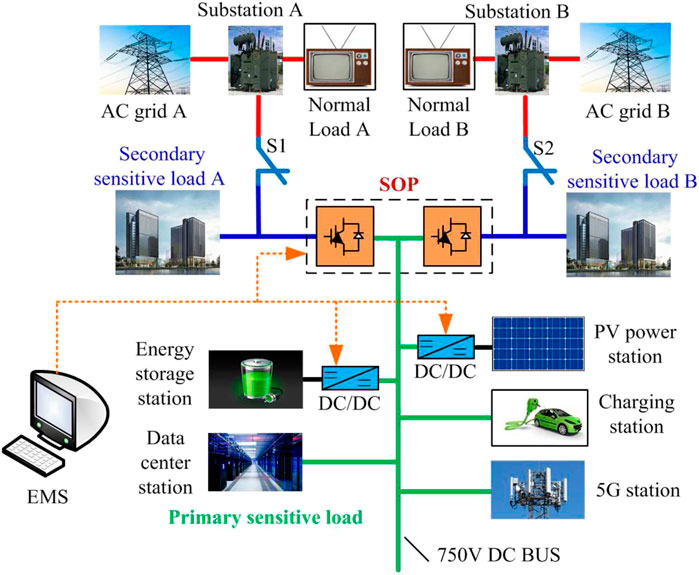
FIGURE 1. Multi-station integration topology.
The proposed multi-station integration system is significantly more compact than the traditional hybrid AC/DC microgrid. Complementary function integration can achieve hierarchical power supply and overall performance improvement. The integration of the energy flow, information flow, and data flow in the system can improve the comprehensive utilization rate of resources. Furthermore, the multi-station integration system can achieve multi-purpose of one station and multi-function of one device and provides positive interaction and mutual benefits to power/energy suppliers, equipment providers, and users. The construction of multi-station integration systems requires full consideration of various factors, including investment optimization, land comprehensive utilization rate, energy price, power supply reliability, power quality, consumption of green energy, and comprehensive energy service.
The multi-station integration in one distribution system has changed the traditional mode of the AC/DC hybrid distribution network. In this system, the steps of generation, network load, and storage of power are highly integrated; the energy flow, information flow, and data flow are integrated, providing higher power supply reliability. Different sensitive loads make it easier to perform the hierarchical power supply function and significantly increase the comprehensive efficiency of the power grid. The power flow distribution can be flexibly and dynamically adjusted depending on the load conditions, equipment status, and other information, to adapt the access of plug-and-play loads, such as distributed power supplies and electric vehicles, to the distribution network. This can more efficiently promote the integration of the energy supply, distribution, and service, and balance the benefits to users and providers.
In the proposed topology, the SOP is used as an interconnection between two distribution feeders, and the distributed power supply, electric vehicle charging station, and 5G station are connected at the SOP DC terminal. To guarantee the uninterrupted power supply of important loads and realize the peak shaving and valley filling of the system in case of a fault, the DC terminal of the SOP is connected to the energy storage station. Moreover, different sensitive loads can be reasonably configured in the multi-station system, which enables the hierarchical power supply function and highly reliable power supply. The power supply quality of a single DC bus is the highest; here, the loads are defined as primary sensitive load, and the loads on the two sides of the SOP are defined as secondary sensitive load; the load at the substation is defined as the normal load. The optimal configuration of the hierarchical power supply can provide high quality power with low costs.
The proposed multi-station integration topology fully utilizes the DC bus of the SOP to facilitate access to distributed power, electric vehicles, and other equipment. However, the stability of this topology is affected when integrating multiple function stations. The control stability of the DC bus voltage is the basis for the stable operation of the multi-station integration system.
Coordinated control strategy of multi-station integration
The system control strategy is shown in Figure 2. The SOP described in this paper consists of back-to-back voltage source converters (VSCs). VSC1 and VSC2 of SOP can run in P-Q mode, V-f mode and Vdc-Q mode. The control objectives of the two VSCs of the SOP would be changed according to actual situations to realize the real-time control of voltage and power. One of the functions of the FMSS in the multi-station integration system is to transfer active power of the AC power grid and balance the load on both sides of the FMSS. When AC fault occurs, the energy is exchanged with the DC bus through the bidirectional DC/DC converter, and for the battery the three working modes switch according to the power balance in the system.
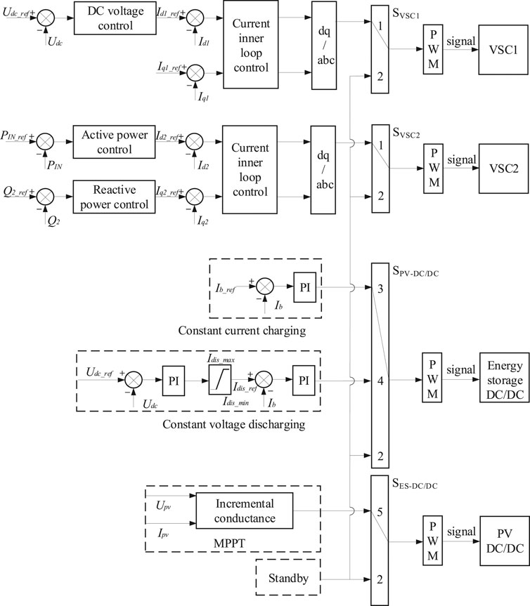
FIGURE 2. The block diagram of system control strategy.
The photovoltaic DC/DC converter transfers the maximum power in the grid-connected mode. This can be achieved using the maximum power point tracking (MPPT) control technology or by switching to the idle mode to terminate the output power. For the MPPT control of the photovoltaic DC/DC converter, we use the conductance increment method to determine the change in the direction of voltage by comparing the instantaneous value of the current output conductance and the change in conductance. According to the power voltage curve of the photovoltaic cell, the extreme value is calculated.
Where PIN and PIN_ref are active power and its reference flowing into the SOP respectively, Q2 and Q2_ref are reactive power and the reference flowing from the SOP respectively, Udc is the voltage value of DC bus, Udc_ref is control command voltage of SOP DC bus or energy storage, Id1, Iq1, Id2, Iq2,Id1_ref, Iq1_ref, Id2_ref, and Iq2_ref are axis components and reference values of AC currents of the VSC1 and VSC2, respectively, Idis_max and Idis_min are upper and lower limits of the battery discharge current respectively, Idis_ref is reference value of the current loop, Ib is the charge and discharge current of the battery, Ib_ref is reference value of charge and discharge current of the battery, IPV is output current of the photovoltaic array, and Upv is output voltage of the photovoltaic array.
The coordination between the stations essential for the stable operation and real-time power balance of the multi-station integration system. The stable operation of the SOP DC bus is affected by the various parts of the system, whose power status is closely related to the DC voltage. Accordingly, we adopt the “active power signal (APS) plus EMS” coordinated control strategy, as shown in Figure 3. This strategy allows the efficient power flow and stable control of the DC voltage and provides the maximum reliability of the power supply.
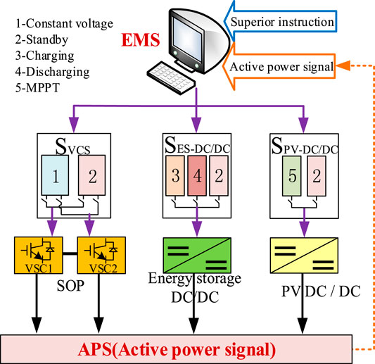
FIGURE 3. Coordination control strategy of multi-station integration.
We denote the output power of the distributed power supply as PDG; the power at the outlet side of the energy storage station as PES; the power consumed by the DC load as PDC_load; the power exchanged between the SOP DC bus and the AC grids A and B as PAB_ex, and the charging power of the DC bus of the energy storage station as PDC_bus. The total power of the SOP DC can be expressed as
When the voltage of the SOP DC bus changes, the energy change of the DC bus capacitor ΔEdc is
where Udc_ref is the rated value of the DC bus, and T0 is the system operation time.
From Eq. 2, Udc can be obtained as follows:
Equation 3 indicated that the DC bus voltage is affected by the power condition in the system. The stable DC bus voltage corresponds to the power balance of the system, so an unbalance in power flow leads to an abnormal bus voltage. Therefore, the power balance of the system can be achieved by controlling the DC bus voltage balance, thereby ensuring reliable and stable operation of the multi-station integration system. Therefore, it is necessary to adopt an appropriate converter control strategy to manage the energy flow of the SOP. With a reasonable distribution of the SOP and distributed power output and the coordination of the energy storage device and the grid-connected converter control, the power balance in the system can be achieved.
The total power balance of the multi-station integration system can also be expressed as follows:
where SOCmin and SOCmax are the lower and upper limits of the remaining capacity of the battery, respectively; Pmax_dischange and Pmax_change are the maximum discharging and charging power, respectively; Pmin_pv and Pmax_pv are the lower and upper limits of the output power of the photovoltaic power station, respectively; Pmin_exchange is the maximum allowable switching power.
The following power relations exist in the AC and DC buses of the multi-station integration system:
where POUT is the active powers flowing out of the SOP.
Equation 5 indicates that PIN and POUT change when the system operation state changes. For example, if one side of the AC power grid is overloaded and the other side of the AC power grid is lightly loaded, power is transferred from the lightly side to the overloaded loaded side, increasing PIN. When a fault occurs on one side of the AC power grid, the load in that side will be transferred through the SOP, increasing PIN and POUT. In a multi-station integration system, any power change will change the active power through the SOP. Therefore, we combine the APS and EMS to judge the current working mode through the APS flowing in or out of the SOP. APSs are considered as dispatching signals of the EMS, and the operation mode of the power electronic devices in the control system are coordinated through the superior signals received by the EMS and the APS of the local system.
The coordination control strategy relies on the EMS as the general control layer, which is responsible for receiving the dispatching instructions of the upper-level grid and the APS of the local system. The EMS judges the system operation status according to the instructions of the upper-level or the APS and sends out the corresponding work mode instructions to coordinate the operation modes of the SOP, energy storage DC/DC converter, and photovoltaic DC/DC converter. The EMS operates according to the dispatching instruction received from the upper-level grid to realize the effective energy and active power flows and reactive compensation between the systems. When the EMS system does not receive the dispatching instruction from the upper-level grid, it operates the local system autonomously. In the autonomous operation mode, the EMS sends the corresponding control mode command through the APS received. In this study, the APS threshold interval is set according to the corresponding value of the active power in different operating conditions; then, the EMS judges the operation mode of the system according to the APS value.
With the above coordination control strategy, the autonomous operation of the local system can be divided into three working mode types, and each working mode type can be divided into different sub-modes depending on the state of the system. In this paper, PIN_ref denotes the reference value of the active power flowing into the SOP under the ideal operation of the system (i.e., the AC load on the two sides is equal; the DC load is constant, and the photovoltaic power station outputs the maximum power). The reference value PIN is divided into different threshold intervals according to the three working modes. Among them, a0 and b0 are the reference coefficients (a0 ≥ 1 and b0 < 1) determined according to the actual state of the system.
Operation mode 1:
Operating mode 2:
Operating mode 3:
Simulation Analysis of Different Cases
We designed a simulation model of the multi-station integration system in MATLAB/Simulink to analyze the operation in the different modes. We assumed that the data center contains ten cabinets, with a total power of 40 kW. The maximum output power of photovoltaic station was set to 50 kW; the power of the two 5G stations was set to 10 kW, and different AC and DC loads were considered. Two different operating modes were simulated. The rationality of the above-mentioned multi-station integration topology structure and the correctness of its control strategy were verified. The relevant parameters of the simulation model are shown in Table 1.
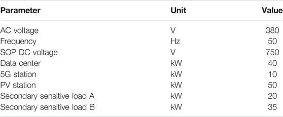
TABLE 1. System parameters.
Case 1
The simulation of case 1 verifies operating mode 1. To simplify the analysis, the photovoltaic and data center stations balance the power generation and energy supply and demand. Initially, the energy storage station is fully charged and operates in the standby mode; the photovoltaic station operates in the MPPT mode, and all the output power is supplied to the data center and 5G station. In AC grid A, the secondary sensitive load A is set to 20 kW, and the normal load A is set to 30 kW. In AC grid B, the secondary sensitive load B is set to 35 kW, and the normal load B is set to 55 kW. At 0.5 s, the SOP starts the power flow control.
As shown in Figure 4, before the power flow control of the SOP starts, the power from the AC power grid on the two sides is unbalanced. AC power grids A and B send 50 and 90 kW of active power, respectively. Half a second after the power flow control is started, the active power from the AC power grid on the two sides reaches the balance state after the short-term power flow regulation, reducing the line loss of the distribution network system and the transformer pressure of the feeder upstream.
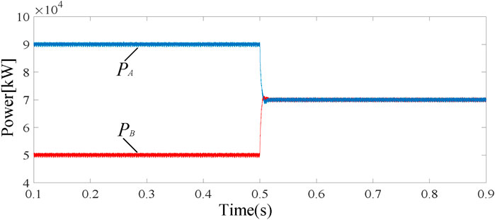
FIGURE 4. Active power of AC grids A and B.
The results show that in operation mode 1, the system has good dynamic response capability when the DC load changes suddenly, which can ensure the stability of the DC voltage and the transfer capability of the system power flow. After 0.4 s, a 50 kW DC load is added, and after 0.7 s, a 30 kW DC load is cut off. The simulation results are shown in Figure 5.
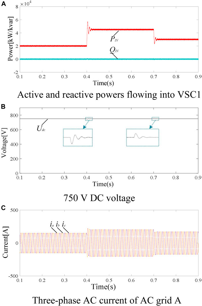
FIGURE 5. DC load fluctuation simulation results (A) Active and reactive powers flowing into VSC1 (B) 750 V DC voltage (C) Three-phase AC current of AC grid A.
As shown in Figure 5A, after a sudden increase of 50 kW in the DC load at 0.4 s, the active power flowing into VSC1 from AC grid A increases from 20 to 45 kW. After the 30 kW DC load is cut off at 0.7 s, the power flowing into VSC1 decreases by 15 kW. After a 0.02 s adjustment time, the system reaches a stable operation state. It can be seen from Figure 5B that the DC voltage of the SOP remains stable under the sudden changes in the load. In the dynamic response stage, the voltage fluctuation of the DC bus is within ±5 V, which ensures stable power transmission in the system. Figure 5C shows the current waveform of AC grid A.
It can be seen from the simulation results that the dynamic response of the system is perfect when the load changes suddenly, and it can track APS instructions accurately and quickly, so that the system operates in a stable state. Simulation results verify the effectiveness of the proposed topology and control strategy in mode 1.
Case 2
Case 2 verifies the sensitive load power supply capacity and the stability of the DC bus when one of the AC systems fails. In this case, the system switches from operation mode 1 to operation mode 2. To reflect the situation after the fault of AC grid B more intuitively, initially, the energy storage station is fully charged and operates in the standby mode. The photovoltaic station is in the MPPT mode, and all the output power is supplied to the data center and 5G station. The DC bus load is set as a 20 kW primary sensitive load. Loads of AC grid A are set as a 20 kW secondary sensitive load and a 30-kW normal load A. Loads of AC grid B are set as a 35 kW secondary sensitive load and 35 kW normal load. At 0.4 s, AC grid B fails, and the 35 kW normal load B is cut off. The secondary sensitive load B is maintained, and the fault is recovered at 0.7 s. The simulation results are shown in Figure 6.
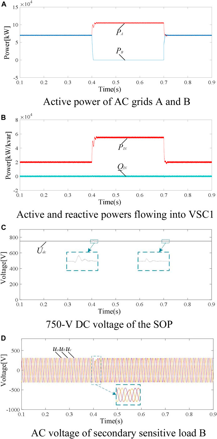
FIGURE 6. AC grid fault simulation results (A) Active power of AC grids A and B (B) Active and reactive powers flowing into VSC1 (C) 750 V DC voltage of the SOP (D) AC voltage of secondary sensitive load B.
As shown in Figure 6A, after the system fails at 0.4 s, the system supplies sensitive load power at the fault side through the SOP. As can be seen from Figure 6B, the power flowing into VSC1 increases from 20 to 55 kW in 0.4 s, which exceeds the preset upper limit. The EMS center judges the operation mode through the received APS and sends out the instruction of operation mode 2. The system cuts off the normal load B on the fault side, and the SOP carries out the power flow supply. When the system returns to the normal state in 0.7 s, it quickly stabilizes. Figure 6C shows that the DC voltage can remain stable when the AC system fails. In the dynamic response stage, the voltage fluctuation of the DC bus is within ±1%, ensuring the stable power transmission of the system. Figure 6D shows the voltage waveform of the secondary sensitive load B. When the fault occurs, the voltage fluctuates within a small range and quickly stabilizes after 0.02 ms.
It can be seen from the simulation results that when the system fails, because the SOP is used as the key equipment of the system, the system can still realize power flow transfer in case of failure, and maintains high reliability of power supply for sensitive loads. It can also perform good dynamic response characteristics of the system. The simulation results confirm that the multi-station integration topology and its control strategy described in this paper can effectively guarantee the stable operation of the system. The multi-station integration system has a highly reliable power supply capability for sensitive loads, such as those in data center stations.
Delaware Industrial Park in the United States has built as the first high-quality power park in the world, and has installed DVR, ASVC, transfer switch and other Distribution-Flexible AC Transmission Systems (D-FACTS) devices to realize the three-level power quality supply (Domijian et al., 2005). In this paper, only one SOP is used to realize the three-level power supply, and the comparison results show that the power quality level performed in this paper is better. In this paper, the response time is faster and the voltage fluctuation is smaller.
Conclusion
We proposed a topology structure of the multi-station integration system and simulated various scenarios that verified the feasibility of the coordinated control strategy. According to the multi-station integration topology, the “APS plus EMS” coordinated control strategy was proposed to achieve the stable operation of the system. We verified the rationality of the topological structure of the multi-station integration system. The topological structure fully guarantees the requirements of power supply reliability and system operation stability at different sensitive loads and can achieve effects of power flow in the system and power flow transfer under in the fault operation state.
In the future, we will investigate the capacity allocation of multi-station integration based on economic optimization. The construction of multi-station integration is of great importance to improve the operation and control ability of the distribution network. The results of this study are expected to promote the practical application of multi-station integration in the distribution network and accelerate the promotion and application of multi-station integration in the future intelligent distribution network.
Data Availability Statement
The original contributions presented in the study are included in the article/Supplementary material, further inquiries can be directed to the corresponding author.
Author Contributions
QH: Conceptualization, methodology, writing-original draft. WW: software, methodology; YY: methodology. MM: methodology. JY: validation. TW: Supervision.
Funding
This work is supported by the Strategic Priority Research Program of Chinese Academy of Sciences, Grant No. XDA 21050304 and Youth Innovation Promotion Association CAS (2017180).
Conflict of Interest
MM was employed by the company Electric Power Research Institute of Guangdong Power Grid.
The remaining authors declare that the research was conducted in the absence of any commercial or financial relationships that could be construed as a potential conflict of interest.
References
Abu-elzait, S., and Parkin, R. (2019). Economic and environmental advantages of renewable-based microgrids over conventional microgrids. 2019 IEEE green technologies conference (GreenTech), Lafayette, LA, United States, 3–6 April 2019. doi:10.1109/GreenTech.2019.8767146
Bai, L., Jiang, T., Li, F., Chen, H., and Li, X. (2018). Distributed energy storage planning in soft open point based active distribution networks incorporating network reconfiguration and DG reactive power capability. Appl. Energ. 210, 1082–1091. doi:10.1016/j.apenergy.2017.07.004
Cha, K.-S., Kim, D.-M., Jung, Y.-H., and Lim, M.-S. (2020). Wound field synchronous motor with hybrid circuit for neighborhood electric vehicle traction improving fuel economy. Appl. Energ. 263, 114618. doi:10.1016/j.apenergy.2020.114618
Chang, G. W., and Cong Chinh, N. (2020). Coyote optimization algorithm-based approach for strategic planning of photovoltaic distributed generation. IEEE Access 8, 36180–36190. doi:10.1109/access.2020.2975107
Cong, P., Tang, W., Lou, C., Zhang, B., and Zhang, X. (2019). Multi‐stage coordination optimisation control in hybrid AC/DC distribution network with high‐penetration renewables based on SOP and VSC. J. Eng. 2019, 2725–2731. doi:10.1049/joe.2018.8527
Domijian, A., Montenegro, A., Keri, A. J. F., and Mattern, K. E. (2005). Simulation study of the world’s first distributed premium power quality park. IEEE Trans. Power Deliv. 20 (2), 1483–1492. doi:10.1109/TPWRD.2004.839182
Giampieri, A., Ling-Chin, J., Ma, Z., Smallbone, A., and Roskilly, A. P. (2020). A review of the current automotive manufacturing practice from an energy perspective. Appl. Energ. 261, 114074. doi:10.1016/j.apenergy.2019.114074
Ji, H., Wang, C., Li, P., Zhao, J., Song, G., Ding, F., et al. (2017). An enhanced SOCP-based method for feeder load balancing using the multi-terminal soft open point in active distribution networks. Appl. Energ. 208, 986–995. doi:10.1016/j.apenergy.2017.09.051
Li, Y., Pei, X., Kang, Y., Lu, Y., Xu, F., and Wang., C. (2019). Voltage support strategy of SOP under fault circumstance. 2019 IEEE applied power electronics conference and exposition (APEC), Anaheim, CA, United States, 17–21 March 2019. doi:10.1109/APEC.2019.8722092
Li, Y., Pei, X., Chen, Z., Yang, M., Lyu, Z., and Wang, C. (2018). The steady-state and fault ride-through control strategies of soft normally open point in distribution Network. IEEE energy conversion congress and exposition (ECCE), Portland, OR, United States, 23-27 September 2018. doi:10.1109/ECCE.2018.8557615
Liang, H., Zhang, K., Li, S., Ge, L., Wang, Q., and Han, T. (2018). Allowable DG penetration capacity calculation of SOP-based flexible distribution network. 2018 China international conference on electricity distribution (CICED), Tianjin, China, 17-19 September 2018. doi:10.1109/CICED.2018.8592392
Long, C., Wu, J., Thomas, L., and Jenkins, N. (2016). Optimal operation of soft open points in medium voltage electrical distribution networks with distributed generation. Appl. Energ. 184, 427–437. doi:10.1016/j.apenergy.2016.10.031
Ma, C., Dasenbrock, J., Töbermann, J.-C., and Braun, M. (2019). A novel indicator for evaluation of the impact of distributed generations on the energy losses of low voltage distribution grids. Appl. Energ. 242, 674–683. doi:10.1016/j.apenergy.2019.03.090
Ouyang, S., Liu, J., Yang, Y., Chen, X., Song, S., and Wu, H. (2020). DC voltage control strategy of three-terminal medium-voltage power electronic transformer-based soft normally open points. IEEE Trans. Ind. Electron. 67 (5), 3684–3695. doi:10.1109/tie.2019.2922915
Tang, C., Liu, M., Dai, Y., Wang, Z., and Xie, M. (2019). Decentralized saddle-point dynamics solution for optimal power flow of distribution systems with multi-microgrids. Appl. Energ. 252, 113361. doi:10.1016/j.apenergy.2019.113361
Wang, B., Chen, Y., Liu, Y., Wang, H., Xu, L., Li, G., et al. (2020). Research on DC power supply system based on multi-station fusion. Digital Commun. World 2020 (2), 75–76. doi:10.3969/J.ISSN.1672-7274.2020.02.046
Xu, W., Cheng, H., Bai, Z., Miao, C., and Sun, F. (2019). Optimal design and operation of energy storage power station under multi-station fusion mode. Distribution and utilization 36 (11), 84–91. doi:10.19421/j.cnki.1006-6357.2019.11.12
Keywords: multi-station fusion, soft normally open point, active power signal, coordinated control strategy, multi-station integrated system, application of SOP
Citation: Huo Q, Wang W, Yang Y, Ma M, Yin J and Wei T (2021) Research on the Application of SOP in Multi-Station Integrated System. Front. Energy Res. 9:630234. doi: 10.3389/fenrg.2021.630234
Received: 17 November 2020; Accepted: 25 January 2021;
Published: 09 March 2021.
Edited by:
Hao Yu, Tianjin University, ChinaReviewed by:
Linquan Bai, University of North Carolina at Charlotte, United StatesZhongguan Wang, Tianjin University, China
Copyright © 2021 Huo, Wang, Yang, Ma, Yin and Wei. This is an open-access article distributed under the terms of the Creative Commons Attribution License (CC BY). The use, distribution or reproduction in other forums is permitted, provided the original author(s) and the copyright owner(s) are credited and that the original publication in this journal is cited, in accordance with accepted academic practice. No use, distribution or reproduction is permitted which does not comply with these terms.
*Correspondence: Qunhai Huo, aHVvcXVuaGFpQG1haWwuaWVlLmFjLmNu