 Hong Fan
 Weinan Yu
 Shiwei Xia
- 1State Key Laboratory of Alternate Electrical Power System with Renewable Energy Sources, North China Electric Power University, Beijing, China
- 2Department of Electrical Engineering, Shanghai University of Electric Power, Shanghai, China
As an emerging energy management technology, the DC nano-grid coordinates renewable energy sources output through demand-side management which would provide more options and flexibility for the dispatch of smart buildings and communities with high reliability and efficiency. In this context, this article has analyzed the structure and components of the DC nano-grid. The role and components in DC nano-grid are reviewed in this article. Then the crucial control technologies for the DC nano-grid in recent years are investigated from two aspects: local control and coordinated control, which contains control schemes such as voltage/current control technology, power-sharing technology and cooperative control technology. Different control strategies at various levels are compared and their application scenarios, advantages and disadvantages are also analyzed. The current research progress and challenges are summarized at the end of this article.
Introduction
Economic development is increasingly dependent on electricity, and the acceleration of urbanization and the development of new energy industries have put forward higher requirements for the power supply capacity and quality of distribution networks. According to the Global Status Report on Renewables 2019 (REN21 GSR-2019), renewable energy sources (RESs) have a share of more than 33% of the global power generation installed capacity. Photovoltaic (PV) accounts for 55%, wind 28% and hydro-electric 11% of the renewable power generating capacity worldwide (Murdock, 2019). The International Renewable Energy Agency (IRENA) predicts that the global RES share will reach 85% of the total energy supply by 2050 (Shafik et al., 2020). However, both photovoltaic arrays and wind turbines are affected by environmental factors such as temperature and weather, so distributed energy generation (DEG) mode is mostly used. The impact of small-scale DEGs on the grid is almost negligible. However, the large-scale deployment of DEGs will have negative effects on the grid operation due to the randomness and volatility of RESs. Therefore, the concept of Nano-grid (NG) is put forward, which is mainly composed of DEGs and local load. The concept of NG was firstly proposed by J. Ryan and R. Deuke in 2004 (Shahidehpour et al., 2017), which is defined as a small-scale independent DC power network operating. Its characteristics are 1) no more than 20 kW of power, 2) a space distance less than 5 km and 3) DC bus voltage about 400 V (Werth et al., 2015; Shahidehpour et al., 2017). NG is a bottom-up power supply structure (Lucia et al., 2013a; Nag et al., 2013). Subsequently, a grid-connected NG was proposed by Virginia Tech. This type of NG can be incorporated into a Micro-grid (MG) as a subsystem. In the later research, smart load and electric vehicles (EVs) were introduced successively. It is possible to build an ultra-low-voltage subsystem within NG. The typical voltage of it is much lower than the voltage level of traditional distribution networks, typically 48 V, 24 V or 12 V (Rodriguez-Diaz et al., 2016). For example, they can be used for low-power LED lighting or to connect loads with USB/Type-C interfaces.
The struggle between alternating current (AC) and direct current (DC) has been going on for more than a century and is also reflected in NG related research. Types of NG can be divided into DCNG, ACNG and AC-DC hybrid NG (AC/DCNG). When the DEGs and DC load are incorporated into the AC bus, the conversion process of current will reduce the electricity utilization (Fairley, 2012). The DC units in the DCNG can directly connect to the DC bus, thus improving the efficiency of power generation and consumption. DCNG has better stability than ACNG because the voltage level and the number of converters are reduced. AC/DCNG is a compromise choice, which has high energy efficiency and shows good adaptability to existing AC load (Patterson, 2012). Due to the increase in PV systems, fuel cells, energy storage units and DC loads, DCNG is becoming more and more prominent. At present, several pilot projects based on NG have been completed. For example, an NG was built on the seaside where the distribution grid cannot be connected (Wu et al., 2016). A new type of physical system was developed and implemented in the Power System Stability Laboratory (PSSL) of Sofia University of Technology to evaluate the control performance of the NG (Stanev et al., 2018). An AC/DCNG was established in Universidad del Valle as part of MG (Franco-Mejia et al., 2017). And an ETAP model is established to compare with the field operation (Shafik et al., 2020).
For a single DCNG, the control functions that the converter can achieve include: 1) power flow management, 2) maximum power output of RESs, 3) bus voltage adjustment, 4) inter-module current adjustment and 5) harmonic elimination. When the DCNGs are connected to form an MG, it needs to be coordinated and controlled through the communication system to realize energy management and interaction between each DCNG. The converter is the backbone of the DCNG, and almost all control functions need to be realized by converters (Saxena et al., 2016; Villalva et al., 2016; Saxena and Kulshreshtha, 2017). The performance and control method of the converter has a significant impact on the operation of the entire DCNG (Wu et al., 2017; Bagewadi et al., 2020). Local control is mainly used for voltage/current control and local power-sharing. It has the shortest response time. Coordinated control integrates the electrical information of each component, enhance the performance of power-sharing, and switch operating modes. The control strategies of DCNG are realized by the converter (Francés et al., 2018). For example, a converter connected to PV arrays can use the maximum power point tracking (MPPT) method to achieve the maximum power output of PV (Chaudhuri and Chaudhuri, 2013; Dogga et al., 2015). The inaccurate load share caused by the mismatch of the line impedance between multiple converters can be solved by master-slave control or droop control (Javaid et al., 2017a; Javaid et al., 2017b).
At present, there are relatively few research reviews on the control strategies of NG. Various analyses and black-box modeling strategies applied to smart DC micro/nano-grid are summarized in (Francés et al., 2018) for linear/nonlinear modeling techniques. Daniel. B etc. sorted out the definition of NG and given a concise definition of NG in (Daniel et al., 2017). Afterward, they summarized the control structure, technology and the corresponding hardware/platforms to realize the intelligent control of NG. Finally, the operation mode of interconnecting multiple NGs to form an MG was introduced, and the concepts of NG, MG and Pico-grid are distinguished in (Martin-Martínez et al., 2016) from four aspects of physical equipment, communication architecture, analytical intelligence and business model.
This paper reviewed the key local and coordinated control techniques by summarizes the principles and newest literature. The rest of this paper is organized as follows: The structure and components of DCNG were elaborated in Structure and Components of DCNG. In Control Strategies of DCNG, the principle and basis of the control strategies are introduced in advance, and then the specific control strategies are introduced. The future direction of the control technologies has prospected in Discussion of the Future Direction. Finally, Conclusion concludes the paper.
Structure and Components of DCNG
In DCNG, the DC bus integrates DEGs and loads. DEGs (photovoltaic, wind power, diesel generators, etc.) and energy storage systems (ESSs) connect to the DC bus through converters. Conventional DC loads are connected to the DC bus directly. Special DC loads need to connect to the DC bus through one-stage DC/DC converters. And before NG connects with other grid entities, a bidirectional DC/AC converter is needed. Figure 1 shows the entity and control structure of a DCNG.
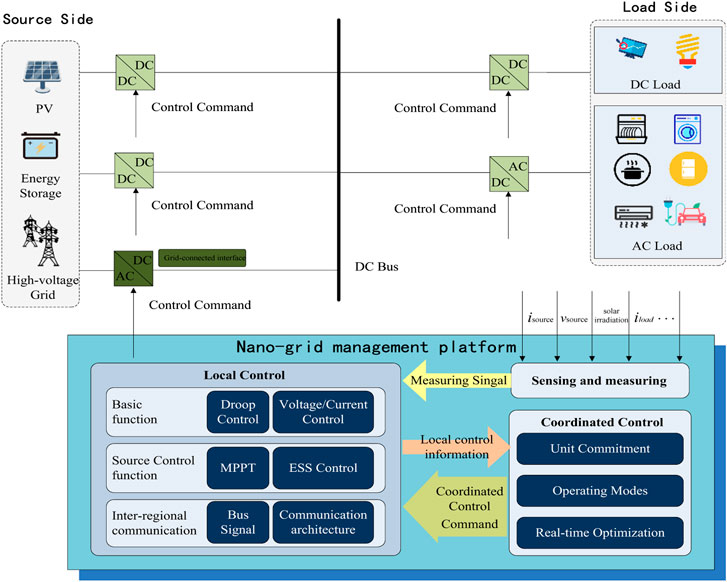
FIGURE 1. Physical and control structure of DCNG.
It can be seen from Figure 1 that DCNG contains the following components:
Nano-grid management platform: The NG management platform integrates local controllers, coordinated controllers, and measuring devices. The role of the NG management platform is to manage and optimize the use of energy. It can dispatch controllable resources within NG according to specific optimization algorithms and corresponding optimization indicators. The exchange of information between various control levels is also included. Some energy management techniques applied in NG have been summarized in (Bin Mohamad Saifuddin et al., 2019; Xia et al., 2019a; Bampoulas and Karlis, 2020; Salazar et al., 2020).
Sensing and measuring devices: These modules measure the physical quantities necessary for scheduling, such as temperature, light intensity, wind speed, and real-time power load. The utilities extract the characteristics of the user’s behavior and predict the future load using detailed information of data to achieve energy management better.
Converters: Used for grid connection of NGs, it can realize energy exchange between NG and MG. According to the variables used to adjust its state, the converter can be divided into Buck converters, Boost converters, Buck-Boost, and Cúk converters. Buck converter is simple and efficient. It gives the output voltage lower than the input voltage and provides a continuous output current (Goud and Gupta, 2020). The Buck converter requires a large capacitor to smoothen the discontinuous input current (Dursun and Gorgun., 2017). This converter also requires a higher gate side driver than the Boost converter. Boost converters provide output voltage higher than the input voltage. This converter has a continuous input current and a discontinuous output current (Adda et al., 2013). Boost converter requires a higher value of inductance compared to Buck converter. Buck-Boost and Cúk converters provide output voltage higher or lower than the input voltage with inverted polarity. Buck-Boost converter has more current ripples and lower efficiency than Buck and Boost converters (Elsayad et al., 2019).
Renewable energy sources: It is the main power source inside NG. The scenarios of source-side operation include 1) grid-connected mode; 2) island mode; 3) transition mode. Under the grid-connected mode, the DCNG bus voltage and active power are regulated by ESSs and the utility grid (Martin et al., 2018). The interface converter controls the power exchange between the DCNG and the utility grid. The RESs always operations at the maximum-power-point mode. In island mode, the DCNG bus voltage and active power balance are only controlled by ESSs (Azimi and Lotfifard, 2021). And a part of the RESs operations at the maximum-power-point mode. The transition is the switch between DCNG from grid-connected mode and island mode. The method that DCNG transitions from the grid-connected mode to the island mode is divided into 1) a transition process with non-uniform control strategies and 2) a transition process with uniform control strategies (Liu et al., 2018). The former refers to the operation in the current control mode in the grid-connected mode and the operation in the voltage control mode in the island mode. Some research schemes require that the DC line current be reduced to zero before switching to island mode (Kleftakis et al., 2017). While the other part of the research which allows the direct current not to be reduced to zero requires precise coordination of the compositions (Ochs et al., 2014). Otherwise, voltage spikes may occur during the switching process. The last refers to small-capacity DEGs operate in MPPT mode before and after transition, and larger DEGs operate in a voltage control mode (Yi et al., 2017). Before the DCNG transitions from the island mode to the grid-connected mode, it is necessary to synchronize the DCNG bus voltage with the public grid voltage. The method is divided into active synchronization and passive synchronization. The former refers to DEGs and ESSs actively cooperate to control the DC bus voltage to the system voltage (Vandoorn et al., 2013). And the last refers to connect to the grid when the system voltage is equal to the DC bus voltage (Cho et al., 2011).
Energy storage: Since the DCNG does not contain controllable power sources, the charging and discharging processes of energy storage units are the main way to achieve power balance. The power exchange between the ESS and the system has two components: high frequency (HF) and low frequency (LF) components (Tudu et al., 2019; Shen et al., 2020; Chang et al., 2018). Short-term power fluctuations caused by sudden changes in load or fluctuations of renewable energy sources are regarded as HF components. The slow power fluctuation caused by the normal behavior of the system is regarded as the LF component. The HF component needs to be processed by ESSs with a high power density and ramp rate. The LF component can be deal with by ESSs with high capacity. However, limited by current energy storage technology, no ESS showed in Table 1 can meet the above two requirements at the same time. An effective solution is to configure hybrid energy storage. A configure method of heterogeneous energy including electric-heat hybrid energy storage is proposed in Li et al. (2021). The authors use a scenario-based multi-level adaptive stochastic optimization method to deal with uncertainties from RESs, load, and environment. And the actual annual load growth is considered.
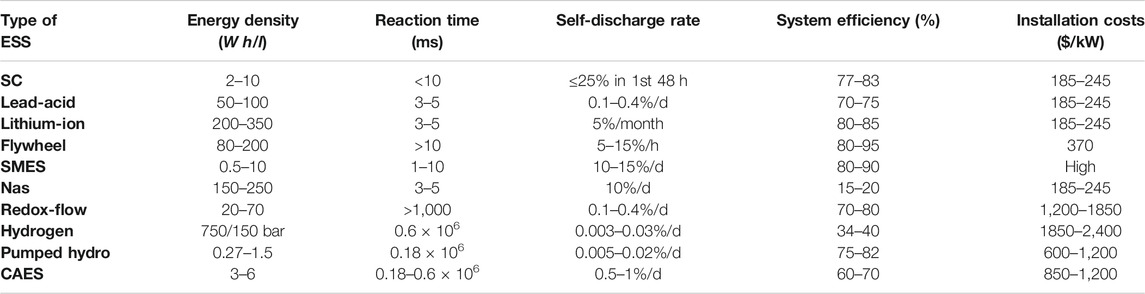
TABLE 1. Characteristics of different types of ESSs.
Smart loads: The smart load is different from the traditional load. It can adjust its power consumption level to respond to demand-side management and assist in peak shifting. The operating state
a) Uncontrollable loads: Such loads are entirely under the control of the users and cannot be dispatched. Such as entertainment facilities (televisions, computers, etc.). The possible operation of the uncontrollable loads at time t can be expressed as:
b) Light-control load: This load can operate at a certain ratio of rated power, and will not have a serious impact on the user's comfort. For example, the brightness of the lighting equipment can be appropriately reduced in the daytime. The possible operation of the light-control loads at time t can be expressed as:
c) Temperature-control load: Its operating state should be as close as possible to the reference value set by users. Otherwise, it may seriously affect the comfort level of users. It should be adjusted to the reference value as soon as possible after reducing its power in the necessary period. The typical is air conditioning.
d) Time-shifting load: The NG management platform can delay the power supply time to achieve peak load shifting before putting these devices into operation. Typical time-shifting load includes washing machines and dishwashers. However, it should note that the time-shifting loads cannot be interrupted once they are operated. The possible operation of the time-shifting load at time t can be expressed as:
e) Interruptible loads: It can be interrupted with a little cost, even during operation. Plug-in hybrid electric vehicles, for example.
A study in Tsao et al. (2021) addresses the real time-based demand response programs by leveraging blockchain technology to provide. A multi-objective mixed integer-linear programming model with three sustainable objectives (economy, environment, and society) is proposed. And a robust fuzzy multi-objective optimization approach is proposed to determine dynamic pricing decisions under uncertain demand. A multi-objective optimization model considering demand-side management was proposed in Rocha et al. (2021). The author considers real-time electricity prices, the priorities of equipment, operating cycles, and energy storage in demand-side management. This model uses three artificial intelligence algorithms, the support vector machine algorithm used to predict, the K-means algorithm used to fit the comfort of users, and the Elitist non-dominated sorting genetic algorithm II used to solve the model.
The RESs, grid-connected interfaces and smart loads are all objects that need to be controlled. These control methods will be explained in detail in Control Strategies of DCNG.
Control Strategies of DCNG
Local Control
The local control of NG is mainly for various internal devices. It controls the converter of each unit to keep the key indicators within an acceptable range. For the DCNG, there is no need to consider the frequency issue since there is no phase change of the current (Navarro-Rodríguez et al., 2019). The premise to ensure the power supply quality and system stability is the stable DC bus voltage (Ganesan et al., 2015). This requires multi-source coordination to maintain the DC bus voltage and power balance (Nguyen et al., 2020). Functions of the local control typically cover the following: 1) current and voltage control; 2) source-side control e.g., adjust output power for RESs; 3) load sharing, generally realized by master-slave control or droop control (Nasir et al., 2018). These control methods will be introduced in this Section.
Current/Voltage Control
Generally, the controller on the converter includes two modules: a voltage controller and a current controller. The voltage controller uses observations to estimate the global voltage and adjust the VSC voltage set point to achieve global voltage regulation. The current controller obtains the required filter inductor current and compares it with the adjacent converter, and uses this as a reference to modify the local converter parameters to realize load sharing.
The internal voltage and current control can be realized by the proportional-integral (PI) controller, proportional derivative (PD) controller, proportional integral derivative (PID) controller (Azab, 2017). The PI controller is easy to control, and because the PI controller introduces zero steady-state error, it has high robustness. The PD controller can improve the phase margin of the system. But it cannot eliminate the steady-state error like the PI controller. Therefore, the derivative term in the PD controller is usually replaced by a digital high-pass filter. The PID controller can be obtained by combining the PI controller and the PD controller (Murdianto et al., 2018). The performance of the PID controller depends on three parameters, proportional, integral, and derivative. The proportional coefficient has a direct influence on the response speed of the controller. And it can improve the control accuracy of the controlled system. The magnitude of the integral coefficient has a direct impact on the elimination speed of a static error. The differential coefficient improves the dynamic characteristics of the system. It suppresses the maximum dynamic deviation in the transition process and enhances the stability of the system.
Fuzzy control which an intelligent algorithm based on the knowledge base. The linguistic variables of the fuzzy controller refer to its input variables and output variables. They are variables given in the form of natural language rather than numerical values. Fuzzy control can deal with the uncertainty in DCNG. It can classify a variable to a certain category (or level) with the highest membership strength by setting a membership function. Figure 2. shows a typical membership function with five levels that Negative Big (NB), Negative Small (NS), Zero (Z), Positive Small (PS), and Positive Big (PB), respectively. Precision and processing time are proportional to the number of levels.
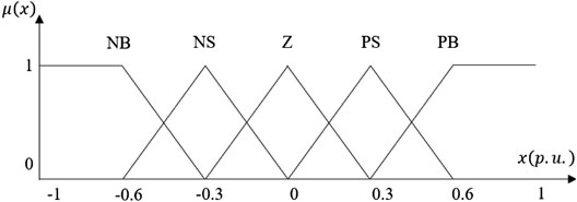
FIGURE 2. 5-level membership function of the inputs.
The membership degree of input x to each level i is assumed to be
and
These are called the Min rule and Max rule, respectively. Then the uncertain variables in DCNG are transformed into deterministic variables by these which are summarized based on the manual control experience of the operator. The defuzzification of fuzzy control uses the average weight for the rules and is denoted as follows:
The operator usually can only observe the total value or rate of change of the output variables. Therefore, the fuzzy controller generally converts the error or the rate of change for the error into a fuzzy variable firstly, then performs fuzzy inference and makes a fuzzy decision. The final deterministic variables are integrated into the PID controller as control parameters. For example, a new type of high-bandwidth fractional-order universal type-II fuzzy logic proportional-integral-derivative controller was applied in the secondary control layer in Mosayebi et al. (2020c), which can realize the rapid voltage regulation and state of charge (SOC) balance of DCNG. And in Mosayebi et al. (2020a), this fuzzy controller is further applied to the scene of multi-DCNG joint control.
Maximum Power Point Tracking Control
The maximum power point tracking (MPPT) control is usually applied to the converter connected to the RESs. It can always maintain the maximum power point (MPP) of the RESs. However, when the system absorbs overfill power, the bus voltage will increase and causes the entire system unstable (Vinnikov et al., 2020). Especially for power systems with low capacity and low voltage levels such as NG, fluctuations in the output power of RES can easily disrupt the local balance of the system. So MPPT is usually used in combination with droop control. That is, when the bus voltage rises to a prescribed extreme value, the control mode of the converter will switch from MPPT to droop control, adjusting the power output of RES and keep the bus voltage stable.
There are three basic types of MPPT. The first is the constant voltage (CV) method (Nasir et al., 2018). Its objective is to maintain the constant output voltage. When applied in photovoltaic arrays, the voltage at the maximum power point of solar cells under different lighting conditions is not much different and is approximately constant. This method has a large error, but it is easy to implement and has a low cost.
The second is the open-circuit voltage (OCV) method (Burmester et al., 2018). It is an improved method of CV method. The OCV method tracks the maximum power point by a reference voltage calculated based on Eq. 4
where
The last is the short circuit current (SCC) method (Rafiee and Sirouspour, 2018). It tracks the maximum power point by the maximum power current between 78% to 92% of the short circuit current (
This range is approximated by experiment. Like the OCV method, the SCC method also requires a short-circuit configuration in a certain period to measure the short-circuit current. This results in power loss and reduced efficiency. In addition, it cannot get the actual maximum power point because the maximum power point current is an approximate value.
The above is the basic theory of MPPT, and many artificial intelligence-based MPPT control methods have derived, such as PID-based MPPT controller (Maroufi et al., 2020), Fuzzy-Logic (FL) based MPPT controller (Veeramanikandan and Selvaperumal, 2020), Artificial-Neural-Networks (ANN) based MPPT controller (Al-Majidi et al., 2020), Genetic-Algorithms (GA) based MPPT controller (Hadji et al., 2018), and Particle-Swarm-Optimization (PSO) based MPPT controller (Merchaoui et al., 2020). The attributes that the P-V curve has a unique maximum power point located at the
The objective of PID-based MPPT control to annul the slope
The basic principles of fuzzy control have been introduced in Current/Voltage Control. And it is often used to optimize MPPT because of its advantages that no requires precise mathematical modeling and excellent ability to deal with nonlinear problems. The FL-based MPPT controller has two inputs and one output. The most frequently used inputs are the slope of the P-V curve and the change in the error as Eqs 7Eqs 8, respectively.
Then the membership strength calculated by the membership function according to the value of
The neural network consists of three components: a single input layer, a single output layer, and hidden layers with a selectable number of layers. The performance of ANN-based MPPT control depends on the number of nodes in each layer and training time. The fitting equation of ANN is determined by the weight of each node. The more nodes and training time, the smaller the fitting deviation of the sample data. But this may lead to overfitting. The ANN-based MPPT control method can be divided into three methods according to the type of input data: a method based on electrical data such as the voltage and current, a method based on non-electrical data such as wind speed, temperature and radiation, and a method based on mixed data. The structure of the ANN of these three methods is shown in Figure 3. The outputs generally include the reference power, the reference voltage and the reference current.
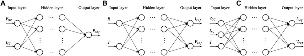
FIGURE 3. The neural network of ANN-based MPPT. (A) The method based on electrical data; (B) The method based on non-electrical data; (C) The method based on mixed data.
The widely used MPPT control methods based on artificial intelligence algorithms include GA-based MPPT control methods and PSO-based control methods. Fixed sampling time strategy (FSTS) (Kakosimos and Kladas, 2011) and variable sampling time strategy (VSTS) (Khalessi et al., 2020) are used to test the performance of each individual. And the results are used as a reference for population iteration. After that, the individuals in the population combine as parents to produce children, which is expressed as:
where i, j are random integers from 1 to the population size. In this process, a mutation will occur with a very small probability. The random-effects on child individuals are expressed as:
where
where
PSO is a simple, high-speed optimization algorithm. The velocity of the particle in the search space is v, and its location x represents the voltage value of RES. The particles get a locally optimal solution at the optimal position
where w is the inertia weight, c1 and c2 are the acceleration coefficients; r1, r2 are the random numbers between 0 and 1.
The
Active Load Sharing
The active load sharing is the current distribution control with a communication channel among converters. It can be classified as the master-slave control and the average current load sharing.
The Master-Slave control refers to control the slave controllers of each module using a master controller in real-time (Javaid et al., 2017a). The master controller executes the voltage control method. And the slave controller executes the current control method. The objective of the master-slave control is to realize a real-time unification of the current signals. The effective voltage reference signal of the slave module needs to be adjusted according to the voltage of the master module to make its output current equal to the output current of the master module (Burmester et al., 2018). The structure of Master-Slave control is shown in Figure 4.
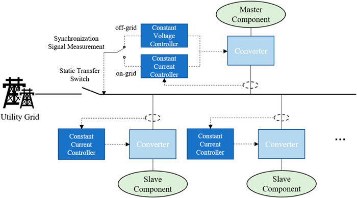
FIGURE 4. Structure of the Master-slave control.
The DCNG under the Master-Slave control changes the control methods of different controllers in time to achieve the master-slave command relationship. When the DCNG operates in grid-connected mode, the utility grid assumes the stability of voltage. All RESs in the DCNG will run in the current control mode, including the master component. In this way, the DCNG can obtain constant active power from the public grid. The slave component will operate according to the reference current provided by the master component. When the utility grid fails, DCNG turns into island operation mode by opening the static transfer switch. At this time, the master component will operate in the constant voltage control mode and assume the stability of voltage.
The Master-Slave control can be divided into the Master-Slave control with dedicated master modules and automatic Master-Slave control. As the name implies, a master-slave control with a dedicated master module will select a fixed module as the master module. Master-Slave control has the advantages of simple principle, high voltage stability, accurate control. But it requires reliable communication (Javaid et al., 2017b). Automatic Master-Slave control is also called voltage margin control. Voltage margin control is an extension of the master-slave control (Liu et al., 2018). It is equivalent to an improved DC voltage control with multiple optional power balance nodes. The module with the largest output current temporarily operates as the master module. And other modules will adjust the output current according to the current reference provided by it. When a master module fails or its voltage reaches the limit, another module with maximum power output will replace it. In this way, the reliability and flexibility of DCNG are improved.
In the average current sharing, the average current of all converters is calculated by the average load controller to provide a reference for each converter (Nawaz et al., 2020). The control technology diagram is shown in Figure 5. Each converter is equipped with a controller including an inner loop and an outer loop to match the average current.
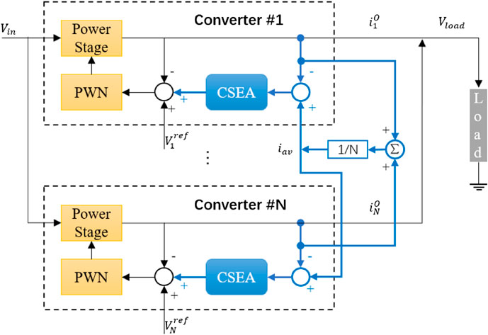
FIGURE 5. The control technology diagram of average load sharing.
The average current of all inverters is calculated by the average load controller to provide a reference for each inverter. The control technology diagram is shown in Figure 5. Each converter is equipped with a controller including an inner loop current loop and an outer loop voltage loop to match the average current. The average current is connected to the current loop as a feedback signal. The error between the output current of the converter and the average current is connected to the voltage loop through a Current Sharing Error Amplifier (CSEA) and an incremental
Passive Load Sharing
The droop controller installed on the top of the inner loop is used to adjust the output voltage reference of the internal voltage loop. The principle of droop control is to adjust the state of each unit to make it operates according to the droop characteristics. The droop characteristics are shown in Figure 6. and represented by Eqs 13Eqs 14, Nasir et al. (2018).
where
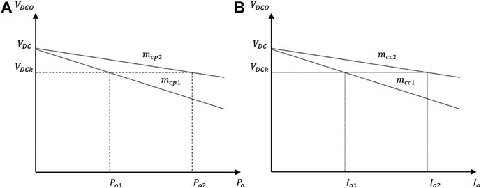
FIGURE 6. Droop characteristic curve. (A) Power droops (B) current droops.
There are also many improved methods for droop control, such as adaptive droop control, mode adaptive droop control, virtual resistance-based droop control and intelligent techniques-based droop control.
Different from conventional droop control, the droop coefficient of adaptive droop control is not fixed, but the function of the real-time output power or voltage level of the converters. This can prevent the voltage or power from exceeding the limit in the process of redistributing the load. Generally, the droop coefficient is adjusted by the adaptive PI controller to eliminate the current sharing error in each component like (Chaudhuri and Chaudhuri, 2013):
where
The principle of the virtual impedance-based droop control is to introduce virtual impedance on the output side of the converter to simulate the line impedance and change the output characteristics (Dogga et al., 2015). The virtual impedance can be considered in the feedback loop. By adjusting the size of the virtual impedance
where
In the mode-adaptive droop control mode, one of the three bus regulation unit that the utility grid, the ESSs and DEGs operate in droop control mode to maintain the power balance of DCNG. The other two units operate under a constant power control mode. The different droop characteristics with different bus regulating unit are shown in Figure 7.
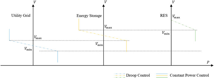
FIGURE 7. Droop characteristics with different bus regulating unit.
When the output voltage of the bus regulation unit exceeds the limit, another unit replaces it. The switching order from low to high according to the voltage limit is the utility grid, energy storage devices, and distributed power generators. The droop control can also be combined with other control modes, such as the MPPT described above. This control method has higher freedom than the conventional droop control method and does not require an additional control center and communication lines. It achieves a fully adaptive adjustment of the converter and provides higher reliability and flexibility for the system.
Since the distribution characteristics of conventional droop control are affected by load mutations and other uncertain factors (Lu et al., 2020a), it is difficult to guarantee accurate power distribution. Fuzzy droop control combines the characteristics of the fuzzy algorithm and the droop control. It correlates the droop coefficient with energy storage device output power, DC bus voltage, and other parameters dynamically adjust the droop coefficient, optimizes the droop curve in real-time, and achieves the purpose of proper power distribution (Farzaneh et al., 2020). However, in the DCNG, the line impedance has a great influence on the voltage. Only when the line impedance of each module is small, fuzzy droop control can realize the average current sharing (Mosayebi et al., 2020c).
The linear droop control strategy is simple to implement. Generally speaking, the higher the droop coefficient, the better the current sharing accuracy. However, due to the influence of line impedance and different converters, linear droop control cannot guarantee accurate current sharing and voltage deviation. Therefore, droop control is often a compromise between output voltage regulation and current sharing between converters (Mosayebi et al., 2020c). The non-linear droop characteristic refers to a small droop coefficient under light load and a high droop coefficient under heavy load i.e., it values the accuracy of load sharing under heavy load or the performance of voltage regulation under a light load (Meng et al., 2015). The corresponding equation for calculating the reference voltage is:
where
Figure 8. illustrates the improvement in current sharing with non-linear droop control when there is a small error in the nominal voltage for two RESs. The difference between the currents of the two power supplies is (
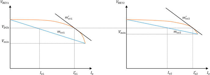
FIGURE 8. Performance comparison of the linear droop control and the non-linear droop control.
This article summarizes the advantages and disadvantages of the local control techniques in Table 2.
TABLE 2. Comparison of local control techniques.
Coordinated Control
Coordinated control is the global control of DCNG. It can be implemented in a centralized manner with a central controller or a distributed manner with a sparse communication network. Therefore, the method of coordinated control is reflected in the control structure. In this Section, the control structure is divided into centralized control, decentralized control, distributed control, and hybrid control. The characteristics and newest techniques of them are discussed.
Centralized Control
Under the centralized control mode, the entire DCNG is controlled by a centralized controller. Figure 9A shows the topology of the centralized control. The solid lines in the figure are power transmission lines, and the dashed lines are communication lines. Firstly, the related data are measured by measuring devices such as a smart meter. The measurement signal is transmitted through the communication lines to the centralized controller for analysis and calculation. Then the centralized controller sends the control signal to control the decentralized modules directly. The centralized control mode is the simplest to implement among all control modes, but it requires a reliable communication system. The influence of hybrid electric vehicles was analyzed in Pahasa and Ngamroo (2018), and a centralized model predictive control method. This method takes into account the change in the number of hybrid electric vehicles was proposed in it, which can suppress the frequency fluctuation of the system and optimize the residual power of PV.
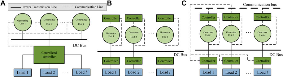
FIGURE 9. Three schematic diagram of coordinated control.
Decentralized Control
The decentralized control mode is no need a centralized controller, but each control unit has a decentralized controller that controls its region (Schonberger et al., 2006; Hirase et al., 2018; Ciavarella et al., 2020; Nasir et al., 2019). Each controller is independent and no communication bus is required. Figure 9B shows the topology of the decentralized control. The decentralized control mode does not depend on the communication system, so it does not need to consider communication failure and other problems. A self-sustaining and flexible control strategy for hierarchical autonomous DCNG based on decentralized control was constructed in Nasir et al. (2019). The local control manages the power balance. The coordinated control is responsible for eliminating the voltage deviation of DC bus. In the proposed control strategy, the battery charging state and the external DC bus signal is considered to avoid the battery overcharge/deep discharge and the external DC bus crash.
However, the single point of failure of the physical system is likely to expand the scope of failure due to untimely communication, which will affect the security of the system. The most common decentralized control methods are DC bus signal (DBS), power line signal (PLS) and the droop control described above. The DBS and PLS will be described in detail below.
DBS is the most basic decentralized control method, which uses the DC bus as a transmission channel for digital signals (Schonberger et al., 2006). Relying on the DBS, the coordinated and static operation of different energy sources can be realized by improved static V-I voltage drop characteristics. The control strategy of DBS depends on the measured value of the local voltage of the DC bus. Figure 10. shows the three modes of DBS control strategy, including utility grid dominating, storage dominating and RES dominating, and the relationship between the selections of the three modes and the DC bus voltage.
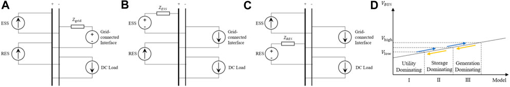
FIGURE 10. Different operation mode in DBS. (A) Utility dominating, (B) Storage dominating, (C) RES dominating, (D) Operation mode selection depending on DC bus voltage.
In Figure 10 the dominating unit is demonstrated by the Thevenin circuit. The value of the voltage source is equal to the voltage reference, and the size of the series impedance is equal to the virtual impedance. Other units are represented by a current source. DBS only relies on local information and does not require any other components except the interface converter (Ciavarella et al., 2020). Therefore, this is an easy-to-implement decentralized control method. The main concern is to select the appropriate voltage level needed to identify the different operating modes (Nasir et al., 2019). The too-large difference between adjacent levels will cause the DC bus voltage fluctuation to exceed the acceptable range. If the difference between the voltage levels is too small, the sensor cannot accurately identify the operating mode.
PLS is another decentralized control method. The principle of PLS is to inject a sinusoidal signal with a specific frequency into the DC bus after amplification by an amplifier. Then the controller sends or receives information about the status, performance, and working model of the device to the converter (Nguyen et al., 2020). Noted that, although PLS relies on data communication, it does not require an additional communication system. Therefore, PLS is considered as a decentralized control structure (Hirase et al., 2018). And unlike DBS, the signal transmitted by PLS in the DC bus is additionally injected instead of the electrical characteristic signal sent by the DC bus itself. Sinusoidal signals are generally injected into the DC bus at a fixed time interval, so they are mostly used to change the working mode of equipment or isolate damaged components in the system and are not suitable for power-sharing. PLS improve extent voltage quality compared with DBS and droop control.
Distributed Control
Distributed control mode combines the characteristics of centralized control and decentralized control mode. There are only decentralized controllers and no central controller, but each controller can realize information exchange (Xia et al., 2018). Figure 9C shows the topology of the distributed control. The distributed control system is more secure than the decentralized control and less dependent on the communication system than the centralized control system. Haroun, R. and Yoomak, S. applied the power flow coloring theory to the energy management strategy, introduced the master-slave control scheme. The feedback control based on the time slot is integrated. And a cooperative distributed control method is proposed, which can buffer the power fluctuation and maintain the voltage stability (Haroun et al., 2020; Yoomak and Ngaopitakkul, 2020).
In the DCNG under distributed control mode, the information exchange can be only through digital communication lines. If there is no digital communication line between two decentralized controllers, they cannot directly access each other data. Therefore, how to avoid control deviation and ensure the reliability of the local controller through limited information is the key to the distributed control strategy (Lucía et al., 2013b).
The converter under consensus control gets interest variables from the adjacent controller to find a local control protocol that drives all nodes to have the same constant steady-state (Rafiee and Sirouspour, 2018). The exchanging variables can be module voltage, current, or state of charge if energy storage is integrated. All the algebraic differences of these variables will be added to the generator. In this way, the decentralized controllers will adjust the connected unit according to the state of the decentralized controllers adjacent. Another option is to use a non-zero input offset in one of the local controllers (Samet et al., 2019). In both cases, the latter has wide applicability.
Each unit operates in a multi-agent control mode is composed of a device layer, the main controller layer and an agent layer. The equipment layer at the bottom is used to connect the physical electrical equipment and the platform. The main controller that controls the power output of electrical equipment is located in the middle layer. Droop control is usually applied in this layer. The top agent and communication layer provides coordinated control. The agent layer is the main element of a multi-agent system. It can be a physical or virtual entity located in the environment. The agent needs to react autonomously to the environment and communicate with other agents. The implementation method uses a distributed control circuit with a consistent algorithm to obtain information between neighboring agent units, and iteratively evaluates the global average value to provide the lower controller with a control correction. However, when the number of agents is too large, it is difficult to achieve global consistency. An effective solution is event-triggered control, which is a communication method that does not require continuous information exchange between units. A unified active power distribution method based on distributed dynamic event trigger control is developed in Wang et al. (2020a). The event-triggered mechanism based on dynamic samples reduces the communication between units. The gain and event-triggered parameters of the controller are set by the maximum and second eigenvalues of the Laplacian matrix.
Hybrid Control
Hybrid control can be divided into hybrid centralized control and hybrid distributed control. Hybrid centralized control is a mixture of centralized control and decentralized control. There are both centralized and decentralized controllers. The central controller is used to centralize various information collected by the decentralized controllers, then send the commands to the decentralized controllers. The decentralized controller adjusts its respective area. Hybrid distributed control is generally applied to small DCNG. If the number of DCNGs is large, then hybrid centralized control, also called hierarchical control, is limited. Hierarchical control is to divide levels based on centralized control, and each level sets up the affiliation between controllers to form a radial control network. Hierarchical control makes different control levels independent, so the system can operate normally even the centralized controller fails. It can still ensure the normal operation of the system with higher reliability. Hierarchical control also has a wide range of applications in DCNG. For example, a two-stage hierarchical energy management system for smart homes was proposed in Luo et al. (2019). On the one hand, the authors use the staged-optimization method to overcome the uncertainty and randomness from the demand side. On the other hand, the actual operation model is established by the hierarchical control method. An effective power management program based on the hierarchical control strategy in smart DCNG was established in Latifi et al. (2020) to build an energy trading mechanism to avoid the impact of grid uncertainty and local transactions. Both of these two control methods can improve the reliability of the system. The latter has a stronger control ability but a higher dependence on communication lines. Table 3 shows the comparisons of different coordinated control strategies.
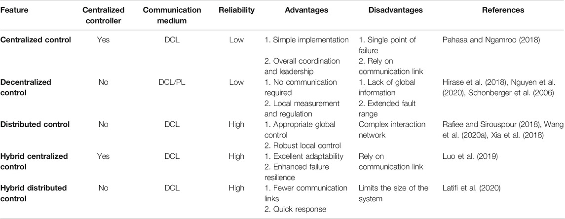
TABLE 3. Comparisons of coordinated control strategies.
Discussion of the Future Direction
Combined with the review of DCNG control strategies in this paper, the direction of further research is discussed as follows:
1) The grid connection of large-scale DCNGs will lead to a reactive power shortage in load centers and impairs the system's ability to withstand unexpected events. Some RESs in DCNG need to absorb reactive power from the system when outputting active power, and a large amount of reactive power is also needed to compensate for nodal voltages when the system is at fault. If the RESs fail to receive sufficient reactive power, it will further worsen the system contingency. One solution is to use an AC/DC hybrid nano-grid, which can integrate reactive power compensators to supplement the shortage of reactive power. The design and implementation of an AC/DCNG based on field experiment scenarios are introduced in (Tudu et al., 2019). And the corresponding simulation model carried out on HOMER software was developed by the National Renewable Energy Laboratory (NREL), USA. Another method is to introduce the virtual inertia control to provide inertia and damping support for the RESs (Debnath et al., 2021; Terazono et al., 2021).
2) RESs have problems such as low efficiency of energy utilization and high curtailment of energy. The integrated energy system can break the barriers among different energy sources and make complementary utilization of multiple types of energy. In the context of the deep coupling of electricity, heat, natural gas and other energy sources, DCNG should consider the impact of comprehensive energy loads (An et al., 2020), while complex physical properties of various energy sources and interacted energy flow in different time scales should also be considered.
3) Future DCNG will integrate high-penetration renewable energy, energy storage devices, and flexible loads. Traditional offline day-ahead scheduling is difficult to meet the optimal scheduling objective, and real-time energy management is required to provide safe and reliable power services. Consequently, A fast and reliable communication system is a basis, and Cyber Physics System (CPS) integrates environment perception, embedded computing, and network communication to form a multi-dimensional heterogeneous complex system integrating real-time perception, dynamic control and information services (Wang et al., 2020b).
Another requirement is an efficient algorithm that can coordinate a large number of DCNGs (An et al., 2020). Since AlphaGo defeated human Go masters, AI algorithms have received extensive attention in various fields. In the real-time scheduling of DCNG clusters, deep reinforcement learning (DRL) algorithms can provide new ideas for handling complex DCNG control problems through autonomous learning (Qazi et al., 2020). Real-time energy management also requires high-speed solutions. It is necessary to study the corresponding parallel computing technology to improve the calculation speed and maintain the independence of DCNG (Xia et al., 2019b).
4) The short-term and continuous interference characteristics of utility grids, power sources, and loads will cause DCNG steady-state or transient power quality problems, such as DC voltage fluctuations caused by continuous changes of the active power for RESs or loads, voltage deviations caused by unbalanced active power, and harmonics caused by a large number of power electronic devices implemented (Liu et al., 2021). Moreover, the load was strictly controlled by the converter, and its dynamics are described by a constant power model. However, with the introduction of flexible loads and the demand for alleviating reactive power shortages, more complex and flexible dynamic load models should be considered. Therefore, it is essential to study the harmonic characteristics of converters and the dynamic characteristics of loads, and analysis of possible power quality problems and quantified indicators, and control strategies are the key directions in the future (Shu et al., 2021). A new oscillatory component load model was derived from a second-order differential equation in (Paidi et al., 2020), which consisted of static, exponential recovery, and damped oscillatory components and was used in real-time parameter estimation of the dynamic load model.
5) Though the research on power systems uncertainty is a hot topic, related techniques are not mature for DCNG where a bottom-up structure is close to the demand side with RES. All uncertainty caused by the fluctuations of load and RESs should be considered carefully in control strategies. At present, FL-based control strategies are commonly used to deal with the uncertain input of local controllers, but far from handling the uncertainty of the coordinated control. Therefore, energy management strategies that consider uncertainty is also an urgent issue to be solved (Xia et al., 2016; Lu et al., 2019; Latifi et al., 2020; Lu et al., 2020b).
Conclusion
DCNG provides new solutions for the construction of smart grids and green buildings in the future. Its personalized and modular characteristics make it an ideal choice for a bottom-up power system structure. This article summarizes the structure and control methods of DCNG, and draws the following conclusions.
DCNG adopts a hierarchical control scheme similar to microgrids. The control strategy can be divided into local control and coordinated control. The local control realizes the voltage, current control, and primary power-sharing of the units. Droop control has been widely used in local control due to its precise current sharing and excellent voltage regulation abilities. Moreover, the improved droop control overcomes the shortcomings of the traditional droop control and exhibits excellent voltage regulation and current sharing abilities regardless of light or heavy loads. Coordinated control further improves the accuracy of power-sharing and power quality of the grid systems. According to whether a centralized controller is used and whether it depends on communication lines, coordinated control is further divided into centralized control, decentralized control, and distributed control. Some studies have mixed multiple control structures. The distributed control scheme and corresponding communication technologies should be further studied with the multi-agent-based AI algorithms such that these control strategies can operate DCNG stably in all operation modes.
Author Contributions
HF: Conceptualization, Methodology, Investigation, Validation; WY: Writing-Original draft preparation, Methodology, Investigation, Software, Validation. SX: Writing-Review & Editing, Methodology, Software, Validation, Project administration.
Funding
This work was supported partially by the National Natural Science Foundation of China (52077075), the Jiangsu Basic Research Project (BK20180284), and the Fundamental Research Funds for the Central Universities (2019MS007). The authors would also thank the editor and reviewer for their valuable comments.
Conflict of Interest
The authors declare that the research was conducted in the absence of any commercial or financial relationships that could be construed as a potential conflict of interest.
References
Adda, R., Ray, O., Mishra, S. K., and Joshi, A. (2013). Synchronous-reference-frame-based control of switched boost inverter for standalone DC nanogrid applications. IEEE Trans. Power Electron. 28, 1219–1233. doi:10.1109/TPEL.2012.2211039
Al-Majidi, S. D., Abbod, M. F., and Al-Raweshidy, H. S. (2020). A particle swarm optimisation-trained feedforward neural network for predicting the maximum power point of a photovoltaic array. Eng. Appl. Artif. Intell. 92, 103688. doi:10.1016/j.engappai.2020.103688
An, S., Wang, H., and Yuan, X. (2020). Real-time optimal operation control of micro energy grid coupling with electricity- thermal -gas considering prosumer characteristics. IEEE Access 8. 216566–216579. doi:10.1109/ACCESS.2020.3041709
Azab, M. (2017). “PV power harvesting scheme for nanogrid applications using meteorological data,” in 2017 IEEE international conference on environment and electrical engineering and 2017 IEEE industrial and commercial power systems Europe (EEEIC/I&CPS Europe) (Milan: Institute of Electrical and Electronics Engineers (IEEE)), 1–6.
Azimi, S. M., and Lotfifard, S. (2021). A nonlinear controller design for power conversion units in islanded Micro-grids using interconnection and damping assignment tracking control. IEEE Trans. Sustain. Energy 12, 284–292. doi:10.1109/TSTE.2020.2992535
Bagewadi, M. D., Chobe, C. R., Jagtap, P. S., Siddiquee, M., and Dambhare, S. S. (2020). Buck-boost derived interleaved hybrid converter for residential nanogrid applications. IET Power Electronic. 13, 377–388. doi:10.1049/iet-pel.2019.0521
Bampoulas, A., and Karlis, A. (2020). Real‐time energy storage management system of a nanogrid integrating photovoltaics and V2G operation. J. Eng. 2020, 32–40. doi:10.1049/joe.2018.5247
Bin Mohamad Saifuddin, M. R., Logenthiran, T., Naayagi, R. T., and Woo, W. L. (2019). A nano-biased energy management using reinforced learning multi-agent on layered coalition model: consumer sovereignty. IEEE Access 7, 52542–52564. doi:10.1109/ACCESS.2019.2911543
Burmester, D., Rayudu, R., and Seah, W. K. G. (2018). Use of maximum power point tracking signal for instantaneous management of thermostatically controlled loads in a DC nanogrid. IEEE Trans. Smart Grid 9, 6140–6148. doi:10.1109/TSG.2017.2704116
Chang, Y.-C., Chang, H.-C., and Huang, C.-Y., (2018). Design and implementation of the battery energy storage system in DC Micro-grid systems. Energies. 11, 1566. doi:10.3390/en11061566
Chaudhuri, N. R., and Chaudhuri, B. (2013). Adaptive droop control for effective power sharing in multi-terminal DC (MTDC) grids. IEEE Trans. Power Syst. 28, 21–29. doi:10.1109/TPWRS.2012.2203390
Cho, C., Jeon, J.-H., Kim, J.-Y., Kwon, S., Park, K., and Kim, S. (2011). Active synchronizing control of a microgrid. IEEE Trans. Power Electron. 26, 3707–3719. doi:10.1109/TPEL.2011.2162532
Ciavarella, R., Graditi, G., Valenti, M., Pinnarelli, A., Barone, G., and Vizza, M. (2020). “An advanced DBS strategy for a DC nanogrid integrating several energy storage technologies,” in 2020 international symposium on power electronics, electrical drives, automation and motion (SPEEDAM) (Sorrento, Italy: Institute of Electrical and Electronics Engineers (IEEE)), 351–356.
Daniel, B., Ramesh, R., Winston, S., and Daniel, A. (2017). A review of nanogrid topologies and technologies. Renew. Sustainable Energy Rev. 67, 760–775. doi:10.1016/j.rser.2016.09.073
Debnath, S., Marthi, P., Xia, Q., Pan, J., Saeedifard, M., Vipin, V. N., et al. (2020). Renewable integration in hybrid ac-dc systems using multi-port autonomous reconfigurable solar power plant (MARS). IEEE Trans. Power Syst. 36, 1. doi:10.1109/TPWRS.2020.3037520
Dogga, S., Surendar, V., Ponnambalam, P., and Praveen Kumar, M. (2015). “Boost derived hybrid converter implementation using fuzzy controller,” in 2015 international conference on technological advancements in power and energy (TAP Energy) (Kollam, India: Institute of Electrical and Electronics Engineers (IEEE)), 381–386.
Dursun, M., and Gorgun, A. (2017). “Analysis and performance comparison of DC-DC power converters used in photovoltaic systems,” in 2017 4th international conference on electrical and electronic engineering (ICEEE) (Ankara: Institute of Electrical and Electronics Engineers (IEEE)), 113–119.
Elsayad, N., Moradisizkoohi, H., and Mohammed, O. A. (2019). Design and implementation of a new transformerless bidirectional DC-DC converter with wide conversion ratios. IEEE Trans. Ind. Electron. 66, 7067–7077. doi:10.1109/TIE.2018.2878126
Fairley, P. (2012). DC versus AC: the second war of currents has already begun [In My View]. IEEE Power Energy Mag. 10, 104–103. doi:10.1109/MPE.2012.2212617
Farzaneh, H., Shokri, M., Kebriaei, H., and Aminifar, F. (2020). Robust energy management of residential nanogrids via decentralized mean field control. IEEE Trans. Sustain. Energy 11, 1995–2002. doi:10.1109/TSTE.2019.2949016
Francés, A., Asensi, R., García, O., Prieto, R., and Uceda, J. (2018). Modeling electronic power converters in smart DC microgrids-an overview. IEEE Trans. Smart Grid 9, 6274–6287. doi:10.1109/TSG.2017.2707345
Franco-Mejia, E., Plazas-Rosas, R. A., Gil-Caicedo, A., Franco-Manrique, R., and Gomez-Luna, E. (2017). “Pilot nanogrid at universidad del valle, for research and training in control and management of electrical networks in non-interconnected areas,” in Non-interconnected areas 2017 IEEE 3rd Colombian conference on automatic control (CCAC) (Cartagena: Institute of Electrical and Electronics Engineers (IEEE)), 1–6.
Ganesan, S. I., Pattabiraman, D., Govindarajan, R. K., Rajan, M., and Nagamani, C. (2015). Control scheme for a bidirectional converter in a self-sustaining low-voltage DC nanogrid. IEEE Trans. Ind. Electron. 62, 6317–6326. doi:10.1109/TIE.2015.2424192
Goud, P. C. D., and Gupta, R. (2020). Solar PV based nanogrid integrated with battery energy storage to supply hybrid residential loads using single‐stage hybrid converter. IET Energy Syst. Integr. 2, 161–169. doi:10.1049/iet-esi.2019.0030
Guerrero, J. M., Vasquez, J. C., Matas, J., de Vicuna, L. G., and Castilla, M. (2011). Hierarchical control of droop-controlled AC and DC microgrids-A general approach toward standardization. IEEE Trans. Ind. Electron. 58, 158–172. doi:10.1109/TIE.2010.2066534
Hadji, S., Gaubert, J.-P., and Krim, F. (2018). Real-time genetic algorithms-based MPPT: study and comparison (Theoretical an Experimental) with conventional methods. Energies 11, 459. doi:10.3390/en11020459
Haroun, R., El Aroudi, A., Cid-Pastor, A., Vidal-Idiarte, E., Valderrama-Blavi, H., and Martinez-Salamero, L. (2020). Modelling and control of modular DC-nanogrids based on loss-free resistors. IEEE Access 8, 33305–33317. doi:10.1109/TPEL.2018.2828538
Hirase, Y., Noro, O., Nakagawa, H., Yoshimura, E., Katsura, S., Abe, K., et al. (2018). Decentralised and interlink-less power interchange among residences in microgrids using virtual synchronous generator control. Appl. Energy 228, 2437–2447. doi:10.1016/j.apenergy.2018.07.103
Javaid, S., Kato, T., and Matsuyama, T. (2017a). Power flow coloring system over a nanogrid with fluctuating power sources and loads. IEEE Trans. Ind. Inf. 13, 3174–3184. doi:10.1109/TII.2017.2733550
Javaid, S., Kurose, Y., Kato, T., and Matsuyama, T. (2017b). Cooperative distributed control implementation of the power flow coloring over a nano-grid with fluctuating power loads. IEEE Trans. Smart Grid 8, 342–352. doi:10.1109/TSG.2015.2509002
Kakosimos, P. E., and Kladas, A. G. (2011). Implementation of photovoltaic array MPPT through fixed step predictive control technique. Renew. Energy 36, 2508–2514. doi:10.1016/j.renene.2011.02.021
Khalessi, N., Niroomand, M., Dadkhah, J., and Nikouei, S. Y. (2020). A firework-based GMPPT with variable sampling time for PV systems. Math. Probl. Eng. 2020, 6130202. doi:10.1155/2020/6130202
Kleftakis, V., Lagos, D., Papadimitriou, C., and Hatziargyriou, N. D. (2019). Seamless transition between interconnected and islanded operation of DC Microgrids, IEEE Trans. Smart Grid 10, 248–256. doi:10.1109/TSG.2017.2737595
Latifi, M., Rastegarnia, A., Khalili, A., Bazzi, W. M., and Sanei, S. (2020). A self-governed online energy management and trading for smart micro/nano-grids. IEEE Trans. Ind. Electron. 67, 7484–7498. doi:10.1109/TIE.2019.2945280
Li, H., Ren, F., Liu, C., Guo, Z., Lu, J., Zhang, B., et al. (2020). An extended stability analysis method for paralleled DC-DC converters system with considering the periodic disturbance based on floquet theory. IEEE Access 8, 9023–9036. doi:10.1109/ACCESS.2019.2960535
Li, Z., Xu, Y., Feng, X., and Wu, Q. (2021). Optimal stochastic deployment of heterogeneous energy storage in a residential multienergy microgrid with demand-side management. IEEE Trans. Ind. Inf. 17, 991–1004. doi:10.1109/TII.2020.2971227
Liu, F., Ruan, X., Huang, X., and Qiu, Y. (2021). Second harmonic current reduction for two-stage inverter with DCX-LLC resonant converter in front-end DC-DC converter: modeling and control. IEEE Trans. Power Electron. 36, 4597–4609. doi:10.1109/TPEL.2020.3025924
Liu, G., Caldognetto, T., Mattavelli, P., Magnone, P., Mattavelli, P., and Magnone, P. 2019). Power-based droop control in DC microgrids enabling seamless disconnection from upstream grids. IEEE Trans. Power Electron. 34, 2039–2051. doi:10.1109/TPEL.2018.2839667
Liu, G., Khodamoradi, A., Mattavelli, P., Caldognetto, T., and Magnone, P. (2018). “Plug and play DC-DC converters for smart DC nanogrids with advanced control ancillary services,” in 2018 IEEE 23rd international workshop on computer aided modeling and design of communication links and networks (CAMAD) (Barcelona: Institute of Electrical and Electronics Engineers (IEEE)), 1–6.
Lu, X., Chan, K. W., Xia, S., Shahidehpour, M., and Ng, W. H. (2020a). An operation model for distribution companies using the flexibility of electric vehicle aggregators. IEEE Trans. Smart Grid 1, doi:10.1109/TSG.2020.3037053
Lu, X., Chan, K. W., Xia, S., Zhang, X., Wang, G., and Li, F. (2020b). A model to mitigate forecast uncertainties in distribution systems using the temporal flexibility of EVAs. IEEE Trans. Power Syst. 35, 2212–2221. doi:10.1109/TPWRS.2019.2951108
Lu, X., Chan, K. W., Xia, S., Zhou, B., and Luo, X. (2019). Security-constrained multiperiod economic dispatch with renewable energy utilizing distributionally robust optimization. IEEE Trans. Sustain. Energy 10, 768–779. doi:10.1109/TSTE.2018.2847419
Lucía, O., Cvetkovic, I., Sarnago, H., Boroyevich, D., Mattavelli, P., and Lee, F. C. (2013a). Design of home appliances for a DC-based nanogrid system: an induction range study case. IEEE J. Emerg. Sel. Top. Power Electron. 1, 315–326. doi:10.1109/JESTPE.2013.2283224
Lucia, O., Cvetkovic, I., Boroyevich, D., Mattavelli, P., and Lee, F. C. (2013b). “Design of household appliances for a DC-based nanogrid system: an induction heating cooktop study case,” in 2013 Twenty-Eighth annual IEEE applied power electronics conference and exposition (Long Beach, CA: Institute of Electrical and Electronics Engineers (IEEE)), 1576–1583.
Luo, F., Ranzi, G., Wang, S., and Dong, Z. Y. (2019). Hierarchical energy management system for home microgrids. IEEE Trans. Smart Grid 10, 5536–5546. doi:10.1109/TSG.2018.2884323
Maroufi, O., Choucha, A., and Chaib, L. (2020). Hybrid fractional fuzzy PID design for MPPT-pitch control of wind turbine-based bat algorithm. Electr. Eng. 102, 2149–2160. doi:10.1007/s00202-020-01007-5
Martin, K., Vazquez, A., Arias, M., and Sebastian, J. (2018). “Optimization procedure of source/sink converters for DC power distribution nano-grids,” in 2018 IEEE 19th workshop on control and modeling for power electronics (Compel) (Padua: Institute of Electrical and Electronics Engineers (IEEE)).
Martin-Martínez, F., Sánchez-Miralles, A., and Rivier, M. (2016). A literature review of microgrids: a functional layer based classification. Renew. Sustainable Energy Rev. 62, 1133–1153. doi:10.1016/j.rser.2016.05.025
Meng, L., Dragicevic, T., Vasquez, J. C., and Guerrero, J. M. (2015). Tertiary and secondary control levels for efficiency optimization and system damping in droop controlled DC-DC converters. IEEE Trans. Smart Grid 6, 2615–2626. doi:10.1109/TSG.2015.2435055
Merchaoui, M., Hamouda, M., Sakly, A., and Mimouni, M. F. (2020). Fuzzy logic adaptive particle swarm optimisation based MPPT controller for photovoltaic systems. IET Renew. Power Gener. 14, 2933–2945. doi:10.1049/iet-rpg.2019.1207
Mosayebi, M., Gheisarnejad, M., and Khooban, M.-H. (2020a). An intelligent type-2 fuzzy stabilization of multi-DC nano power grids. IEEE Trans. Emerg. Top. Comput. Intell. 1–6. doi:10.1109/TETCI.2020.2977676
Mosayebi, M., Sadeghzadeh, S. M., Guerrero, J. M., and Khooban, M.-H. (2020b). Stabilization of DC nanoGrids based on non-integer general type-II fuzzy system. IEEE Trans. Circuits Syst., 67, 3108. doi:10.1109/TCSII.2020.2964719
Mosayebi, M., Sadeghzadeh, S. M., Khooban, M. H., and Guerrero, J. M. (2020c). Decentralised non‐linear I-V droop control to improve current sharing and voltage restoration in DCNG clusters. IET Power Electron. 13, 248–255. doi:10.1049/iet-pel.2019.0263
Murdianto, F. D., Efendi, M. Z., Widarsono, K., and Azizi, M. (2018). “Robustness analysis of PID controller bidirectional SEPIC/Zeta for energy management in DC nanogrid isolated system,” in 2018 3rd international conference on information technology, information system and electrical engineering (Yogyakarta, Indonesia: ICITISEE), 406–411.
Nag, S. S., Adda, R., Ray, O., and Mishra, S. K. (2013). “Current-fed switched inverter based hybrid topology for DC nanogrid application,” in IECON 2013-39th annual conference of the IEEE industrial electronics society (Vienna: Institute of Electrical and Electronics Engineers (IEEE)), 7146–7151.
Nasir, M., Jin, Z., Khan, H. A., Zaffar, N. A., Vasquez, J. C., and Guerrero, J. M. (2019). A decentralized control architecture applied to DC nanogrid clusters for rural electrification in developing regions. IEEE Trans. Power Electron. 34, 1773–1785. doi:10.1109/TPEL.2018.2828538
Nasir, M., Khan, H. A., Hussain, A., Mateen, L., and Zaffar, N. A. (2018). Solar PV-based scalable DC microgrid for rural electrification in developing regions. IEEE Trans. Sustain. Energy 9, 390–399. doi:10.1109/TSTE.2017.2736160
Navarro-Rodríguez, A., García, P., Georgious, R., and García, J. (2019). Adaptive active power sharing techniques for DC and AC voltage control in a hybrid DC/AC microgrid. IEEE Trans. Ind. Applicat. 55, 1106–1116. doi:10.1109/TIA.2018.2873543
Nawaz, A., Wu, J., and Long, C. (2020). Mitigation of circulating currents for proportional current sharing and voltage stability of isolated DC microgrid. Electric Power Syst. Res. 180, 106123. doi:10.1016/j.epsr.2019.106123
Nguyen, T. L., Guerrero, J. M., and Griepentrog, G. (2020). A self-sustained and flexible control strategy for islanded DC nanogrids without communication links. IEEE J. Emerg. Sel. Top. Power Electron. 8, 877–892. doi:10.1109/JESTPE.2019.2894564
Ochs, D. S., Mirafzal, B., and Sotoodeh, P. (2014). A method of seamless transitions between grid-tied and stand-alone modes of operation for utility-interactive three-phase inverters. IEEE Trans. Ind. Applicat. 50, 1934–1941. doi:10.1109/TIA.2013.2282761
Pahasa, J., and Ngamroo, I. (2018). Coordinated PHEV, PV, and ESS for microgrid frequency regulation using centralized model predictive control considering variation of PHEV number. IEEE Access 6, 69151–69161. doi:10.1109/ACCESS.2018.2879982
Paidi, E. S. N. R., Nechifor, A., Albu, M. M., Yu, J., and Terzija, V. (2020). Development and validation of a new oscillatory component load model for real-time estimation of dynamic load model parameters. IEEE Trans. Power Delivery 35, 618–629. doi:10.1109/TPWRD.2019.2918059
Patterson, B. T. (2012). DC, come home: DC microgrids and the birth of the “Enernet” IEEE Power Energy Mag. 10, 60–69. doi:10.1109/MPE.2012.2212610
Qazi, H. S., Liu, N., Wang, T., Masood, A., and Sattar, B. (2020). “A tri-generation system based Micro-grid energy management: a deep reinforcement learning approach,” in 2020 international conference on electrical engineering and control technologies (Melbourne:CEECT).
Rafiee, S. M., and Sirouspour, S. (2018). Energy management in a network of grid-connected microgrids/nanogrids using compromise programming. IEEE Trans. Smart Grid 3, 2180–2191. doi:10.1109/TSG.2016.2608281
Rocha, H. R. O., Honorato, I. H., Fiorotti, R., Celeste, W. C., Silvestre, L. J., and Silva, J. A. L. (2021). An artificial Intelligence based scheduling algorithm for demand-side energy management in smart homes. Appl. Energy. 282, 116145. doi:10.1016/j.apenergy.2020.116145
Rodriguez-Diaz, E., Chen, F., Vasquez, J. C., Guerrero, J. M., Burgos, R., and Boroyevich, D. (2016). Voltage-level selection of future two-level LVDC distribution grids: a compromise between grid compatibiliy, safety, and efficiency. IEEE Electrific. Mag. 4, 20–28. doi:10.1109/MELE.2016.2543979
Salazar, A., Berzoy, A., Song, W., and Velni, J. M. (2020). Energy management of Islanded nanogrids through nonlinear optimization using stochastic dynamic programming. IEEE Trans. Ind. Applicat. 56, 2129–2137. doi:10.1109/TIA.2020.2980731
Samet, H., Ghanbari, T., Kazemzadeh, E., and Moshksar, E. (2019). Full‐selective contribution of sources in DC nanogrids using a technique based on buck/boost converter. IET Energy Syst. Integr. 1, 14–22. doi:10.1049/iet-esi.2018.0004
Saxena, A. R., Kulshreshtha, A., and Bansal, P. (2016). “Universal bus digitally controlled front end damped PFC cuk converter as LED drivers,” in 2016 IEEE 1st international conference on power electronics, intelligent control and energy systems (ICPEICES) (Delhi: Institute of Electrical and Electronics Engineers (IEEE)), 1–6.
Saxena, A. R., and Kulshreshtha, A. (2017). “Universal bus front end PFC fourth-order buck converter as LED drivers,” in TENCON 2017-2017 IEEE region 10 conference (Penang: Institute of Electrical and Electronics Engineers (IEEE)), 1755–1760.
Schonberger, J., Duke, R., and Round, S. D. (2006). DC-bus signaling: a distributed control strategy for a hybrid renewable nanogrid. IEEE Trans. Ind. Electron. 5, 1453–1460. doi:10.1109/TIE.2006.882012
Shafik, M. B., Rashed, G. I., and Chen, H. (2020). Optimizing energy savings and operation of active distribution networks utilizing hybrid energy resources and soft open points: case study in Sohag, Egypt. IEEE Access 8, 28704–28717. doi:10.1109/ACCESS.2020.2966909
Shahidehpour, M., Li, Z., Gong, W., Bahramirad, S., and Lopata, M. (2017). A hybrid ac\/dc nanogrid: the keating hall installation at the Illinois Institute of Technology. IEEE Electric. Mag. 5, 36–46. doi:10.1109/MELE.2017.2685858
Shen, L., Cheng, Q., Cheng, Y., Wei, L., and Wang, Y. (2020). Hierarchical control of DC micro-grid for photovoltaic EV charging station based on flywheel and battery energy storage system. Electric Power Syst. Res. 179, 106079. doi:10.1016/j.epsr.2019.106079
Shu, D., Yang, H., and He, G. (2021). A harmonic phasor domain cosimulation method and new insight for harmonic analysis of large-scale VSC-MMC based AC/DC grids. IEEE Trans. Power Electron. 36, 3909–3924. doi:10.1109/TPEL.2020.3024236
Stanev, R. H., Dimova, L. V., Asenov, T. S., Vacheva, G. I., Kanchev, H. C., and Hinov, N. L. (2018). “A physical model for micro-, mini- and nanogrid research and testing,” in 2018 IX National conference with international participation (ELECTRONICA) (Sofia: Institute of Electrical and Electronics Engineers (IEEE)), 1–4.
Terazono, D., Liu, J., Miura, Y., Sakabe, S., Bevrani, H., and Ise, T. (2021). Grid frequency regulation support from back-to-back motor drive system with virtual-synchronous-generator-based coordinated control. IEEE Trans. Power Electron. 36, 2901–2913. doi:10.1109/TPEL.2020.3015806
Tsao, Y.-C., Thanh, V.-V., and Wu, Q., (2021). Sustainable microgrid design considering blockchain technology for real-time price-based demand response programs. Int. J. Electr. Power Energy Syst. 125, 106418. doi:10.1016/j.ijepes.2020.106418
Tudu, B., Mandal, K. K., and Chakraborty, N. (2019). Optimal design and development of PV-wind-battery based nano-grid system: a field-on-laboratory demonstration. Front. Energy 13, 269–283. doi:10.1007/s11708-018-0573-z
Vandoorn, T. L., Meersman, B., De Kooning, J. D. M., and Vandevelde, L. (2013). Transition from islanded to grid-connected mode of microgrids with voltage-based droop control. IEEE Trans. Power Syst. 28, 2545–2553. doi:10.1109/TPWRS.2012.2226481
Veeramanikandan, P., and Selvaperumal, S. (2020). Investigation of different MPPT techniques based on fuzzy logic controller for multilevel DC link inverter to solve the partial shading. Soft Comput. 25, 3143–3154. doi:10.1007/s00500-020-05370-0
Villalva, M. G., de Siqueira, T. G., and Ruppert, E. (2010). Voltage regulation of photovoltaic arrays: small-signal analysis and control design. IET Pwr. Electr. 3, 869–880. doi:10.1049/iet-pel.2008.0344
Vinnikov, D., Chub, A., Zinchenko, D., Sidorov, V., Malinowski, M., and Bayhan, S. (2020). Topology-morphing photovoltaic microconverter with wide MPPT voltage window and post-fault operation capability. IEEE Access 8, 153941–153955. doi:10.1109/ACCESS.2020.3017805
Wang, Y., Deng, C., Liu, D., Xu, Y., and Dai, J. (2020a). Unified real power sharing of generator and storage in islanded microgrid via distributed dynamic event-triggered control. IEEE Trans. Power Syst. 1. doi:10.1109/TPWRS.2020.3039530
Wang, Y., Mondal, S., Deng, C., Satpathi, K., Xu, Y., and Dasgupta, S. (2020b). Cyber-resilient cooperative control of bidirectional interlinking converters in networked AC/DC microgrids. IEEE Trans. Ind. Electron. 1. doi:10.1109/TIE.2020.3020033
Wang, Z., , He, J., Xu, Y., and Zhang, F. (2020). Distributed control of VSC-MTDC systems considering tradeoff between voltage regulation and power sharing. IEEE Trans. Power Syst. 35, 1812–1821. doi:10.1109/TPWRS.2019.2953044
Werth, A., Kitamura, N., and Tanaka, K. (2015). Conceptual study for open energy systems: distributed energy network using interconnected DC nanogrids. IEEE Trans. Smart Grid 6, 1621–1630. doi:10.1109/TSG.2015.2408603
Wu, L., Kihinet, W., Robelo, E., Bezabih, E., Longwood, K., Tshimanga, T., et al. (2016). “Development of a solar-power-based nanogrid system for Village Huts in Haiti Mountain Area,” in 2016 North American power symposium (NAPS) (Denver, CO, USA: Institute of Electrical and Electronics Engineers (IEEE)), 1–5.
Wu, W., Wang, H., Liu, Y., Huang, M., and Blaabjerg, F. (2017). A dual-buck-boost AC/DC converter for DC nanogrid with three terminal outputs. IEEE Trans. Ind. Electron. 64, 295–299. doi:10.1109/TIE.2016.2598804
Xia, S., Bu, S., Hu, J., Hong, B., Guo, Z., and Zhang, D. (2019a). Efficient transient stability analysis of electrical power system based on a spatially paralleled hybrid approach. IEEE Trans. Ind. Inf. 15, 1460–1473. doi:10.1109/TII.2018.2844298
Xia, S., Bu, S. Q., Luo, X., Chan, K. W., and Lu, X. (2018). An autonomous real-time charging strategy for plug-in electric vehicles to regulate frequency of distribution system with fluctuating wind generation. IEEE Trans. Sustain. Energy 9, 511–524. doi:10.1109/TSTE.2017.2746097
Xia, S., Bu, S., Wan, C., Lu, X., Chan, K. W., and Zhou, B. (2019b). A fully distributed hierarchical control framework for coordinated operation of DERs in active distribution power networks. IEEE Trans. Power Syst. 34, 5184–5197. doi:10.1109/TPWRS.2018.2870153
Xia, S., Luo, X., Chan, K. W., Zhou, M., and Li, G. (2016). Probabilistic transient stability constrained optimal power flow for power systems with multiple correlated uncertain wind generations. IEEE Trans. Sustain. Energy 7, 1133–1144. doi:10.1109/TSTE.2016.2520481
Yi, Z., Dong, W., and Etemadi, A. H. (2018). A Unified control and power management scheme for pv-battery-based hybrid microgrids for both grid-connected and islanded modes, IEEE Trans. Smart Grid 9, 5975–5985. doi:10.1109/TSG.2017.2700332
Keywords: renewable energy sources, DC nano-grid, control technologies, local control, coordinated control
Citation: Fan H, Yu W and Xia S (2021) Review of Control Strategies for DC Nano-Grid. Front. Energy Res. 9:644926. doi: 10.3389/fenrg.2021.644926
Received: 22 December 2020; Accepted: 19 January 2021;
Published: 08 March 2021.
Edited by:
Yang Li, Northeast Electric Power University, ChinaReviewed by:
Zhengmao LIi, Nanyang Technological University, SingaporeLiang Chen, Nanjing University of Information Science and Technology, China
Copyright © 2021 Fan, Yu and Xia. This is an open-access article distributed under the terms of the Creative Commons Attribution License (CC BY). The use, distribution or reproduction in other forums is permitted, provided the original author(s) and the copyright owner(s) are credited and that the original publication in this journal is cited, in accordance with accepted academic practice. No use, distribution or reproduction is permitted which does not comply with these terms.
*Correspondence: Shiwei Xia, cy53LnhpYUBuY2VwdS5lZHUuY24=