 Utkarsh Shikhar
 Kas Hemmes
 Theo Woudstra
- Faculty of Technology, Policy and Management, Delft University of Technology, Delft, Netherlands
Fuel cells are electrochemical devices that are conventionally used to convert the chemical energy of fuels into electricity while producing heat as a byproduct. High temperature fuel cells such as molten carbonate fuel cells and solid oxide fuel cells produce significant amounts of heat that can be used for internal reforming of fuels such as natural gas to produce gas mixtures which are rich in hydrogen, while also producing electricity. This opens up the possibility of using high temperature fuel cells in systems designed for flexible coproduction of hydrogen and power at very high system efficiency. In a previous study, the flowsheet software Cycle-Tempo has been used to determine the technical feasibility of a solid oxide fuel cell system for flexible coproduction of hydrogen and power by running the system at different fuel utilization factors (between 60 and 95%). Lower utilization factors correspond to higher hydrogen production while at a higher fuel utilization, standard fuel cell operation is achieved. This study uses the same basis to investigate how a system with molten carbonate fuel cells performs in identical conditions also using Cycle-Tempo. A comparison is made with the results from the solid oxide fuel cell study.
Introduction
There has been an increased demand for renewable energy in recent times. Population and economy still rely heavily on fossil fuels and there is an urgent need for change. Hydrogen has been identified as one of the clean fuels, and when supplied to the anode of a fuel cell produces electricity, heat, and water in conventional applications. Fuel cells are electrochemical devices that convert fuel into electricity. The maximum potential of fuel cells is yet to be realized as they can be suitable for various applications while also operating at a higher efficiency than conventional combustion engines. There are various types of fuel cells but, in this study, the focus is on the molten carbonate fuel cell (MCFC), while also a comparison is made with a solid oxide fuel cell (SOFC) system.
As fuel cells require hydrogen, often an external reformer is used to reform conventional fuels such as natural gas with steam into a gas mixture containing hydrogen. This endothermic process called steam methane reforming (SMR) requires large amounts of heat. High temperature fuel cells such as the SOFC and MCFC provide enough excess heat of sufficient temperature to facilitate this reaction. These fuel cells therefore can perform this reforming internally inside the fuel cell stack and are then referred to as internal reforming fuel cells (IR-FCs). While natural gas may be preferred with these IR-FCs, their fuel flexibility is shown through studies with other fuels such as methanol (Ru et al., 2020), ethanol (Dogdibegovic et al., 2020), ammonia (Afif et al., 2016), and biogas (Escudero et al., 2021). It has been realized that these fuel cells next to the conventional products, electric power and heat, can also produce hydrogen when operated at low fuel utilization, where we emphasize that the hydrogen is not pure but in the form of a gas mixture. Since it is produced in a reforming reaction of a hydrocarbon, it contains CO and CO2 next to steam and perhaps some unreacted hydrocarbon fuel. To obtain pure hydrogen, the conventional process steps such as a CO shift reactor and hydrogen separator must be added to the system. Nevertheless, sometimes this is not needed and there might be a direct application for the gas mixtures as it resembles syngas, a well know synthesis gas in the chemical industry, albeit with a lower hydrogen partial pressure since the fuel cell has converted part of the hydrogen in its electrochemical reactions.
The company fuel cell energy (FCE) has recognized the coproduction option and developed a poly-generation system based on their MCFC technology (Leo, 2016). Interest in IR-FCs for hydrogen cogeneration has continued to grow. Recently, a project supported by the European Commission’s Horizon 2020 program aimed at building a prototype system for hydrogen refueling stations based on cogeneration of hydrogen and power using a SOFC (European Commission, 2021). A number of studies have been published over the years on the potential of high temperature IR-FCs for improved efficiency applications (Vollmar et al., 2000; Leal and Brouwer, 2006; Zhu et al., 2008; Guerrero et al., 2010; Hemmes, 2010; Hemmes et al., 2010; Verda and Nicolin, 2010; Margalef et al., 2011; Adams et al., 2012; Hemmes et al., 2012a; Hemmes et al., 2012b; Hemmes, 2013; Li et al., 2013; Peters et al., 2013; Mclarty and Brouwer, 2014; Nguyen et al., 2014; Shaffer and Brouwer, 2014; Hemmes, 2015; Rinaldi et al., 2015; Fernandes et al., 2016; Hemmes, 2016; Abdalla et al., 2018; Chen et al., 2018; Perna et al., 2018; Baldi et al., 2019; Panagi et al., 2019; Pérez-Fortes et al., 2019; Ramadhani et al., 2019). One such study, “Flexible Coproduction of Hydrogen and Power Using Solid Oxide Fuel Cells” serves as the basis for this study (Hemmes et al., 2008). The authors performed flowsheet calculations on an internal reforming solid oxide fuel cell (IR-SOFC) system to show that a flexible coproduction system can be obtained which can operate in conventional fuel cell mode, producing electric power and heat and, in high efficient coproduction mode, producing also hydrogen next to electricity and a little heat. Moreover, when producing hydrogen, it makes sense to operate the fuel cell in what has been called “high-power mode,” that is, at higher current and power density with lower electric efficiency than under the usual operating conditions, because the larger amount of “waste heat” is not wasted but is instead used internally to reform more natural gas into hydrogen. Hydrogen is considered a valuable product just like electricity. In this study, we explore the concept of coproduction with internal reforming molten carbonate fuel cell (IR-MCFC) in an identical manner also using the flowsheet software Cycle-Tempo while keeping the parameters as close as possible to those used in the IR-SOFC study with which we will compare our results (Hemmes et al., 2008). Using the IR-SOFC calculations as a reference, our IR-MCFC will be run in the same three modes: high-efficiency mode, constant current density mode, and high-power mode, while also varying the fuel utilization from 60 to 95% for each mode.
Next in this study, fuel cell theory and modeling and the concept of coproduction are briefly explained. Then, hydrogen production using an IR-MCFC is simulated using Cycle-Tempo. This is followed by a section in which the results of all three modes of operations are presented and explained. In this section, the comparison between IR-MCFC and IR-SOFC is also made. Finally, our conclusions are given.
Coproduction and Poly-Generation
In the case of a conventional power plant, the waste heat that is produced cannot often be utilized. If it can be used, one speaks of cogeneration or combined heat and power (CHP) operation. Cogeneration increases total efficiency by using heat that would be otherwise lost to the environment. It is widely used in heat and power applications, also using fuel cells.
High temperature fuel cells can run directly on natural gas by converting natural gas into hydrogen internally and utilizing the heat that would otherwise have to be removed from the fuel cell, usually by a large cathode airflow. As stated in the precious section, if a significant part of the fuel is not converted, the cell produces hydrogen containing gas blend. This is an example of poly-generation, as in this case, electric power, hydrogen, and heat are produced. Poly-generation can be seen as an extension of the cogeneration principle. The conversion of natural gas into hydrogen within high temperature fuel cells is carried out by the well-known endothermic reaction known as “steam methane reforming”(SMR):
The hydrogen produced in this reaction is then utilized in the electrochemical reactions in the fuel cell to produce heat and electricity. A part of this heat is utilized in the endothermic reforming reaction mentioned in Eq. 1. Thus, by reducing heat loss, the overall efficiency of the system is improved. It is possible to increase the amount of hydrogen leaving the fuel cell. This can be done in two ways: firstly by decreasing the current density or secondly by increasing the fuel input. The exhaust from a fuel cell, which is essentially reformed natural gas, still contains an amount of hydrogen depending on the fuel utilization factor uf. Similar to the process of conventional hydrogen production by steam methane reforming of natural gas, hydrogen can be obtained from the off-gas from the fuel cell. In standard, conventional fuel cell operation, fuel utilization is 90–95% and therefore the partial pressure of hydrogen at the fuel cell output is very low (5–10%). The energy content in the off-gas is usually recovered by converting it into heat in a catalytic burner. However, if fuel utilization is decreased, the hydrogen content becomes large enough to be recovered by separation from the anode off-gas or the gas mixture can be used as a syngas for locally producing chemicals if needed or other applications. Low fuel utilization and the production of hydrogen come with another advantage which is reducing Nernst loss. Almost half of the losses in high temperature fuel cells under standard operating conditions are from Nernst losses (Hemmes et al., 2011). They are caused by the low hydrogen partial pressure near the outlet of the cell. Therefore, these Nernst losses can be significantly reduced by producing hydrogen in these IR-FCs because near the outlet of the fuel cell, a high partial pressure of hydrogen is still available.
According to flow sheet calculations, an overall system efficiency of more than 90% for the production of electric power and hydrogen has been achieved in an IR-SOFC system simulation (Hemmes et al., 2008).
Due to the flexibility in the coproduction of hydrogen and electric power, it is possible to operate such IR-FC systems to meet fluctuating demands and optimize the system for high economic efficiency (Hemmes et al., 2011). In this study, this flexible coproduction of hydrogen and power is examined for an IR-MCFC energy system. The simulations use a more or less standard MCFC system layout developed at TU Delft, modeled in the flowsheet program Cycle-Tempo, and also developed at TU Delft, and now commercially available12. Additionally, some fuel cell model verifications have been previously done with Cycle-Tempo (Au et al., 2001; Au et al., 2003).
Fuel Cell Theory and Modeling
In this section, fuel cell theory and analytical modeling are briefly explained for a better understanding of the IR-MCFC model presented in the following sections. Detailed versions of this theory are developed and described by Standaert and Hemmes et al. (Hemmes, 2004; Hemmes et al., 2012a).
From the fuel cell model derived by Standaert, the cell voltage of a fuel cell is approximately estimated by the following equation (Standaert et al., 1996):
Here, E0 is the standard cell potential, Pproducts and Preactants are the partial pressure or activity of product and reactant species, respectively. n is the number of electrons involved, x and y are the stoichiometric coefficients, F is Faraday’s constant, R is the universal gas constant, and T is the absolute temperature of the cell. This equation will vary according to the overall cell reaction of different fuel cells. For MCFC, it is given by Eq. 5 based on the overall cell reaction of an MCFC (Eq. 4):
Subscripts a and c in Eq. 5 represent species present at the anode and cathode, respectively. Additionally, the potential at standard state (E0) depends on the Gibbs free energy change (ΔG0) of the overall fuel cell reaction, whereas usually the suffix 0 refers to the standard state:
where ΔH is the change in enthalpy of the overall reaction. The TΔS term in Eq. 7 equals the reversible heat production. The irreversible heat production is due to the irreversible polarization losses other than T.ΔS and the Nernst loss and they increase with an increase in current drawn from the cell. The fuel cell efficiency is also proportional to the change in Gibbs free energy and is given by
The fuel utilization (uf) is determined by the ratio of the current output and input fuel flow and can be defined as
where i is the actual current density and iin is a hypothetical current density known as “equivalent input current density.” It can be defined as the current produced by the fuel cell when all the input fuel would be electrochemically converted (i.e., at uf = 1) divided by the active cell area A of the fuel cell. The equivalent input current density iin can be calculated with the following equation:
where min is the number of moles of fuel entering the fuel cell per second.
Going back to Eq. 2, it can be seen that by keeping the resistance constant, Vcell can be calculated by substituting values for i and iin into the equation. Similarly, “i” can be calculated if the values of iin (or uf) and Vcell are given. Therefore, the fuel cell system basically has two independent variables which can be seen as the two main control knobs that can be varied independently. In practice, these are the input flow of fuel gas and the current density controlled by the electric load or electronically. With the help of these “control knobs,” various operating conditions are possible for the production of hydrogen, electric power, and heat at different efficiency rates. However, to keep our study aligned with our previous study on a SOFC system, three main modes of operation are considered as follows (Hemmes et al., 2008):
1. High-efficiency mode: input power is kept constant to 2 MW equivalent.
2. Constant current density mode: current density is fixed at 1500 A/m2.
3. High-power mode: cell voltage is fixed at 0.5 V.
In the modeling of these modes of operation in Cycle-Tempo, various assumptions have been made as summarized in Table 1. It is assumed that all chemical reactions are in thermodynamic equilibrium as assumed likewise in the IR-SOFC reference study (Hemmes et al., 2008). This approximation is justified due to the presence of anode catalyst and the high operating temperatures. It is well known that the reforming reaction in high temperature fuel cells is fast since the inlet of the cell is cooled down too much if no precautional measures are taken. In the analytical cell model that has been used, assumptions regarding the geometry and construction of the MCFC are not needed. On a system level, the thermal balancing of the stack is included in the Cycle-Tempo flowsheet program with the remark that it is a lump sum energy balance of the stack. It does not provide a detailed calculation of the three-dimensional heat and temperature distribution inside the stack as would be needed for a detailed engineering of the stack. Cycle-Tempo focuses on system level engineering with proper overall mass and energy balances and therefor does not need the detailed temperature and heat flow distributions inside a stack or any other component. Instead it is assumed that the details of each component have been engineered properly so that the component can function properly. This is clarified further with the example of a stack with internal reforming. For example, the serious drop in temperature due to a too fast endothermic reforming reaction at the inlet is definitely something to be taken into account in the detailed engineering of the stack but for overall system engineering, only the overall energy balance should be taken into account and that is what Cycle-Tempo does. For example, Cycle-Tempo will warn or give an error if the fuel utilization becomes too low resulting in insufficient heat dissipation to provide heat for the endothermic reforming reaction. Although in some cases a lower utilization than 60% could be achieved, we kept the range between 60 and 95%.
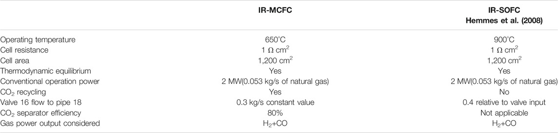
TABLE 1. Summary of assumptions made in this MCFC study.
Hydrogen Production Using IR-MCFCs
High temperature IR-MCFCs operate at about 650°C and produce heat from reversible and irreversible processes which are partly used for the reforming reaction of the fuel (mostly natural gas) to produce hydrogen. It is possible to obtain more hydrogen than necessary for the operation of the fuel cells by adjusting the operating conditions. In this section, the IR-MCFC model developed in Cycle-Tempo is briefly explained. Similar to the IR-SOFC reference system (Hemmes et al., 2008), our MCFC flowsheet system layout shown in Figure 1 was designed to be as simple as possible. This design has not been optimized in any way, not for high efficiency nor economically. The natural gas composition of the fuel was chosen to be the gas composition from the largest Dutch source “Slochteren” as it is selected to be the standard gas composition in the Netherlands. This low calorific gas was found to contain about 14% of nitrogen.
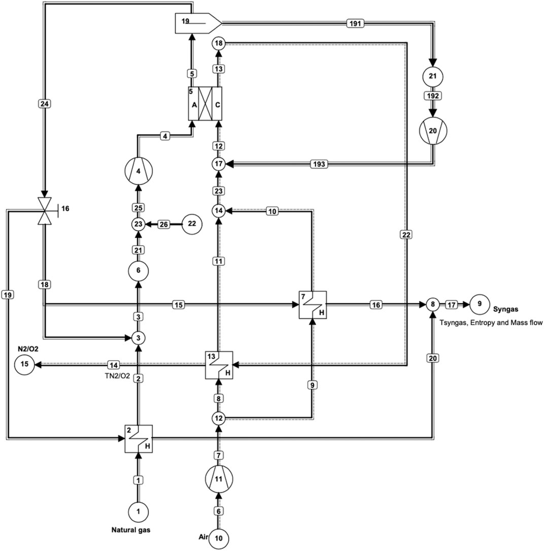
FIGURE 1. Cycle-Tempo flowsheet diagram of an internal reforming MCFC system for coproduction of hydrogen and power.
Recycle loops have been applied to the anode and the cathode as shown in Figure 1. In MCFCs, CO2 that is liberated at the anode needs to be recycled back to the cathode to provide the necessary CO2 for the cathode reaction next to the O2 in the air. This is done through the separator (apparatus 19) as shown in Figure 1. The role of the separator is to isolate CO2 from the anode output flow. The separator in this model has been assigned a separation efficiency of 80%.
In the SOFC model, there is no CO2 recycling; this is in fact the primary difference between the two fuel cells next to the difference in the operating temperature. Recycling has three main benefits. First, a better temperature distribution can be achieved inside a fuel cell stack because recycling provides the necessary heat for the endothermic reforming reaction in particular at the beginning of the cell (Hemmes et al., 2012a) [4]. This is beneficial as these reactions occur at rapid speeds; thus, they predominantly occur towards the inlet of the fuel cell stack. Secondly, the necessary steam required for the reforming reaction is also provided by recycling. Input gas streams are preheated by the output streams through various heat exchangers present in the model. Third, as already mentioned, CO2 recycling provides the CO2 required by the cathode in the MCFC operation. After CO2 removal, a part of the remaining gas from the anode output is recycled back to the anode and the rest of the syngas exits through sink 9. A valve (apparatus 16) determines the amount of gas exiting through sink 9 and the amount of gas being recycled into the anode. In this case with an IR-MCFC, the recycle value is set to 0.3 kg/s for all three modes of operation. This value was chosen to obtain results in all three modes of operation in the required range of fuel utilization values. For other values, no convergence could be obtained in running the program for some modes and/or operation parameters in the chosen value range of fuel utilization (0.6–0.95).
The output from pipe No. 17 contains hydrogen and other gases such as CO, CO2, and H2O. Hydrogen can be separated from this mixture, but that is excluded in this study. In order to stay consistent with the IR-SOFC model, only the amounts of hydrogen and CO are considered in the results, since they are the components of the fuel containing chemical energy and knowing that CO can be converted into hydrogen via the well-known shift reaction with steam. Their energy contents are added to give total useful gas output, in this study sometimes roughly referred to as “hydrogen” output. Nevertheless, most of the heating value of the off-gas is contributed by hydrogen, while CO contributes only about one-third. The IR-MCFC model shown in Figure 1 is used to examine the influence of changing fuel utilization in the fuel cell, gas input rate, cell voltage, and current density on the coproduction of power and hydrogen. In the model, apparatus 5 is the IR-MCFC that operates near atmospheric pressure. Natural gas and air are supplied through sources 1 and 10, respectively. Air from source 10 is compressed slightly by an air blower (apparatus 11). The natural gas from source 1 is already available at a slightly elevated pressure as it is in the gas distribution grid and does not need further compressing. A blower (apparatus 4) is needed to drive the anode recycle circuit and another one (apparatus 20) is used to drive the CO2 loop to the cathode. There are three heat exchangers in the model, two of which (Apparatuses 13 and 7) are used to heat the cathode inlet air, while the third (apparatus 2) is used to preheat the fuel flow. Fixed parameters include the fuel cell outlet temperature which is fixed at 700°C, cell resistance which is assumed to be 1 ohmcm2, and cell area which is set at 1200 cm2 to be consistent with the SOFC model of our earlier reference study.
Results and Comparison with IR-SOFC Study
In this section, the results obtained from the flowsheet calculations on the IR-MCFC system are presented in Figure 1. Three different modes of operations have also been explored in accordance with the IR-SOFC model in the reference study (Hemmes et al., 2008). In each mode, the fuel utilization is reduced from 95 to 60% to showcase the gradual shift from conventional power production (uf = 95%) to hydrogen and CO coproduction. Finally, to make the comparison between the two IR-FC models, the readings obtained from both models are plotted together in one figure for each mode of operation. Since the SOFC calculations were performed some years ago, they were repeated to have all the result data available for comparison with the MCFC system.
Efficiency definitions used in this article and in the graphs presented later are as follows:
Electric efficiency:
Gas efficiency:
Total efficiency:
In Equations 11, 12, 13, the variable Pin,system is the power input into the system through source 1 as shown in Figure 1; it is the MW equivalent of the natural gas that is entering the system per unit time. Pelec,fc is the electric power output from the fuel cell and Pgas,system is the H2+CO energy output from the system per unit time obtained at sink 9 as shown in Figure 1. The fuel utilization values considered in all three modes of operations refer to the fuel utilization in the fuel cell. It is important to note that in Pgas,system, we consider H2+CO because carbon monoxide can be easily used to produce hydrogen through the well-known water-gas shift reaction as shown in Eq. 14:
In this article, the H2+CO power output refers to the energy content in the moles per second of hydrogen and carbon monoxide obtained at sink 9 as shown in Figure 1. Power lost in separation of the gases at sink 9 and water-gas shift reaction have not been considered in efficiency calculations.
High-Efficiency Mode
In this mode of operation, the input fuel flow is kept constant at “2 MW equivalent” (0.053 kg/s at Source 1) in order to match the arbitrarily chosen fuel cell size in conventional operation. Next, in the simulations, the fuel utilization (uf) in the fuel cell is decreased in steps from 95 to 60% while keeping the total cell area constant as in the previous SOFC study (Hemmes et al., 2008). This results in a decrease in the current density from 1,586 to 1,343 A/m2 along with electric power between the uf of 95 and 60%. At very low utilization, it is possible that the fuel cell does not produce enough heat for the endothermic reforming reaction. Although in some cases a fuel utilization below 60% is possible, it is not considered in this study as such very low utilizations cannot be reached in all modes of operations.
While the current density decreases by reducing uf, the electric power does not decrease proportionally since Vcell increases simultaneously as indicated by Eq. 2. In Figure 2, a plot of the power output in the form of H2+CO and electric power vs. uf is shown. It can be seen that the slight decrease in electric power output from uf 95 to 60% is overcompensated by the increase in H2+CO power output. The electric output can be considered to be more or less constant. However, the total power output (not counting heat) is more than what can be attained in conventional fuel cell operation with only electric power output and overall efficiency of over 80% (at low fuel utilization uf = 60%) can be achieved as shown in Figure 3. As stated above the enthalpy carried by hydrogen is roughly twice that of CO.
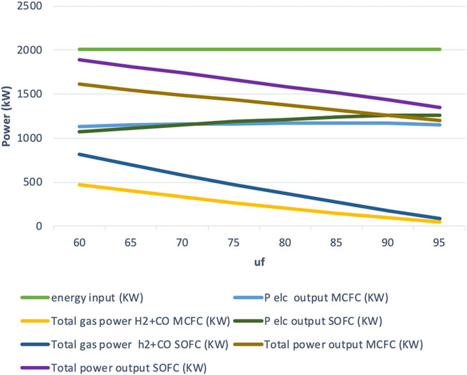
FIGURE 2. Power output vs. fuel utilization for high-efficiency mode.
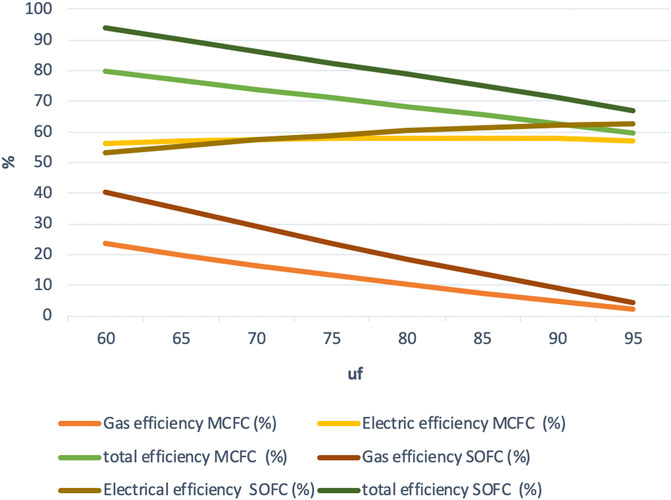
FIGURE 3. Efficiency vs. fuel utilization for high-efficiency mode.
Figure 3 shows a graph of efficiency vs. uf for the high-efficiency mode. Here, gas efficiency is defined as H2+CO power output divided by the power input. From the figure, it can be seen that the total efficiency increases at a higher rate than the decrease in electric power efficiency as uf decreases. There is a very slight decrease in the electric efficiency (about 59–56%), so it can be assumed to be almost constant in this case. This mode may be the most efficient, but it might not be the most economically favorable mode. From the calculations, it can also be determined that it is possible to trade power for hydrogen, but it is not a one-to-one trade-off. This means that the sum of electricity and hydrogen power is not constant. As the heat loss across the system boundary is greatly reduced, maximum total efficiency of 80% is obtained at 60% fuel utilization. It is important to note that this efficiency is the total efficiency for the production of hydrogen + power excluding heat, so not the total efficiency of all power output including heat, which is usually defined as total efficiency in CHP (fuel cell) systems.
As shown in Figure 2, at low fuel utilization of below 75% the IR-MCFC system produces higher electric power output than the IR-SOFC system. As the fuel utilization increases above 75%, the electric output from the IR-SOFC increases at a higher rate than IR-MCFC system, producing slightly higher electric power output at higher fuel utilization. The maximum electric efficiency achieved by the IR-MCFC is about 59% and, for the IR-SOFC, it is about 63%.
From Figures 2, 3, observations regarding the coproduction of H2/CO can also be made. The values of H2+ CO are represented as “total gas power” and “gas efficiency” in the graphs plotted for the fuel cells. As expected at low fuel utilization, the total gas power is higher as more H2/CO is produced at lower uf. At lower fuel utilization uf = 60%, the total gas power is much higher for the IR-SOFC system (816 kW) than it is for the IR-MCFC system (475 kW). At higher fuel utilization, as the fuel is almost completely utilized for producing electric power, the amount of H2/CO liberated from the fuel cell system diminishes.
The overall energy efficiency which has been calculated as the sum of electric efficiency and the total gas efficiency in this study is also plotted in Figure 3. There is a difference ranging from roughly 8 to 13 point%, with the increase in uf between the two fuel cell systems, and with the IR-SOFC model having higher overall efficiency throughout. The overall efficiency increases as the utilization decreases; thus, the maximum is achieved at the lowest utilization uf = 60%, being 93% for the IR-SOFC model and 80% for the IR-MCFC model.
From these observations, it can be concluded that, in the high-efficiency mode, in the range of observed fuel utilization values, the electric efficiencies of the IR-MCFC system are a little lower but similar to the electric efficiencies achieved by the IR-SOFC system. The overall efficiency, however, is much lower for the IR-MCFC system, which results from the significantly lower gas efficiency. Despite this, still, overall efficiency of over 80% is achieved with the IR-MCFC system.
Constant Current Mode
In the constant current mode, we keep the current density constant and the fuel utilization is decreased by increasing the natural gas input flow. The current density is kept constant at 1,500 A/m2 as it represents conventional operation at reasonable power density. In this mode, Cycle-Tempo is allowed to change the gas input flow to meet both the fixed values of uf and i. The results obtained in this mode are found to be in between high-power (see section High-Power Mode) and high-efficiency mode (see section High-Efficiency Mode). From Figure 5, it can be noticed that, in both fuel cell systems, the total efficiency increases with a decrease in uf. In order to keep the current density constant, the fuel cell systems require a higher fuel input at lower uf. As a result of higher fuel input, higher electric power outputs are also observed at lower fuel utilization. The electric efficiencies vary similarly to those of the high-efficiency mode with maximums of 57% (for IR-MCFC) and 62% (for IR-SOFC) occurring at uf = 95%.
The total gas power output for both the fuel cell systems is higher than what was obtained in the high-efficiency mode, because of the higher fuel input at lower fuel utilization. At uf = 60%, a total gas power output of 591 kW is obtained for the IR-MCFC, while the IR-SOFC system produces almost double this amount by generating 1,062 kW of gas power (see Figure 4). The variation of gas efficiency with uf gives a nearly identical plot to the one obtained in the high-efficiency mode (as seen from Figures 3, 5). Similarly, the overall efficiency is found to closely resemble the values from the high-efficiency mode as well. The maximum value of overall efficiency is 80% for the IR-MCFC, and 92% for the IR-SOFC is achieved again at the lowest fuel utilization we simulated, i.e., uf = 60%. This also holds in the constant current mode because just like in the high-efficiency mode, no compromise has been made in the electrical efficiency of the fuel cell systems. In other words, while fuel input is allowed to change to keep current density constant in this mode, a significant drop in electrical efficiency is not observed.
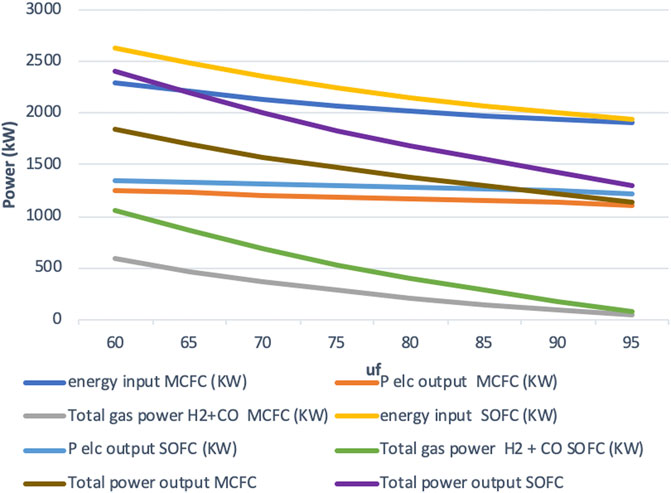
FIGURE 4. Power output vs. fuel utilization for constant current density mode.
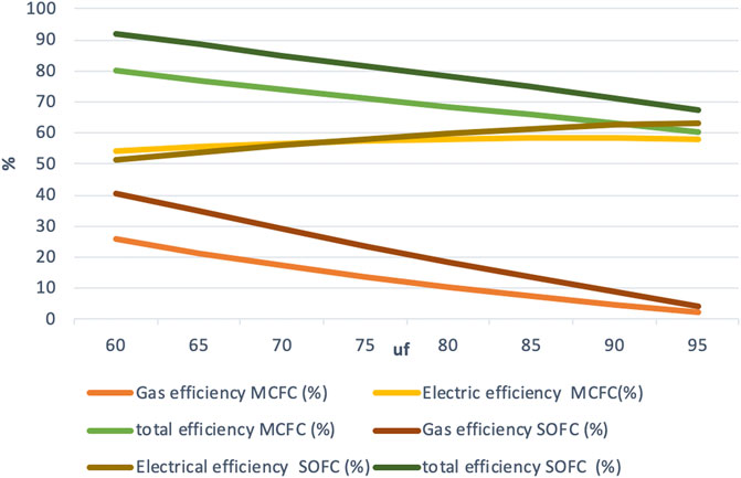
FIGURE 5. Efficiency vs. fuel utilization for constant current density mode.
To conclude, in this mode, maximum power output occurs at the lowest fuel utilization due to much higher fuel input. Just like in the high-efficiency mode, the electric efficiency of IR-MCFC is in the range of what is achieved by the IR-SOFC system. Again, the difference in the overall efficiency for the IR-MCFC system can be attributed to the lower gas efficiency in the MCFC system. But the IR-MCFC system was still able to achieve an overall efficiency of 80%.
High-Power Mode
High-power mode is of great interest from an economic point of view. In this mode, large current densities are obtained by keeping the cell voltage fixed at a very low value. Similar to the constant current mode, this mode achieves a decrease in fuel utilization uf by increasing the natural gas input fuel flow. As the cell voltage is low (set at 0.5 V), the current density is high and so is the amount of heat dissipated. This heat can be used for the internal reforming reaction of the natural gas fuel, and a larger quantity of natural gas can be reformed than in previous modes. But it is also necessary to have a larger fuel input to provide enough electrons for the larger current. The results for this mode of operation are shown in Figure 6 (power output vs. fuel utilization) and Figure 7 (efficiency vs. fuel utilization). As very high-power output values are obtained in this mode, this is an extreme operation mode.
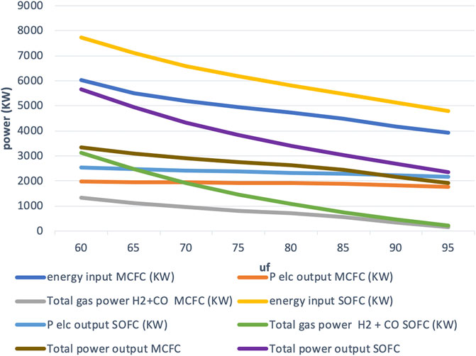
FIGURE 6. Power output vs. fuel utilization for high-power mode.
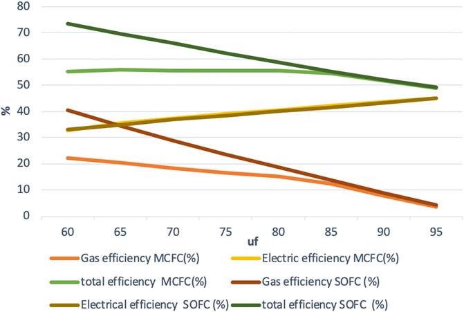
FIGURE 7. Efficiency vs. fuel utilization for high-power mode.
Although the cell voltage is lower than in the other modes, the current increases so much more that still a significantly larger electric power output (current times cell voltage) is achieved in this mode. This increase in power output can be seen in Figure 6, where at uf = 60%, the current density was found to be i = 3,428 A/m2. In this high-power mode, cell operation is carried out near the maximum in the power output vs. current density curve at the expense of a lower electric efficiency (Hemmes et al., 2008). By using waste heat for producing hydrogen, we can operate at or near maximum power for electricity production while at the same time producing a similar high output in the form of H2/CO albeit at the expense of a drop in efficiency compared to the two modes described above. At low uf, low electric power output is partly compensated by the higher H2/CO production, and the total efficiency for coproduction of gas and electric power was found to reach 56%. It is seen that the maximum electric power output obtained in the high-efficiency mode (1,153 kW) is 58% of that obtained in the high-power mode (1,980 kW). So, roughly estimating, it can be said that the high-power mode produces electric output that is almost twice that of the high-efficiency mode. Additionally, 1,344 kW of H2+CO gas power output is obtained in this mode, bringing the total useful output to over 3,300 kW. This is 2.9 or about 3 times the electric power output obtained in the conventional operation (1,153 kWe) carried out with the same fuel cell.
It should be noted that although, at low fuel utilization, the system is in H2/CO production mode, the electric power output increases as well as the gas output. This is because, in this mode of operation, the utilization factor is decreased by increasing the natural gas input. Hence, by allowing more Joules per second to flow into the system, we are increasing both hydrogen production and electric power output. Moreover, Nernst loss is significantly reduced due to higher partial pressure of hydrogen in particular at the output side of the fuel cell at lower fuel utilization, resulting in an improvement of cell voltage and thus fuel efficiency as indicated by Eq. 2.
The electric efficiency increases with an increasing fuel utilization, but it is much lower than in the other two modes. The electric efficiency varies almost identically between 32 and 45% for both the fuel cell systems as the fuel utilization increases as shown in Figure 7.
The difference in gas efficiency between the two fuel cell systems is much larger at lower fuel utilization and is almost the same beyond uf = 85%. Just like in the other two modes of operation, the maximum gas efficiency remains around 25% for the IR-MCFC system and 40% for the IR-SOFC system.
The maximum total efficiency of the IR-MCFC system is found to be over 56% while for the IR-SOFC model, it is found to be about 73%. The maximum total output from the IR-MCFC system is 3,325, and 5,667 kW for the IR-SOFC system. Although outputs as high as those for the IR-SOFC system may not be obtainable with the IR-MCFC system used here, we see that the maximum total output from the IR-MCFC system can still be almost three times higher compared to conventional operation.
Therefore, this operation mode might be the most economic one providing a three times higher production rate of valuable economic goods (electricity and hydrogen) for the same capital cost of the same fuel cell stack, provided the course that the stack can handle the higher gas flows and higher current densities and that the electrodes are still stable at a low cell voltage of around 0.5 V.
Gas Composition of the Output Gas
As the fuel utilization value is varied from uf = 60% to uf = 95%, the composition of gases in the MCFC output changes as shown in Figure 8 for the high-power mode similar to what has been shown for the SOFC model (Hemmes et al., 2008). The anode output is found to contain a gas mixture containing H2, CO, H2O, and CO2 with an obvious decrease in H2 and CO as the fuel utilization increases. The cathode output mainly consists of a mixture of N2 and O2 (N2 is not shown in Figure 8). The gas output compositions are mostly similar to those obtained from the IR-SOFC model; however, a major difference was observed at the anode side involving a much higher CO2 flow for the MCFC. This is expected due to the difference in the fuel cell operating principles. In a SOFC, which operates at much higher temperatures of up to 1,000°C, the charge carriers are the O2- ions, while in the MCFC operating here at 650°C, the charge carriers are the CO32- ions. These CO32- ions travel from cathode to anode through the electrolyte, while the electrons travel from anode to cathode in an external circuit. As a result of this, a higher CO2 concentration is found at the anode of an MCFC. It is important to note that the high concentration of CO2 in the anode output is not reflected in the gas collected at sink 9 in Figure 1 as the CO2 in the anode output is required by the cathode. The CO2 is separated and recirculated from the anode output to the cathode input with a recycle loop as shown in Figure 1.
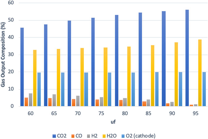
FIGURE 8. Main gas output composition vs. utilization factor for high-power mode at the MCFC output.
Cycle-Tempo also provides the exergy efficiency of the fuel cell systems. For the high-efficiency mode and the constant current density mode, the maximum exergy efficiency observed from the IR-SOFC system was about 59% while the IR-MCFC system achieved a maximum of about 54%. In the high-power mode, the system exergy efficiency was also found to be closely identical in both the fuel cell systems and it was found to vary in the range between 30 and 40%.
A comparison of results between the two fuel cells at fuel utilization (uf) of 60% where overall efficiency is much higher than conventional fuel cell operation has been presented in Table 2.
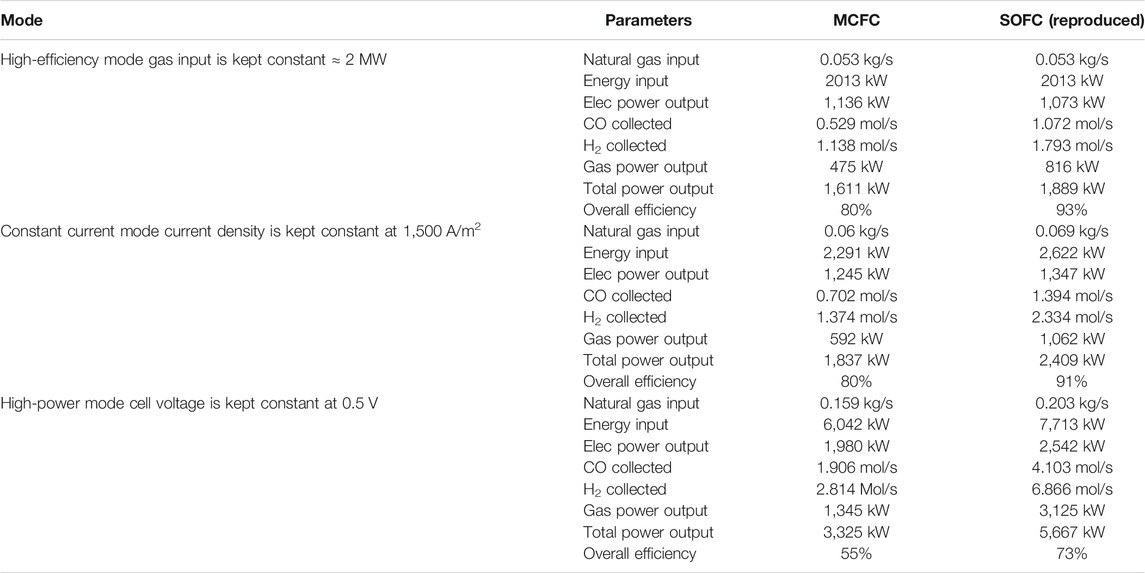
TABLE 2. Comparison of results between the two fuel cells at fuel utilization (uf) of 60% where the overall efficiency is much higher than conventional fuel cell operation. The results for SOFC have been reproduced based on information provided in Hemmes et al. (2008).
Reasons for Loss in Efficiency in IR-MCFC
Comparing the two fuel cell systems it was found that the electric efficiencies were closer to each other than the gas efficiencies for all three modes of operation. The difference in overall efficiencies between the two fuel cell systems is therefore primarily due to differences in gas efficiency. While the IR-SOFC system can achieve a gas efficiency of up to 40%, the IR-MCFC system examined in this study was able to achieve only 25% at best. While care has been taken to keep the parameters in MCFC as close as possible to the SOFC reference study, there are a few differences in the operating principles, system parameters, and models. It should be noted that the operating parameters of the two fuel cells are different. The IR-MCFC system is kept at 650°C while the IR-SOFC is kept at 900°C. From Figure 8, we also see that while operating in the high-power mode (also true for other modes), the anode output gas composition obtained from the IR-MCFC system contains a much higher CO2 concentration than in the IR-SOFC system, which on the other hand is much richer in steam. This is due to the difference in the operation of the two IR-FCs systems and the reactions taking place in the fuel cells due to the need for CO2 at the cathode of an MCFC, whereas the SOFC only needs air.
In the MCFC model as shown in Figure 1, CO2 generated in the anode output is recycled to the cathode through a separator (apparatus 19). The separation efficiency of the separator is set at 80%. The CO2 that is separated is compressed in a blower (apparatus 20) in the recycle loop to provide CO2 at the pressure of the air entering the cathode.
The remaining gas of the anode outlet is made to pass through the valve (apparatus16), where a portion of the gas is injected into the fuel stream through pipe 18. The remaining gas from the valve passes through heat exchangers (apparatus 2 and apparatus 7) through pipes 19 and 15, respectively. These two streams after passing through heat exchangers ultimately combine at the end to supply hydrogen and CO from the outlet of pipe 17. This arrangement through the valve is nearly identical to the SOFC model. The main difference is that in the case of the SOFC model, the input flow to pipe 18 is fixed at 0.4 relative to pipe 5 (anode outlet). This means that 40% of the anode output is injected back into the fuel stream headed to the anode inlet. The recycling into the anode inlet is needed to provide sufficient steam for the internal reforming reaction. Due to the complexity arising from the recycle loop for CO2 from anode output to cathode, a similar flow division cannot be specified for pipe 18 in this Cycle-Tempo MCFC model. The other option for specifying input data for a pipe (pipe 18 in this case) that is leaving a valve is by fixing its absolute flow. In the MCFC model, the flow for pipe 18 is set to a fixed value of 0.3 kg/s. This is a “best fit” value chosen to operate in all three modes, across the entire range of fuel utilization values analyzed. In hindsight, this appears to be a quite high value possibly causing or at least contributing to the lower efficiencies for the MCFC system. It is to be compared for example with the input flow of natural gas fuel of 0.053 kg/s at Source 1.
Due to fixing the flow in pipe 18 to 0.3 kg/s, the majority of the gas from the anode (after CO2 separation) is actually recycled into the fuel stream towards the anode inlet. This means much more of the anode output in comparison to the IR-SOFC is actually getting recycled back into the anode input in the case of IR-MCFC. This stream is rich in hydrogen and thus supplies additional fuel to the IR-MCFC along with the natural gas which is entering the system. By looking at the high-efficiency mode where fuels entering the system is constant and analyzing the power outputs, it would imply that the IR-SOFC configuration is more efficient. The remaining gas constitutes the syngas production at sink 9 as shown in Figure 1, which is lower for all fuel utilization values in IR-MCFC than IR-SOFC. By definition with the increased fuel utilization in the fuel cell, H2/CO in the anode outlet decreases; this results in the gas power output line of IR-MCFC in the graph (e.g., Figure 2) approaching zero. In the case of IR-MCFC, the amount of natural gas fuel entering the system in the constant current density mode and the high-power mode is less than in the IR-SOFC systems for all utilization factors. As either the current density value or the voltage in these modes is fixed in the fuel cell, the variation in the amount of fuel may be due to the difference in the amount of hydrogen from valve 16 being recycled in the anode input in the two fuel cell systems. This difference in the fuel input can be as high as 1,700 KW equivalent to that in the high-power mode operating at fuel cell utilization of uf = 60%. With a lower amount of fuel entering the fuel cells, outputs lower than IR-SOFC can be expected. Moreover, there are two other blowers, one (apparatus 4) before the anode inlet that provides pressurized fuel mixture to the anode and the other (apparatus 11) that compresses the air entering the system. As a result of the much higher flow in pipe 18, the flow through the blower 4 is larger in the MCFC model (than the SOFC model), requiring more power for compression than in the SOFC model. Due to the increased mass flow into the anode of the fuel cell, both anode and cathode outputs are larger as well. The mass flow from the cathode output is at a high temperature (700°C) and it passes through a heat exchanger (apparatus 13) before exiting through sink 15 at a reduced temperature of 100°C, which is a lower exiting temperature than the cathode exhaust in the IR-SOFC model. As a result of the large amount of heat available at (heat exchanger) apparatus 13, there is an increased airflow into the system through compressor 11. This air is ultimately supplied to the cathode inlet. This results in higher power consumption in the IR-MCFC system than in the IR-SOFC case for blower 11.
With an additional blower (apparatus 20) for separated CO2, along with the higher power consumption by the other two compressors (apparatuses 4 and 11), the power consumed by the auxiliary components of the system is much higher than in the SOFC case, resulting in additional loss of efficiency in the IR-MCFC systems as well.
Conclusion
It was found through flow sheet calculations on an IR-MCFC system that it is possible to design a coproduction system that can function in a conventional mode producing mainly electric power and heat and in coproduction mode producing electric power, hydrogen, and very little heat. By using waste heat in the endothermic reforming reaction to produce hydrogen, high total efficiency of over 80% for hydrogen + power production is possible. As waste heat is effectively utilized in the production of hydrogen, the IR-MCFC can be operated at a very high power density. In the high-power mode, it is possible to achieve a very high electric power output that is nearly twice that of the same MCFC when operated in a conventional mode, while at the same time, an additional large amount of power in the form of hydrogen is coproduced. The total efficiency, however, drops below 60% in this high-power mode.
• High-efficiency mode: IR-MCFC achieved a maximum total efficiency of over 80% for electricity plus hydrogen production.
• Constant current density mode: IR-MCFC also achieved a maximum total (gas plus power) efficiency of over 80%.
• High-power mode: IR-MCFC achieved a maximum overall efficiency of over 56% at a total (gas plus power) output three times higher than in the high-efficiency mode.
In comparison to the IR-SOFC system, the IR-MCFC system produces similar electric output at similar efficiency but with the gas power output in the form of hydrogen and CO; hence, the gas efficiency is much lower. This results in lower total efficiency. In all three modes of operation, the IR-MCFC overall efficiency was at least 10 percentage points lower than the IR-SOFC model. The gas efficiencies may be lower due to reasons associated with operating principles, valve recycling ratio setting, and increased power consumption by the blowers. Despite this, IR-MCFC, like the IR-SOFC system, allows for a flexible operation of a coproduction system that can meet varying hydrogen demand and electric demands at high efficiencies, thus making them technically feasible for poly-generation applications.
Data Availability Statement
The original contributions presented in the study are included in the article/Supplementary Material, further inquiries can be directed to the corresponding authors.
Author Contributions
The research that forms the basis for this article was performed by US as part of his MSc-thesis work at TU Delft under the supervision of KH as a follow-up on the simulation work performed by Anish Patil also under the supervision of KH. US also wrote the first concept of this article, further commented and discussed in the usual iterative process by KH and US after the graduation of US.
Funding
This research was performed funded by the regular educational funds of TU Delft (“first money stream”) without external funding.
Conflict of Interest
The authors declare that the research was conducted in the absence of any commercial or financial relationships that could be construed as a potential conflict of interest.
Publisher’s Note
All claims expressed in this article are solely those of the authors and do not necessarily represent those of their affiliated organizations, or those of the publisher, the editors and the reviewers. Any product that may be evaluated in this article, or claim that may be made by its manufacturer, is not guaranteed or endorsed by the publisher.
Supplementary Material
The Supplementary Material for this article can be found online at: https://www.frontiersin.org/articles/10.3389/fenrg.2021.656490/full#supplementary-material
Footnotes
1Cycle-Tempo is now distributed by Asimptote (www.asimptote.nl/software/cycle-tempo/).
2Cycle-Tempo operation guide and technical notes (http://www.asimptote.nl/software/cycle-tempo/cycle-tempo-documentation/).
References
Abdalla, A. M., Hossain, S., Petra, P. M., Ghasemi, M., and Azad, A. K. (2018). Achievements and Trends of Solid Oxide Fuel Cells in Clean Energy Field: A Perspective Review. Front. Energ. 14 (2), 359–382. doi:10.1007/s11708-018-0546-2
Adams, T. A., Nease, J., Tucker, D., and Barton, P. I. (2012). Energy Conversion With Solid Oxide Fuel Cell Systems: A Review of Concepts and Outlooks for the Short- and Long-Term. Ind. Eng. Chem. Res. 52 (9), 3089–3111. doi:10.1021/ie300996r
Afif, A., Radenahmad, N., Cheok, Q., Shams, S., Kim, J. H., and Azad, A. K. (2016). Ammonia-fed Fuel Cells: a Comprehensive Review. Renew. Sustainable Energ. Rev. 60, 822–835. doi:10.1016/j.rser.2016.01.120
Au, S. F., Peelen, W. H. A., Standaert, F. R. A. M., Hemmes, K., and Uchida, I. (2001). Verification of Analytical Fuel Cell Models by Performance Testing at a 110 Cm2 Molten Carbonate Fuel Cell. J. Electrochem. Soc. 148 (10), A1051. doi:10.1149/1.1396335
Au, S. F., Woudstra, N., Hemmes, K., and Uchida, I. (2003). Verification of a Simple Numerical Fuel Cell Model in a FlowSheeting Program by Performance Testing of a 110 Cm2 Molten Carbonate Fuel Cell. Energ. Convers. Management. 44 (14), 2297–2307. doi:10.1016/s0196-8904(02)00253-4
Baldi, F., Wang, L., Pérez-Fortes, M., and Maréchal, F. (2019). A Cogeneration System Based on Solid Oxide and Proton Exchange Membrane Fuel Cells with Hybrid Storage for Off-Grid Applications. Front. Energ. Res. 6, 1–18. doi:10.3389/fenrg.2018.00139
Chen, B., Xu, H., Sun, Q., Zhang, H., Tan, P., Cai, W., et al. (2018). Syngas/Power Cogeneration From Proton Conducting Solid Oxide Fuel Cells Assisted by Dry Methane Reforming: A Thermal-Electrochemical Modelling Study. Energ. Convers. Management. 167, 37–44. doi:10.1016/j.enconman.2018.04.078
Dogdibegovic, E., Fukuyama, Y., and Tucker, M. (2020). Ethanol Internal Reforming in Solid Oxide Fuel Cells: A Path toward High Performance Metal-Supported Cells for Vehicular Applications [Journal of Power Sources 449 (2020) 227598]. J. Power Sourc. 492, 229644. doi:10.1016/j.jpowsour.2021.229644
Escudero, M. J., Maffiotte, C. A., and Serrano, J. L. (2021). Long-Term Operation of a Solid Oxide Fuel Cell with MoNi-CeO2 as Anode Directly Fed by Biogas Containing Simultaneously Sulphur and Siloxane. J. Power Sourc. 481, 229048. doi:10.1016/j.jpowsour.2020.229048
European Commission (2021). Cogeneration of Hydrogen and Power Using Solid Oxide Based System Fed by Methane Rich Gas. Grant Agreement ID: 735692. Retrieved from https://cordis.europa.eu/project/id/735692 (Accessed March 23, 2021).
Fernandes, A., Woudstra, T., van Wijk, A., Verhoef, L., and Aravind, P. V. (2016). Fuel Cell Electric Vehicle as a Power Plant and SOFC as a Natural Gas Reformer: An Exergy Analysis of Different System Designs. Appl. Energ. 173, 13–28. doi:10.1016/j.apenergy.2016.03.107
Fuel Cell Handbook (2004). Fuel Cell Handbook. Morgantown, WV: U.S. Dept. of Energy, National Energy Technology Laboratory, Strategic Center for Natural Gas.
Guerrero, J., Blaabjerg, F., Zhelev, T., Hemmes, K., Monmasson, E., Jemei, S., et al. (2010). Distributed Generation: Toward a New Energy Paradigm. EEE Ind. Electron. Mag. 4 (1), 52–64. doi:10.1109/mie.2010.935862
Hemmes, K. (2004). “Fuel Cells,” in In Modern Aspects of Electrochemistry (Springer US), 131–251. doi:10.1007/978-1-4419-9027-3_4
Hemmes, K. (2010). Chapter 10. Hydrogen Production by Internal Reforming Fuel Cells. Innov. Fuel Cell Tech. Energ. Environ. Ser., 287–305. doi:10.1039/9781849732109-00287
Hemmes, K. (2013). Securing Energy Supply II: Diversification of Energy Sources and Carriers. Int. Handbook Energ. Security., 133–145. doi:10.4337/9781781007907.00017
Hemmes, K. (2015). Exploring New Production Methods of Hydrogen/Natural Gas Blends. Enriched Methane Green. Energ. Technology., 215–234. doi:10.1007/978-3-319-22192-2_12
Hemmes, K. (2016). Innovative Membrane Induced Functionalities of Fuel Cells. Int. J. Hydrogen Energ. 41 (41), 18837–18845. doi:10.1016/j.ijhydene.2016.06.131
Hemmes, K., Barbieri, G., Lee, Y. M., Drioli, E., and De Wit, H. (2012a). Process Intensification and Fuel Cells Using a Multi-Source Multi-Product Approach. Chem. Eng. Process. Process Intensification. 51, 88–108. doi:10.1016/j.cep.2011.09.010
Hemmes, K., Guerrero, J. M., and Zhelev, T. (2012b). Highly Efficient Distributed Generation and High-Capacity Energy Storage. Chem. Eng. Process. Process Intensification. 51, 18–31. doi:10.1016/j.cep.2011.09.012
Hemmes, K., Houwing, M., and Woudstra, N. (2010). Modeling of a Methane Fuelled Direct Carbon Fuel Cell System. J. Fuel Cell Sci. Technology. 7 (6), 061008. doi:10.1115/1.4001016
Hemmes, K., Kamp, L. M., Vernay, A. B. H., and de Werk, G. (2011). A Multi-Source Multi-Product Internal Reforming Fuel Cell Energy System as a Stepping Stone in the Transition towards a More Sustainable Energy and Transport Sector. Int. J. Hydrogen Energ. 36 (16), 10221–10227. doi:10.1016/j.ijhydene.2010.11.017
Hemmes, K., Patil, A., and Woudstra, N. (2008). Flexible Coproduction of Hydrogen and Power Using Internal Reforming Solid Oxide Fuel Cells System. J. Fuel Cell Sci. Technology. 5 (4), 041010. doi:10.1115/1.2931459
Leal, E. M., and Brouwer, J. (2006). A Thermodynamic Analysis of Electricity and Hydrogen Co-production Using a Solid Oxide Fuel Cell. J. Fuel Cell Sci. Technology. 3 (2), 137–143. doi:10.1115/1.2173669
Leo, A. (2016). Tri-generation Fuel Cells: Opening Doors to Distributed Hydrogen Markets – Cryogas International. Retrieved from https://www.fuelcellenergy.com/tri-generation-fuel-cells-opening-doors-to-distributed-hydrogen-markets-cryogas-international/ (Accessed August 28, 2020).
Li, X., Ogden, J., and Yang, C. (2013). Analysis of the Design and Economics of Molten Carbonate Fuel Cell Tri-generation Systems Providing Heat and Power for Commercial Buildings and H2 for FC Vehicles. J. Power Sourc. 241, 668–679. doi:10.1016/j.jpowsour.2013.04.068
Margalef, P., Brown, T., Brouwer, J., and Samuelsen, S. (2011). Conceptual Design and Configuration Performance Analyses of Polygenerating High Temperature Fuel Cells. Int. J. Hydrogen Energ. 36 (16), 10044–10056. doi:10.1016/j.ijhydene.2011.05.072
Mclarty, D., and Brouwer, J. (2014). Poly-generating Closed Cathode Fuel Cell with Carbon Capture. Appl. Energ. 131, 108–116. doi:10.1016/j.apenergy.2014.06.011
Nguyen, V. N., Blum, L., and Peters, R. (2014). Operational Behavior and Reforming Kinetics over Ni/YSZ of a Planar Type Pre-reformer for SOFC Systems. Int. J. Hydrogen Energ. 39 (13), 7131–7141. doi:10.1016/j.ijhydene.2014.02.140
Panagi, K., Laycock, C. J., Reed, J. P., and Guwy, A. J. (2019). Highly Efficient Coproduction of Electrical Power and Synthesis Gas from Biohythane Using Solid Oxide Fuel Cell Technology. Appl. Energ. 255, 113854. doi:10.1016/j.apenergy.2019.113854
Pérez-Fortes, M., Mian, A., Srikanth, S., Wang, L., Diethelm, S., Varkaraki, E., et al. (2019). Design of a Pilot SOFC System for the Combined Production of Hydrogen and Electricity Under Refueling Station Requirements. Fuel Cells. 19, 389-407. doi:10.1002/fuce.201800200
Perna, A., Minutillo, M., Jannelli, E., Cigolotti, V., Nam, S. W., and Han, J. (2018). Design and Performance Assessment of a Combined Heat, Hydrogen and Power (CHHP) System Based on Ammonia-Fueled SOFC. Appl. Energ. 231, 1216–1229. doi:10.1016/j.apenergy.2018.09.138
Peters, R., Deja, R., Blum, L., Pennanen, J., Kiviaho, J., and Hakala, T. (2013). Analysis of Solid Oxide Fuel Cell System Concepts with Anode Recycling. Int. J. Hydrogen Energ. 38 (16), 6809–6820. doi:10.1016/j.ijhydene.2013.03.110
Ramadhani, F., Hussain, M. A., Mokhlis, H., Fazly, M., and Ali, J. M. (2019). Evaluation of Solid Oxide Fuel Cell Based Polygeneration System in Residential Areas Integrating with Electric Charging and Hydrogen Fueling Stations for Vehicles. Appl. Energ. 238, 1373–1388. doi:10.1016/j.apenergy.2019.01.150
Rinaldi, G., Mclarty, D., Brouwer, J., Lanzini, A., and Santarelli, M. (2015). Study of CO 2 Recovery in a Carbonate Fuel Cell Tri-generation Plant. J. Power Sourc. 284, 16–26. doi:10.1016/j.jpowsour.2015.02.147
Ru, Y., Sang, J., Xia, C., Wei, W.-C. J., and Guan, W. (2020). Durability of Direct Internal Reforming of Methanol as Fuel for Solid Oxide Fuel Cell with Double-Sided Cathodes. Int. J. Hydrogen Energ. 45 (11), 7069–7076. doi:10.1016/j.ijhydene.2019.12.222
Shaffer, B., and Brouwer, J. (2014). Feasibility of Solid Oxide Fuel Cell Dynamic Hydrogen Coproduction to Meet Building Demand. J. Power Sourc. 248, 58–69. doi:10.1016/j.jpowsour.2013.08.144
Standaert, F., Hemmes, K., and Woudstra, N. (1996). Analytical Fuel Cell Modeling. J. Power Sourc. 63 (2), 221–234. doi:10.1016/s0378-7753(96)02479-2
Verda, V., and Nicolin, F. (2010). Thermodynamic and Economic Optimization of a MCFC-Based Hybrid System for the Combined Production of Electricity and Hydrogen. Int. J. Hydrogen Energ. 35 (2), 794–806. doi:10.1016/j.ijhydene.2009.10.104
Vollmar, H., Maier, C., Nölscher, C., Merklein, T., and Poppinger, M. (2000). Innovative Concepts for the Coproduction of Electricity and Syngas with Solid Oxide Fuel Cells. J. Power Sourc. 86 (1-2), 90–97. doi:10.1016/s0378-7753(99)00421-8
Keywords: fuel cell, SOFC, MCFC, hydrogen, internal reforming, coproduction
Citation: Shikhar U, Hemmes K and Woudstra T (2021) Exploring the Possibility of Using Molten Carbonate Fuel Cell for the Flexible Coproduction of Hydrogen and Power. Front. Energy Res. 9:656490. doi: 10.3389/fenrg.2021.656490
Received: 20 January 2021; Accepted: 09 July 2021;
Published: 24 August 2021.
Edited by:
Barbara Bosio, University of Genoa, ItalyReviewed by:
Jakub Kupecki, Institute of Power Engineering, PolandMassimiliano Della Pietra, Italian National Agency for New Technologies, Energy and Sustainable Economic Development (ENEA), Italy
Timothy A. Barckholtz, ExxonMobil, United States
Copyright © 2021 Shikhar, Hemmes and Woudstra. This is an open-access article distributed under the terms of the Creative Commons Attribution License (CC BY). The use, distribution or reproduction in other forums is permitted, provided the original author(s) and the copyright owner(s) are credited and that the original publication in this journal is cited, in accordance with accepted academic practice. No use, distribution or reproduction is permitted which does not comply with these terms.
*Correspondence: Utkarsh Shikhar, dXNoaWtoYXI3QGdtYWlsLmNvbQ==; Kas Hemmes, aWp6cmtoZW1tZXNAZ21haWwuY29t