 Shengyu Liu
 Rong Liu
 Chengjie Qiu
 Wenzhong Zhou2,3
- 1School of Electric Power, South China University of Technology, Guangzhou, China
- 2Department of Mechanical Engineering, City University of Hong Kong, Kowloon, Hong Kong
- 3Center for Advanced Nuclear Safety and Sustainable Development, City University of Hong Kong, Kowloon, Hong Kong
Using the finite element multiphysics modeling method, the performance of the thorium-based fuel with Cr-coated SiC/SiC composite cladding under both normal operating and accident conditions was investigated in this work. First, the material properties of SiC/SiC composite and chromium were reviewed. Then, the implemented model was simulated, and the results were compared with those of the FRAPTRAN code to verify the correctness of the model used in this work. Finally, the fuel performance of the Th0.923U0.077O2 fuel, Th0.923Pu0.077O2 fuel, and UO2 fuel combined with the Cr-coated SiC/SiC composite cladding and Zircaloy cladding, respectively, was investigated and compared under both normal operating and accident conditions. Compared with the UO2 fuel, the Th0.923U0.077O2 and Th0.923Pu0.077O2 fuels were found to increase the fuel centerline temperature under both normal operating and reactivity-initiated accident (RIA) conditions, but decrease the fuel centerline temperature under loss-of-coolant accident (LOCA) condition. Moreover, compared to the UO2 fuel with the Zircaloy cladding, thorium-based fuels with Cr-coated SiC/SiC composite cladding were found to show better mechanical performance such as delaying the failure time by about 3 s of the Cr-coated SiC/SiC composite cladding under LOCA condition, and reducing the plenum pressure by about 0.4 MPa at the peak value in the fuel rod and the hoop strain of the cladding by about 16% under RIA condition.
Introduction
Thorium was considered as a potential alternative fuel since the beginning of nuclear energy development, and it is also found to have potential to stretch nuclear fuel reserves due to its natural abundance and because it is possible to breed the 232Th isotope into a fissile fuel (233U) (Ade et al., 2016). Thorium-based fuel is steadily gaining interest in the nuclear industry due to its advantageous thermal and chemical properties and low actinide production (Sokolov et al., 2005). Moreover, by using thorium–plutonium–based fuels, the stockpile of the reactor grade plutonium can be minimized compared to that resulting from the uranium dioxide fuel (Galahom, 2017). All technical parameters obtained from the studies on the thorium fuel cycle during the last 50 years indicate that the thorium fuel cycle can be used in most of reactor types already operated (Ünak, 2000). Then, Long. (2002) found that the thorium-based fuel had better performance than the UO2 fuel at a high fuel burnup by the FRAPCON-3 code, with a fission gas release model implemented into the code. The reactivity and plutonium isotopic concentrations of thorium-based fuel were also studied and compared to those of uranium-based fuel by Weaver and Herring (2002), and the further research of thorium-based fuel presented by Weaver and Herring (2003) indicated that thorium-based fuel for plutonium incineration is superior than that of uranium-based fuel and should be considered as an alternative to traditional MOX fuel in both current and future reactor designs. From a neutronics standpoint, feasibility of the use of thorium-based fuel in a PWR was further proved by Tucker and Usman (2018). Furthermore, a neutronic investigation of thorium-based fuel was performed by Kabach et al. (2020), which gave the conclusion that the specific (Th0.75, U0.25)O2 fuel could be used in the TRIGA Mark-II reactor.
Recently, silicon carbide fiber–reinforced silicon carbide matrix (SiC/SiC) composite was studied by several researchers as it was reported to have some better properties than Zircaloy cladding, such as the creep and oxidation resistance (Gulbransen and Jansson, 1972; Carter et al., 1984). The applications of SiC/SiC and C/SiC composite materials in many in-core components of light-water reactors (LWRs) and SiC/SiC composite cladding fabrication and performance evaluation were introduced by Akira (Kohyama and Hirotatsu, 2013). Then, Katoh et al. (2014a) pointed out that some basic understanding of the foundations for the design-limiting phenomena including constitutive theories for physical, thermal, mechanical, and fracture properties is needed. After that, Deck et al. (2015) used a representative SiC/SiC tube to present characterization methods for evaluating four distinct cladding metrics. Besides, Frazer et al. (2015) studied the localized mechanical property assessment of SiC/SiC composite, and the results indicated that nanoindentation can be used to test the individual components of a composite and evaluate its mechanical properties. Besides, the burnup parameters (keff, neutron, and so on) of SiC, VC, and ZrC were evaluated and compared with those of Zircaloy material by the SERPENT code (Korkut et al., 2016). In addition, neutron calculations for americium mixed fuels with Zircaloy-2, SiC, and VC were compared in the designed BWR system, which was made using the Monte Carlo (MCNPX) method (Düz, 2021). Moreover, the performance of the fuel with SiC/SiC composite cladding in the LWR was studied by several codes. A multimodule framework for analysis of the in-pile performance of fuel with SiC/SiC composite cladding concepts in LWRs was formulated by Ben-Belgacem et al. (2014), which gave some design considerations for SiC/SiC composite cladding. Then, using the BISON code, a foundation for the 3D thermomechanical sensitive analysis of SiC/SiC composite cladding with a series of simplified boundary conditions was investigated by Singh et al. (2018), and the results showed that besides elastic modulus, stress distribution was found to be highly sensitive not only to the thermal conductivity of SiC/SiC composite but also to the elastic modulus of the material. Furthermore, Liu et al. (2020) used the CAMPUS code based on COMSOL platform to simulate the fuel performance of thorium-based fuel with a two-layer SiC cladding, which showed better performances than that of UO2 fuel with the Zircaloy cladding.
However, under accident conditions, the coolant temperature near the cladding will be very high, which may cause the high-temperature steam oxidation of the SiC/SiC composite cladding. Chromium and its alloys are reported to have the characteristics of high melting point (Massalski et al., 1991) and good corrosion resistance Eck et al. (1989). Using the chromium coating technology to coat the outer surface of the cladding can effectively slow down the corrosion of the cladding outer surface. As reported by Lee et al. (2019), Cr-coated SiC/SiC composite, chemical vapor–deposited SiC, and pure Cr metal were oxidized in 100% steam at an atmospheric pressure for 4 h using a thermogravimetric analyzer, and the result indicated that the Cr coating layer does not adversely affect the silicon carbide substrate under these conditions. Moreover, a 2D axisymmetric model of a fuel rodlet with discrete fuel pellets was built and used to simulate the performance of the UO2 fuel with Zircaloy-4 cladding, Cr-coated Zircaloy cladding, and Cr-coated SiC/SiC composite cladding, as designed by Wagih et al. (2018). Inspired by the work of Liu et al. (2020), in this work, UO2 fuel with the Zircaloy cladding and thorium-based fuels (including Th0.923U0.077O2 and Th0.923Pu0.077O2) with the Cr-coated SiC/SiC composite cladding are selected to be investigated and compared under both normal operating and accident conditions by the CAMPUS code. The CAMPUS code, developed by Liu et al. (2016), which is based on the COMSOL platform, is convenient to build the multiphysics models, and provides high-efficient numerical solvers and a user-friendly interface. Besides, further fuel performance could be studied by modifying the CAMPUS code properly. Therefore, it is chosen to be used in this work. FRAPTRAN is a mature commercial reactor accident analysis code and has reliable calculation results for specific cases (Geelhood and Luscher, 2014). Therefore, it is adopted in this work to provide verification for the CAMPUS code simulation.
This article is organized as follows: In Material Properties, the properties of the materials used in the models are introduced. In Model Verification, the developed code based on the CAMPUS code is verified under both LOCA and RIA conditions, where the verification of the CAMPUS code under the normal operating condition has been done by Liu et al. (2016). In Results and Discussions, the geometry and physics models used in this work are introduced and described. In Conclusion, the fuel performance of UO2 fuel with the Zircaloy cladding, and Th0.923U0.077O2 fuel and Th0.923Pu0.077O2 fuel with Cr-coated SiC/SiC composite cladding are calculated and discussed under normal operating, LOCA, and RIA conditions. Finally, the conclusions of this work are summarized.
Material Properties
The properties of (Th,U)O2 fuel, (Th,Pu)O2 fuel, and UO2 fuel have been already given in the previous work of Liu et al. (2020). In this section, the material properties of the SiC/SiC composite cladding and chromium coating are introduced.
SiC/SiC Composite Cladding Properties
Thermal Conductivity
The thermal conductivity of the SiC/SiC cladding is calculated by two items, in which thermal resistivity of both unirradiated and irradiated SiC is included:
where
where
where
Heat Capacity
The specific heat capacity of the SiC/SiC composite, which was developed by Snead et al. (2007), is based on experimental data, and is given in the following equation:
where
Thermal Expansion, Young’s Modulus, and Poisson’s Ratio
According to Katoh et al. (2014b), the coefficient of thermal expansion (CTE) of the SiC/SiC composite is given in the following equation:
where
According to several studies, Young’s modulus of the SiC/SiC composite has been found to be degraded with irradiation. As suggested by Mieloszyk (2015), Young’s modulus of the SiC/SiC composite is given as follows:
where
A constant 0.13 is assumed to be Poisson’s ratio of the SiC/SiC composite because neither temperature nor irradiation was found to have a significant impact on it.
Cladding Failure Criterion
Different from FRAPTRAN-1.5, the BALON-2 model which is used to simulate the local swelling of cladding was not realized in this work. The BISON cladding failure criterion by Hales et al. (2016) was used to determine whether the Zircaloy cladding is failure or not, which is presented in Eq. 10:
where
According to the work of Lamon (2019), the complete brittleness hypothesis was taken to determine whether the Cr-coated SiC/SiC composite cladding is a failure or not, in order to simplify the calculation model as given in Eq. 11:
where
Chromium Coating Properties
Thermal Conductivity
As suggested by Holzwarth and Stammet (2002), the thermal conductivity of the chromium coating is given in Eq. 12:
where
Heat Capacity
Also, as recommended by Holzwarth and Stammet (2002), the specific heat capacity of chromium coating is calculated by Eq. 13:
where
Thermal Expansion, Young’s Modulus, and Poisson’s Ratio
The CTE of chromium coating is given by Holzwarth and Stammet, (2002), as presented in Eq. 14:
where
As suggested by Armstrong and Brown (1964), Young’s modulus of chromium coating, E(T), can be calculated as a function of temperature, which is in units of GPa:
Based on the work by Holzwarth and Stammet (2002), the Poisson ratio of chromium coating is adopted as a constant of 0.22.
Model Verification
Since no studies on fuel performance of thorium-based fuel under accident conditions have been performed by the CAMPUS code, a verification of CAMPUS code simulation under accident conditions is necessary in this work. UO2 fuel with Zircaloy cladding is chosen to verify the code under LOCA and RIA conditions by making comparison with the simulated results by the FRAPTRAN code.
Model Implementation
Modeling Geometry
In this work, a two-dimensional axisymmetric nuclear fuel rod model is implemented based on the COMSOL platform. First, the geometric parameters of the model are summarized in Table 1. Then, based on the geometric parameter, four types of fuel and cladding combinations including the UO2 fuel with Zircaloy cladding and Cr-coated SiC/SiC composite cladding, and thorium-based fuel (including Th0.923U0.077O2 and Th0.923Pu0.077O2) with Cr-coated SiC/SiC composite cladding are implemented, respectively. The thickness of both the Zircaloy cladding and the Cr-coated SiC/SiC composite cladding is set as 200 um. For the Cr-coated SiC/SiC composite cladding, the thickness of the chromium coating is set as 50 um. According to the investigation by Mieloszyk (2015), this geometry is applied to both the UO2 fuel and thorium-based fuel. Based on the simulation results of Liu et al. (2020), a mapped mesh is applied for the model, and a single fuel pellet with periodic boundary conditions in the axial direction is applied to represent ten fuel pellets to be more computationally economical.

TABLE 1. Model specifications.
Details of the Model
In this work, accident conditions including LOCA and RIA are investigated by the CAMPUS code, based on the existing CAMPUS code under the normal operating condition (Liu et al., 2016), which applied a multiphysics coupled method for calculation. The models implemented in this code include the heat conduction of the fuel pellets, cladding and gaps, the thermal expansion and creep generated by the coupling of heat transfer and solid mechanics modules, the heat generation of the fuel pellets, and the physical field models of fission gas release and diffusion. For the SiC/SiC composite cladding, thermal creep and radiation creep are not considered under the normal operating condition but are considered under accident conditions, because the creep behavior of the SiC/SiC composite is basically negligible when the temperature is lower than 1000 K. Also, the frf case is used to verify the correctness of the CAMPUS code under LOCA condition; meanwhile, the na2 case is used to verify the correctness of the CAMPUS code under the RIA condition Geelhood and Luscher, (2014), with some input parameters summarized in Table 2. For the frf case, the loss of the coolant occurs at the initial time, and the rise of the coolant level is not considered. For the na2 case, the calculation time is 0.4 s. Before 0.06 s, the linear power is basically zero, and a dramatic increase of the linear power starts from 0.06 s, then reaches the peak at about 0.08 s, and then the power drops to nearly zero at about 0.1 s. Consistent with the calculation method of LOCA condition, the calculated external coolant temperature and pressure are used as model input parameters and applied on the cladding outer surface under RIA condition. Meanwhile, a large convective heat transfer coefficient is applied at the cladding outer surface. Then, the initial temperature of the entire fuel rod is set to be that of the external coolant. Considering that the fuel already has a certain burnup at the beginning of RIA condition, an initial fuel burnup is adopted in the model. To solve a system of linear equations generated from the combinations of the weak-form equation definitions and the finite-element mesh, a direct solver called MUltifrontal Massively Parallel Sparse direct Solver (MUMPS) has been applied. Moreover, a nonlinear backward-different formulation (BDF) is adopted to solve all the models considered in the COMSOL platform.
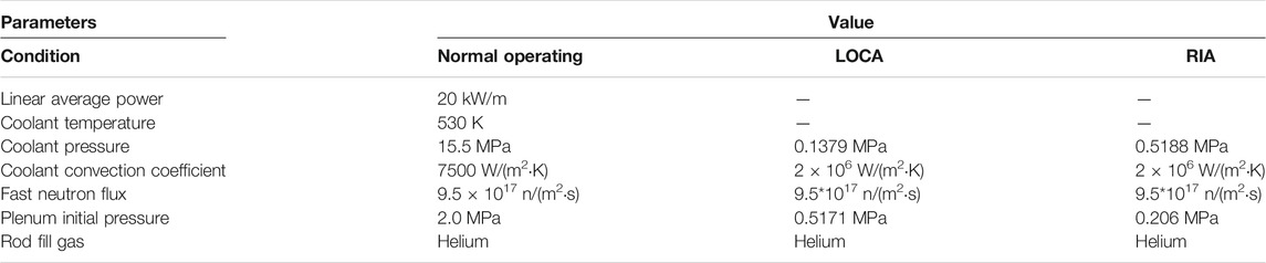
TABLE 2. Input parameters for normal operating and accident conditions.
Verification of LOCA
The linear power history and the cladding outer surface temperature evolution under the LOCA condition are shown in Figures 1, 2, respectively.
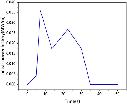
FIGURE 1. Linear power history of the UO2 fuel with Zircaloy cladding used to calculate the LOCA condition.
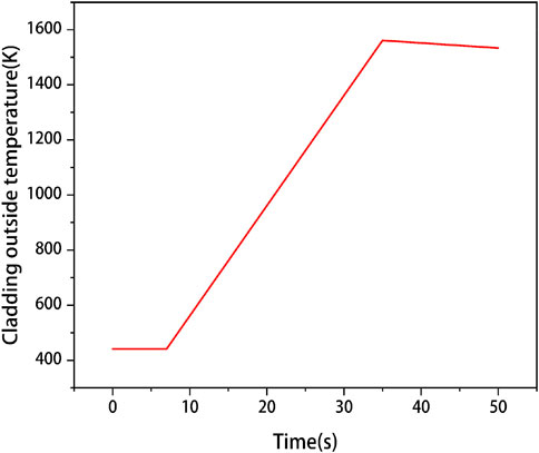
FIGURE 2. Cladding the outer surface temperature of the UO2 fuel with Zircaloy cladding used to calculate under the LOCA condition.
As depicted in Figure 3, the plenum pressure calculated by the CAMPUS and FRAPTRAN codes is found to remain at the initial value at the first few seconds, and then increase in a similar trend, because the fission gas is released to the gap. The cladding failure time calculated by the CAMPUS and FRAPTRAN codes is found to be nearly equal.
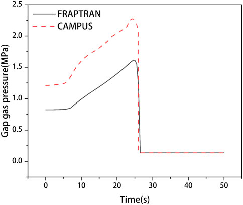
FIGURE 3. Plenum pressure evolutions of the UO2 fuel with Zircaloy cladding calculated by the FRAPTRAN and CAMPUS codes under the LOCA condition.
The gap size between fuel pellet and cladding is also compared; as depicted in Figure 4, a slight decrease of gap size can be observed from the results of both codes, which is caused by the thermal expansion and creep of fuel and cladding. Then, a rapid increase of gap size is found in the result from FRAPTRAN, and last, the gap size is found to remain unchanged, while from the results in the CAMPUS code, a delayed increase of gap size is found. Also, the calculated results from two codes are found to show the same evolution trend of the gap size.
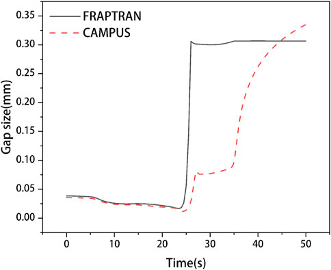
FIGURE 4. Gap size evolutions of the UO2 fuel with Zircaloy cladding calculated by the FRAPTRAN and CAMPUS codes under the LOCA condition.
In order to further verify our CAMPUS code, the results of cladding outer surface hoop strain calculated by the FRAPTRAN and CAMPUS codes are also compared, as depicted in Figure 5; the cladding outer surface hoop strain calculated from both codes is found to increase first. Then, similar to the evolution trend of plenum pressure, the cladding outer surface hoop strain calculated from two codes is found to have a dramatic increase and evolve to a similar hoop strain.
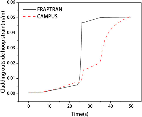
FIGURE 5. Cladding outer surface hoop strain evolutions of the UO2 fuel with Zircaloy cladding calculated by the FRAPTRAN and CAMPUS codes under the LOCA condition.
Verification of RIA
The linear power history and the cladding outside temperature evolution under the RIA condition are depicted in Figures 6, 7, respectively.
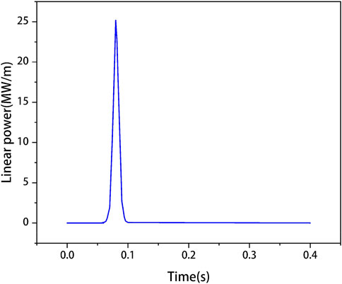
FIGURE 6. Linear power history of the UO2 fuel with Zircaloy cladding under the RIA condition.
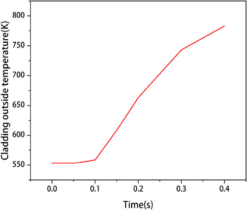
FIGURE 7. Cladding outer surface temperature of the UO2 fuel with Zircaloy cladding used to calculate the RIA condition.
As shown in Figure 8, the plenum pressure calculated by the CAMPUS and FRAPTRAN codes is found to remain at the initial value at the first few seconds. Then, due to a sudden increase of the fuel power, the temperature of the fuel, cladding, and gas in the gap are found to increase rapidly, resulting in an increase in the release rate of fission gas, which leads to a sudden increase of the gap pressure. Finally, the plenum pressure is found to decrease after the rapid increase due to the increase of gap size, which further results in the increase of plenum volume and the decrease of plenum pressure.
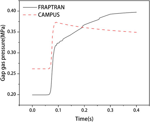
FIGURE 8. Plenum pressure evolutions of the UO2 fuel with Zircaloy cladding calculated by the FRAPTRAN and CAMPUS codes under the RIA condition.
As shown in Figure 9, the gap size evolutions between the fuel and cladding are also compared under RIA condition. At the initial moment, there is no heat generation in the fuel rod; therefore, the temperature of the fuel rod and cladding is found to remain unchanged, which means there is no thermal expansion and creep in the fuel and cladding. Then, the linear power of fuel is found to increase suddenly, resulting in the increase of fuel rod temperature, which leads to the thermal expansion and creep of the fuel pellet and cladding. Therefore, the gap size is found to decrease dramatically.
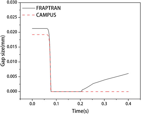
FIGURE 9. Gap size evolutions of the UO2 fuel with Zircaloy cladding calculated by the FRAPTRAN and CAMPUS codes under the RIA condition.
As depicted in Figure 10, similar to the same explanation as for gap size, no change is observed in the cladding outer surface hoop strain at the first few moments. Then, because of the thermal expansion and creep of the fuel pellet and cladding, cladding outer surface hoop strain is found to increase dramatically in a short time.
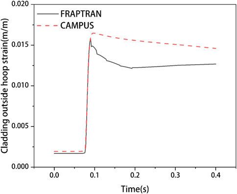
FIGURE 10. Cladding outer surface hoop strain evolution of the UO2 fuel with Zircaloy cladding calculated by the FRAPTRAN and CAMPUS codes under the RIA condition.
From the calculation results presented above, it can be observed that results calculated by the CAMPUS code are found to be consistent with the results calculated by the FRAPTRAN code, which verify the correctness of the CAMPUS code under accident conditions.
Results and Discussions
In this section, the fuel performance of the UO2 fuel with Zircaloy cladding, the Th0.923U0.077O2 fuel, and the Th0.923Pu0.077O2 fuel with Cr-coated SiC/SiC composite cladding under normal operating and accident conditions is presented and discussed.
Under Normal Operating Condition
The fuel performance of the UO2 fuel with Zircaloy cladding, the UO2 fuel with Cr-coated SiC/SiC composite cladding, the Th0.923U0.077O2 and Th0.923Pu0.077O2 fuels with Cr-coated SiC/SiC composite cladding is calculated under normal operating condition. The input parameters of the normal operating condition are summarized in Table 2. The linear power is kept at 20 kW/m after a steady rise for about 3 h, and then it operates stably for 3 years under this linear power. The temperature of the external coolant is set to be 530 K, and the pressure of the external coolant is set to be 15.5 MPa. The initial gap size is set to be 80 μm, and the initial plenum pressure is set to be 2 MPa for all types of fuels. Then, the results of fuel centerline temperature are depicted in Figure 11. First, the temperature of the Th0.923Pu0.077O2 fuel is found to be the highest before the fuel burnup reaches at 300 MWh/kgU. After this fuel burnup, the temperature of the UO2 fuel with Cr-coated SiC/SiC composite cladding is found to be the highest, and the temperature of the UO2 fuel with Zircaloy cladding is found to be the lowest, which is due to the fact that the thermal conductivity of the SiC/SiC composite cladding is lower than that of the Zircaloy cladding at the same temperature. Then, it is noticed that the centerline temperature of thorium-based fuels is found to be lower than that of the UO2 fuel with the same cladding, and the average temperature of the Th0.923U0.077O2 fuel is found to be about 100 K lower than that of the UO2 fuel with the same cladding, which is due to the higher thermal conductivity of thorium-based fuels than that of the UO2 fuel.
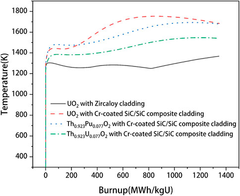
FIGURE 11. Fuel centerline temperature evolutions for the UO2 fuel with Zircaloy cladding, the Th0.923Pu0.077O2 fuel, and Th0.923U0.077O2 fuel with Cr-coated SiC/SiC composite cladding under the normal operating condition.
The plenum pressure is also calculated and compared. As shown in Figure 12, the UO2 fuel with the Cr-coated SiC/SiC composite cladding is found to have the highest plenum pressure, while the plenum pressure of the Th0.923U0.077O2 fuel with the same cladding is found to be the lowest. This is related to the factors such as fuel temperature and fission gas release fraction. As discussed in Figure 11, it is found that the UO2 fuel with Cr-coated SiC/SiC composite cladding has the highest temperature. Also, at the same fuel burnup, the fission gas release of the UO2 fuel with Cr-coated SiC/SiC composite cladding is found to be the earliest, and the release fraction is found to be much higher than that of the other three types of fuel and cladding combinations, as depicted in Figure 13. In short, the thorium-based fuel combined with Cr-coated SiC/SiC composite cladding can effectively reduce the plenum pressure.
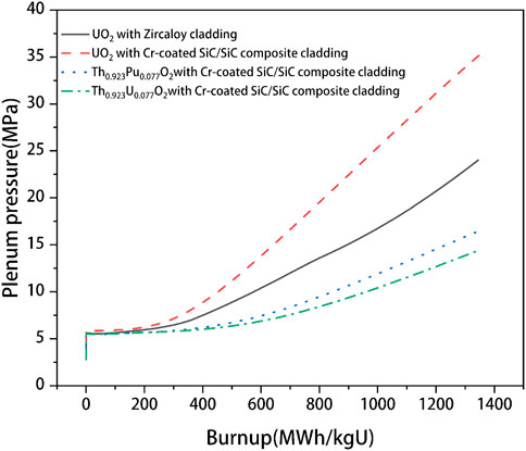
FIGURE 12. Plenum pressure evolutions for the UO2 fuel with Zircaloy cladding, the Th0.923Pu0.077O2 fuel, and Th0.923U0.077O2 fuel with Cr-coated SiC/SiC composite cladding under the normal operating condition.
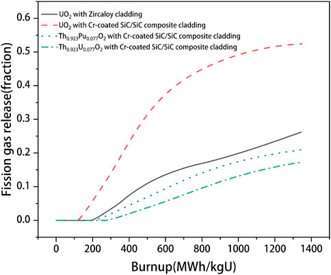
FIGURE 13. Fission gas release evolutions for UO2 fuel with Zircaloy cladding, the Th0.923Pu0.077O2 fuel, and Th0.923U0.077O2 fuel with Cr-coated SiC/SiC composite cladding under the normal operating condition.
As shown in Figure 14, the gap size evolutions are also calculated; it can be observed that the gap size of the UO2 fuel with Zircaloy cladding decreases the fastest, and the gap is found to close earliest. For the UO2 fuel combined with the Cr-coated SiC/SiC composite case, the gap size is found to decrease more slowly, and the PCMI time is found to be delayed. It is also found that for the thorium-based fuel combined with the Cr-coated SiC composite cladding case, the decrease rate of the gap size is further reduced, and the gap closure time is further delayed. This is because the SiC/SiC composite cladding has a higher elastic modulus and a lower thermal creep rate than that of Zircaloy cladding. The use of thorium-based fuels can reduce the overall temperature of the fuel, also reducing the thermal expansion of the fuel. This indicates that under normal operating condition, the use of thorium-based fuels with Cr-coated SiC composite cladding can delay the occurrence of pellet–cladding mechanical interaction (PCMI).
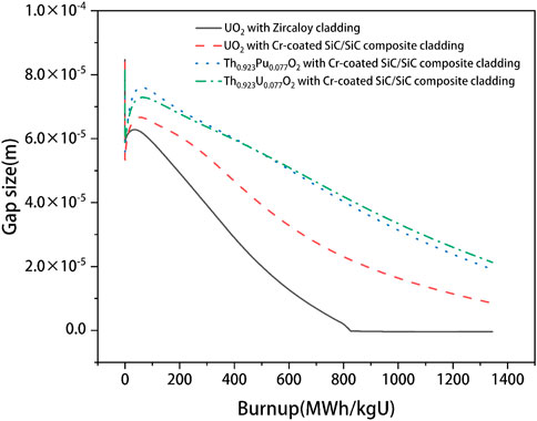
FIGURE 14. Gap size evolutions for the UO2 fuel with Zircaloy cladding, the Th0.923Pu0.077O2 fuel, and Th0.923U0.077O2 fuel with Cr-coated SiC/SiC composite cladding under the normal operating condition.
In summary, under the normal operating condition, compared with UO2 fuel with Zircaloy cladding, the combination of thorium-based fuels with Cr-coated SiC/SiC composite claddings is found to increase the fuel temperature, reduce the internal pressure of the fuel rod, delay the gap closure time, and improve fuel mechanical properties. Thorium-based fuels with Cr-coated SiC/SiC composite cladding are found to have better fuel performance under the normal operating condition. In addition, it should be noted that the performance of UO2 fuel with Cr-coated SiC/SiC cladding is found to be the worst among the combinations of fuels with claddings investigated under the normal operating condition, indicating that there is almost no fuel performance improvement to use the UO2 fuel with Cr-coated SiC/SiC cladding under the normal operating condition in LWRs; therefore, it will not be discussed under LOCA and RIA conditions.
Under LOCA Condition
In this part, the fuel performance of the UO2–Zircaloy, the Th0.923U0.077O2 fuel, and Th0.923Pu0.077O2 fuel combined with Cr-coated SiC/SiC composite cladding under the LOCA condition is discussed. The boundary conditions of the LOCA case are summarized in Table 2, and the power history is shown in Figure 1. It should be noted that in order to simplify the model, the drop of the external coolant level is not directly simulated, but external coolant temperature data calculated by the FRAPTRAN code under the corresponding accident condition are used as the Dirichlet boundary condition at the cladding outer surface. Moreover, the convective heat transfer coefficient between the cladding and the coolant is set to be a large value (listed in Table 2) to ensure the cladding outer surface temperature to be equal to that of the external coolant. Meanwhile, the same method is used to simulate the pressure change of the external coolant. Considering that the heat is transferred from the inside of the fuel to the outside, and the heat is conducted to the cladding and the external coolant through the gap gas, the initial temperature of the entire fuel is set to be consistent with the initial temperature of the outer surface of the cladding (namely, 441.5 K). Similarly, the initial value of the plenum pressure calculated by the FRAPTRAN code is adopted as the initial value of the plenum pressure for the LOCA condition in this work. The failure time of the cladding, the evolution of the plenum pressure, and the degree of deformation of the cladding are the key parameters to evaluate the accident tolerance performance of the fuel under the LOCA condition.
The centerline temperature of the three types of fuel cases is calculated and depicted in Figure 15. First, an early increase of temperature is observed in the UO2 fuel with Zircaloy cladding, while the Th0.923Pu0.077O2 fuel is found to have the latest increase of temperature. Then, the temperature increase rate of the UO2 fuel is consistent with that of the Th0.923U0.077O2 fuel, and the Th0.923Pu0.077O2 fuel is found to have the smallest increase rate of temperature. This is because in the temperature range shown in Figure 15, the PuO2 fuel is found to have a higher heat capacity than the UO2 fuel and ThO2 fuel. Finally, the centerline temperature of Th0.923Pu0.077O2 fuel is found to be the lowest compared to that of the other two types of fuels.
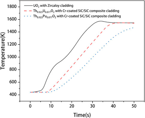
FIGURE 15. Fuel centerline temperature evolutions for the UO2 fuel with Zircaloy cladding, the Th0.923Pu0.077O2 fuel, and Th0.923U0.077O2 fuel with Cr-coated SiC/SiC composite cladding under LOCA conditions.
As shown in Figure 16, the failure time of two types of claddings is evaluated and compared. In order to facilitate the observation and comparison of the failure time of the cladding, the hoop strain on the outer surface of the SiC/SiC composite cladding is set to be zero after it exceeds 0.6%. Similarly, the creep rate of the Zircaloy cladding outer surface is set to be zero, when it exceeds 0.0278(1/s), as shown in Eq. 10. It can be observed from Figure 16 that the cladding failure time of the UO2 fuel and the Th0.923U0.077O2 fuel is basically the same, while the cladding failure time of the Th0.923Pu0.077O2 fuel is found to have a significant delay. This is due to the higher heat capacity of the Th0.923Pu0.077O2 fuel, which results in the overall average temperature of the Th0.923Pu0.077O2 fuel to be lower than the overall average temperature of the Th0.923U0.077O2 fuel, as depicted in Figure 15, which further causes the gap width of the Th0.923Pu0.077O2 fuel and the Cr-coated SiC/SiC composite cladding to be larger than that of the UO2 fuel and Zircaloy cladding before the cladding failure time, as shown in Figure 17. Thus, the cladding average temperature of SiC/SiC composite cladding is found to be slightly lower than that of Zircaloy cladding, as depicted in Figure 18. Young’s modulus of the SiC/SiC composite cladding is found to be higher than that of the Zircaloy cladding. Therefore, the cladding failure time of the Th0.923Pu0.077O2 fuel is found to have a significant delay. As shown in Figure 19, compared to the SiC/SiC composite cladding, the Zircaloy cladding outer surface is found to have a higher hoop strain, which is also due to the higher Young’s modulus of SiC/SiC composite. These results indicate that under the LOCA condition, the Cr-coated SiC/SiC composite cladding is found to have better accident tolerance than the Zircaloy cladding.
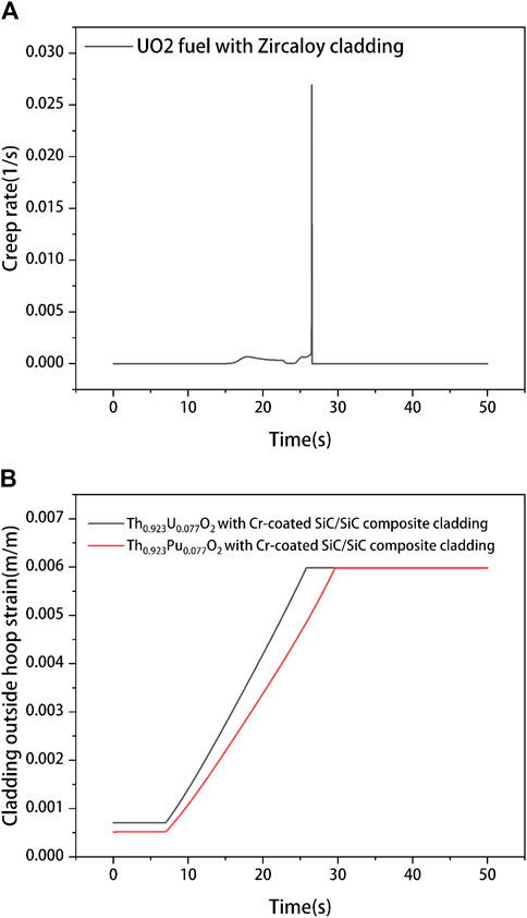
FIGURE 16. Cladding failure time for (A) UO2 fuel with Zircaloy cladding, (B) the Th0.923Pu0.077O2 fuel, and Th0.923U0.077O2 fuel with Cr-coated SiC/SiC composite cladding under the LOCA condition.
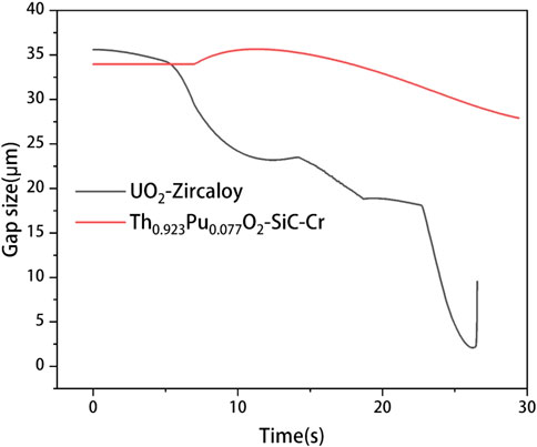
FIGURE 17. Gap width evolution of UO2 fuel with Zircaloy cladding and Th0.923Pu0.077O2 fuel with Cr-coated SiC/SiC composite cladding.

FIGURE 18. Average temperature of Zircaloy cladding and Cr-coated SiC/SiC composite cladding.
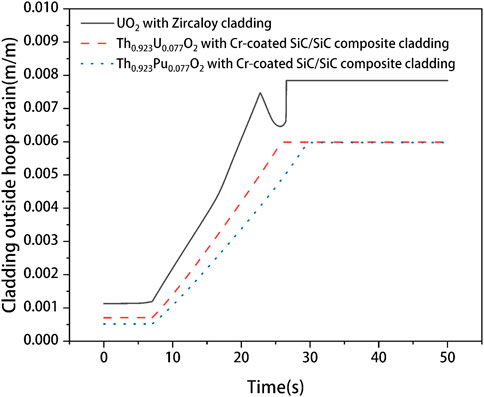
FIGURE 19. Hoop strain evolutions for the cladding of the UO2 fuel, the cladding of the Th0.923Pu0.077O2 fuel, and Th0.923U0.077O2 fuel under LOCA condition, respectively.
As it is assumed that the internal plenum pressure is consistent with the external coolant pressure after the cladding failed, the pressure data at the corresponding time are set to be consistent with the external coolant pressure when the cladding failure occurs. As shown in Figure 20, the plenum pressure of the UO2 fuel rod is found to increase at the earliest and has the fastest increase rate, while the plenum pressure increase rate of the Th0.923Pu0.077O2 fuel rod is found to be the smallest. The pressure of the Th0.923Pu0.077O2 fuel rod is found to be lower than that of the other two types of fuel rods. This is because the overall temperature of the Th0.923Pu0.077O2 fuel rod is lower than that of the other two types of fuel rods. So on the one hand, it causes lowering of the plenum pressure under the same volume and smaller gas volume of the fuel rod. On the other hand, it also reduces the thermal expansion of the fuel and the cladding; therefore, the free volume inside the fuel rod increases.
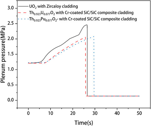
FIGURE 20. Plenum pressure evolutions for the UO2 fuel with Zircaloy cladding, the Th0.923Pu0.077O2 fuel, and Th0.923U0.077O2 fuel with Cr-coated SiC/SiC composite cladding under the LOCA condition, respectively.
In all, under the LOCA condition, the use of thorium-based fuels, especially the Th0.923Pu0.077O2 fuel with Cr-coated SiC/SiC composite cladding, is found to effectively reduce the temperature of the fuel centerline and delay the failure time of the cladding. The use of the Th0.923Pu0.077O2 fuel with Cr-coated SiC/SiC composite cladding fuel is also found to reduce the strain on the cladding outer surface and further reduce the plenum pressure.
Under the RIA Condition
The fuel performance under the RIA condition is calculated and discussed in this section. The calculation parameters under the RIA condition are also summarized in Table 2, and the linear power history is shown in Figure 3.
As shown in Figure 21A, the fuel centerline temperature of different fuels is calculated. In the beginning, the centerline temperature of the three types of fuels is found to remain unchanged. Then, the centerline temperature of the three types of fuels is found to increase at about 0.06 s and remain unchanged after about 0.1 s. However, different from the normal operating and LOCA conditions, the fuel centerline temperature of Th0.923U0.077O2 fuel and Th0.923Pu0.077O2 fuel is found to be about 2,400 K, and the temperature of Th0.923U0.077O2 fuel is found to be slightly lower than that of the Th0.923Pu0.077O2 fuel but to be much higher than that of the UO2 fuel. This is due to the thermal conductivity of SiC/SiC composite cladding being lower than Zircaloy cladding after about 0.1 s, as depicted in Figure 21B, which results in the condition that heat generated by thorium-based fuels cannot be conducted as fast as that generated by the UO2 fuel and further causes the temperature of thorium-based fuels to be higher than that of the UO2 fuel.
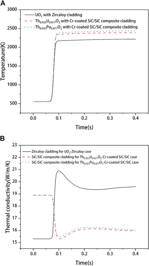
FIGURE 21. (A) Fuel centerline temperature evolutions for the UO2 fuel with Zircaloy cladding, the Th0.923Pu0.077O2 fuel, and Th0.923U0.077O2 fuel with Cr-coated SiC/SiC composite cladding under the RIA condition. (B) Thermal conductivity evolutions of Zircaloy cladding for UO2–Zircaloy case, SiC/SiC composite for Th0.923U0.077O2–Cr-coated SiC/SiC and Th0.923Pu0.077O2–Cr-coated SiC/SiC cases.
As shown in Figure 22, the cladding outer surface strain is further discussed. It should be noted that in this work, due to the short calculation time (0.4 s) for the RIA condition, the complete brittle failure of the SiC composite is not considered. At the initial moment, the strain of the Zircaloy cladding is found to be higher than that of the Cr-coated SiC/SiC composite cladding. This is because the thermal expansion properties and creep properties of the Zircaloy cladding are different from those of SiC/SiC composite cladding. Then, as the linear power suddenly increases, the hoop strain of the cladding is found to increase dramatically. It can be observed that the Zircaloy cladding outer surface strain is found to be much higher than that of the Cr-coated SiC/SiC composite cladding, which is due to the better mechanical properties of the Cr-coated SiC/SiC composite cladding. The larger hoop strain of the Zircaloy cladding will increase the stress in the cladding. In short, under the RIA condition, the use of Cr-coated SiC/SiC composite cladding is beneficial to reduce the deformation of the cladding and improve the mechanical performance of the cladding.
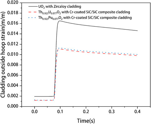
FIGURE 22. Hoop strain evolutions for the cladding of the UO2 fuel, the cladding of the Th0.923Pu0.077O2 fuel, and Th0.923U0.077O2 fuel under the RIA condition.
In summary, under the RIA condition, as the accident occurs at about 0.1 s, it causes the heat accumulation and rapid increase of fuel temperature in a short time, and then the thermal conductivity of the SiC/SiC composite cladding becomes lower than that of the Zircaloy cladding; therefore, the use of the Th0.923U0.077O2 and Th0.923Pu0.077O2 fuels with Cr-coated SiC composite cladding is found to increase the fuel centerline temperature. The use of the new fuel–cladding combinations is found to have no significant effect on delaying the gap closure time and improving PCMI. In addition, the use of the new fuel–cladding combinations is found to effectively reduce the hoop strain on the outer surface of the cladding, thereby reducing the internal plenum pressure of the fuel rod.
Conclusion
In summary, the fuel performance of the UO2 fuel with Zircaloy cladding and thorium-based fuels with Cr-coated SiC/SiC composite cladding under LWR normal operating, LOCA, and RIA conditions is studied in this work. Based on the discussions presented above, the conclusions are summarized as follows:
1. Under the normal operating condition, compared with the UO2–Zircaloy fuel, the use of the thorium-based fuels (including Th0.923U0.077O2 fuel and Th0.923Pu0.077O2 fuel) with Cr-coated SiC/SiC composite cladding is found to be able to reduce the fission gas release at the same burnup, thereby reducing the internal pressure of the fuel rod. At the same time, the use of thorium-based fuels with Cr-coated SiC/SiC composite cladding is found to effectively delay the gap closure time. However, the use of these two types of fuels is found to increase the fuel centerline temperature. Compared with the other three types of fuels, the performance of the UO2 fuel with Cr-coated SiC/SiC composite cladding is found to be the worst, indicating there is almost no advantage to use the UO2 fuel with Cr-coated SiC/SiC cladding under the normal operating condition in LWRs; therefore, the performance of this type of fuel under LOCA and RIA conditions is not discussed.
2. Under the LOCA condition, it is observed that compared with the UO2–Zircaloy fuel, the Th0.923U0.077O2 fuel and Th0.923Pu0.077O2 fuel with Cr-coated SiC/SiC composite cladding are found to delay the increase of the fuel centerline temperature, and the fuel centerline temperature of Th0.923Pu0.077O2 fuel is found to be the lowest. At the same time, the Th0.923Pu0.077O2 fuel with Cr-coated SiC/SiC composite cladding is found to delay the failure of the cladding, which is the main conclusion of this work. Moreover, it is also found to reduce the cladding outer surface hoop strain and the plenum pressure of the fuel rod. Therefore, under the LOCA condition, the Th0.923Pu0.077O2 fuel with Cr-coated SiC/SiC composite cladding is considered to have better accident tolerance.
3. Under the RIA condition, the use of the Th0.923U0.077O2 and Th0.923Pu0.077O2 fuels with Cr-coated SiC/SiC composite cladding is found to increase the fuel centerline temperature. It is also observed that the thorium-based fuels with Cr-coated SiC/SiC composite cladding have no significant influence on the gap closure time. However, it is found that the Th0.923U0.077O2 and Th0.923Pu0.077O2 fuels with Cr-coated SiC/SiC composite cladding can effectively reduce the plenum pressure in the fuel rod and reduce the hoop strain of the cladding.
The results of this study show that under both normal operating and LOCA conditions, the Th0.923U0.077O2 fuel and Th0.923Pu0.077O2 fuel with Cr-coated SiC/SiC composite cladding are found to reduce the fuel centerline temperature and delay the PCMI time. Meanwhile, the Th0.923U0.077O2 and Th0.923Pu0.077O2 fuels with Cr-coated SiC/SiC composite cladding are found to delay the failure of the cladding. While under the RIA condition, the use of the Th0.923U0.077O2 and Th0.923Pu0.077O2 fuels is found to reduce the plenum pressure of the fuel rod but increase the fuel centerline temperature.
Data Availability Statement
The raw data supporting the conclusion of this article will be made available by the authors, without undue reservation.
Author Contributions
SL: data curation, investigation, writing—original draft, validation, and writing—review and editing. RL: conceptualization, methodology, supervision, and writing—review and editing. CQ: conceptualization, methodology, and writing—review and editing. WZ: methodology and writing—review and editing.
Funding
The financial supports from the National Natural Science Foundation of China (Grant no. 11805070), the Natural Science Foundation of Guangdong Province (Grant no. 2020A1515010648), and the Fundamental Research Funds for the Central Universities (Grant no. 2019MS016) are highly appreciated.
Conflict of Interest
The authors declare that the research was conducted in the absence of any commercial or financial relationships that could be construed as a potential conflict of interest.
References
Ade, B., Worrall, A., Powers, J., and Bowman, S. (2016). Analysis of Key Safety Metrics of Thorium Utilization in LWRs. Nucl. Technology 194 (2), 162–177. doi:10.13182/nt15-100
Armstrong, P. E., and Brown, H. L. (1964). Dynamic Young's Modulus Measurements above 1000 C on Some Pure Polycrystalline Metals and Commercial Graphites. Trans. Aime 230. LADC-6100. Available at https://www.osti.gov/biblio/4018502.
Ben-Belgacem, M., Richet, V., Terrani, K. A., Katoh, Y., and Snead, L. L. (2014). Thermo-mechanical Analysis of LWR SiC/SiC Composite Cladding. J. Nucl. Mater. 447 (1-3), 125–142. doi:10.1016/j.jnucmat.2014.01.006
Carter, C. H., Davis, R. F., and Bentley, J. (1984). Kinetics and Mechanisms of High-Temperature Creep in Silicon Carbide: II, Chemically Vapor Deposited. J. Am. Ceram. Soc. 67 (11), 732–740. doi:10.1111/j.1151-2916.1984.tb19510.x
Deck, C. P., Jacobsen, G. M., Sheeder, J., Gutierrez, O., Zhang, J., Stone, J., et al. (2015). Characterization of SiC-SiC Composites for Accident Tolerant Fuel Cladding. J. Nucl. Mater. 466, 667–681. doi:10.1016/j.jnucmat.2015.08.020
Di Marcello, V., Schubert, A., van de Laar, J., and van Uffelen, P. (2014). The TRANSURANUS Mechanical Model for Large Strain Analysis. Nucl. Eng. Des. 276, 19–29. doi:10.1016/j.nucengdes.2014.04.041
Düz, M. (2021). Neutronic Calculations for Certain Americium Mixed Fuels and Clads in a Boiling Water Reactor. Front. Energ. Res. 9, 38. doi:10.3389/fenrg.2021.639416
Eck, R., Martinz, H. P., Sakaki, T., and Kato, M. (1989). Powder Metallurgical Chromium. Mater. Sci. Eng. A 120-121, 307–312. doi:10.1016/0921-5093(89)90755-7
Frazer, D., Abad, M. D., Krumwiede, D., Back, C. A., Khalifa, H. E., Deck, C. P., et al. (2015). Localized Mechanical Property Assessment of SiC/SiC Composite Materials Part A Applied Science and Manufacturing.
Galahom, A. A. (2017). Minimization of the Fission Product Waste by Using Thorium Based Fuel Instead of Uranium Dioxide. Nucl. Eng. Des. 314, 165–172. doi:10.1016/j.nucengdes.2017.01.024
Geelhood, K. J., and Luscher, W. G. (2014). FRAPTRAN1.5: Integral Assessment. PNNL 2. Rev. 1. Available at https://www.nrc.gov/reading-rm/doc-collections/nuregs/contract/cr7023/v2/r1/index.html.
Gulbransen, E. A., and Jansson, S. A. (1972). The High-Temperature Oxidation, Reduction, and Volatilization Reactions of Silicon and Silicon Carbide. Oxid Met. 4 (3), 181–201. doi:10.1007/bf00613092
Hales, J. D., Williamson, R. L., Novascone, S. R., Pastore, G., Spencer, B. W., Stafford, D. S., et al. (2016). BISON Theory Manual the Equations behind Nuclear Fuel Analysis (No. INL/EXT-13-29930). Idaho Falls, ID: Idaho National Lab. doi:10.2172/1374503
Holzwarth, U., and Stamm, H. (2002). Mechanical and Thermomechanical Properties of Commercially Pure Chromium and Chromium Alloys. J. Nucl. Mater. 300 (2-3), 161–177. doi:10.1016/s0022-3115(01)00745-0
Kabach, O., Chetaine, A., Benchrif, A., and Amsil, H. (2020). Neutronic Investigation of the Thorium-Based Mixed-Oxide as an Alternative Fuel in the TRIGA Mark-II Research Reactor - Part I: A Beginning of Life Calculations. Ann. Nucl. Energ. 140, 107075. doi:10.1016/j.anucene.2019.107075
Katoh, Y., Snead, L. L., Cheng, T., Shih, C., Lewis, W. D., Koyanagi, T., et al. (2014a). Radiation-tolerant Joining Technologies for Silicon Carbide Ceramics and Composites. J. Nucl. Mater. 448 (1-3), 497–511. doi:10.1016/j.jnucmat.2013.10.002
Katoh, Y., Snead, L. L., Henager, C. H., Nozawa, T., Hinoki, T., Iveković, A., et al. (2014b). Current Status and Recent Research Achievements in SiC/SiC Composites. J. Nucl. Mater. 455 (1-3), 387–397. doi:10.1016/j.jnucmat.2014.06.003
Kohyama, A., and Hirotatsu, K. (2013). SiC/SiC Composite Materials for Nuclear Applications. Nucl. Saf. Simul. 4, 72–79. Available at https://scholar.google.com/scholar?q=SiCSiC%20composite%20materials%20for%20nuclear%20application.
Korkut, T., Kara, A., and Korkut, H. (2016). Effect of Ultra High Temperature Ceramics as Fuel Cladding Materials on the Nuclear Reactor Performance by SERPENT Monte Carlo Code. Kerntechnik 81 (6), 599–608. doi:10.3139/124.110580
Lee, Y., Koyanagi, T., Pint, B. A., and Kato, Y. (2019). High Temperature Steam Oxidation of Cr-Coated SiCf/SiC Composite for LWR Cladding Applications. Oak Ridge, TN: Oak Ridge National Lab.(ORNL).
Liu, R., Cai, J., and Zhou, W. (2020). Multiphysics Modeling of Thorium-Based Fuel Performance with a Two-Layer SiC Cladding in a Light Water Reactor. Ann. Nucl. Energ. 136, 107036. doi:10.1016/j.anucene.2019.107036
Liu, R., Prudil, A., Zhou, W., and Chan, P. K. (2016). Multiphysics Coupled Modeling of Light Water Reactor Fuel Performance. Prog. Nucl. Energ. 91, 38–48. doi:10.1016/j.pnucene.2016.03.030
Long, Y. (2002). Modeling the Performance of High Burnup Thoria and Urania Pwr Fuel. Cambridge, United Kingdom: Doctoral dissertation, Massachusetts Institute of Technology.
Massalski, T. B., Okamoto, H., Subramanian, P. R., and Kacprzak, L. (1991). Binary Alloy Phase Diagrams. Materials Park, OH: ASM International. 1990.
Mieloszyk, A. J. (2015). Assessing Thermo-Mechanical Performance of ThO₂ and SiC Clad Light Water Reactor Fuel Rods with a Modular Simulation Tool. Cambridge, United Kingdom: Doctoral dissertation, Massachusetts Institute of Technology.
Singh, G., Terrani, K., and Katoh, Y. (2018). Thermo-mechanical Assessment of Full SiC/SiC Composite Cladding for LWR Applications with Sensitivity Analysis. J. Nucl. Mater. 499, 126–143. doi:10.1016/j.jnucmat.2017.11.004
Snead, L. L., Nozawa, T., Katoh, Y., Byun, T. S., Kondo, S., and Petti, D. A. (2007). Handbook of SiC Properties for Fuel Performance Modeling. J. Nucl. Mater. 371 (1-3), 329–377. doi:10.1016/j.jnucmat.2007.05.016
Sokolov, F., Fukuda, K., and Nawada, H. P. (2005). Thorium Fuel Cycle-Potential Benefits and Challenges. IAEA TECDOC, 1450.
Stone, J. G., Schleicher, R., Deck, C. P., Jacobsen, G. M., Khalifa, H. E., and Back, C. A. (2015). Stress Analysis and Probabilistic Assessment of Multi-Layer SiC-Based Accident Tolerant Nuclear Fuel Cladding. J. Nucl. Mater. 466, 682–697. doi:10.1016/j.jnucmat.2015.08.001
Tucker, L. P., and Usman, S. (2018). Thorium-based Mixed Oxide Fuel in a Pressurized Water Reactor: A Burnup Analysis with MCNP. Ann. Nucl. Energ. 111, 163–175. doi:10.1016/j.anucene.2017.08.057
Ünak, T. (2000). What Is the Potential Use of Thorium in the Future Energy Production Technology?. Prog. Nucl. Energ. 37 (1-4), 137–144. doi:10.1016/s0149-1970(00)00038-x
Wagih, M., Spencer, B., Hales, J., and Shirvan, K. (2018). Fuel Performance of Chromium-Coated Zirconium alloy and Silicon Carbide Accident Tolerant Fuel Claddings. Ann. Nucl. Energ. 120, 304–318. doi:10.1016/j.anucene.2018.06.001
Weaver, K. D., and Herring, J. S. (2002). Performance of Thorium-Based Mixed Oxide Fuels for the Consumption of Plutonium and Minor Actinides in Current and Advanced Reactors (No. INEEL/CON-01-01427). Idaho Falls, ID: Idaho National Laboratory (INL).
Keywords: thorium-based fuel, CAMPUS, fuel performance, Cr-coated SiC/SiC composite cladding, accident condition
Citation: Liu S, Liu R, Qiu C and Zhou W (2021) Multiphysics Modeling of Thorium-Based Fuel Performance With Cr-Coated SiC/SiC Composite Under Normal and Accident Conditions. Front. Energy Res. 9:677606. doi: 10.3389/fenrg.2021.677606
Received: 08 March 2021; Accepted: 31 May 2021;
Published: 23 June 2021.
Edited by:
Hitesh Bindra, Kansas State University, United StatesReviewed by:
Ayhan Kara, Giresun University, TurkeyJinfeng Li, Imperial College London, United Kingdom
Copyright © 2021 Liu, Liu, Qiu and Zhou. This is an open-access article distributed under the terms of the Creative Commons Attribution License (CC BY). The use, distribution or reproduction in other forums is permitted, provided the original author(s) and the copyright owner(s) are credited and that the original publication in this journal is cited, in accordance with accepted academic practice. No use, distribution or reproduction is permitted which does not comply with these terms.
*Correspondence: Rong Liu, cmxpdTI5MDE0N0Bob3RtYWlsLmNvbQ==