 Fawen Zhu
 Lele Zheng
 Quan-Yao Ren
 Ti Yue
 Hua Pang
- Science and Technology on Reactor System Design Technology Laboratory, Nuclear Power Institute of China, Chengdu, China
As one of the Generation IV nuclear reactors, the SCWR (supercritical water-cooled reactor) has high economy and safety margin, good mechanical properties for its high thermal efficiency, and simplified structure design. As the key component of nuclear reactor, the fuel assembly has always been the main issue for the design of the SCWR. The design of the fuel assembly for CSR1000 proposed by the Nuclear Power Institute of China (NPIC) has been optimized and presented in this study, which is composed of four subassemblies welded by four filler strips and guide thimbles arranged close together in the cross-shaped passage. Aiming at improving the hydraulic buffer performance of the cruciform control rod, the scram time and terminal velocity of control rod assembly were calculated to assess the scram performance based on the computational fluid dynamics and dynamic mesh method, and the mechanical property and neutronic performance of assemblies were also investigated. It has been demonstrated that the optimized fuel assembly had good feasibility and performance, which was a promising design for CSR1000.
Introduction
The supercritical water-cooled reactor (SCWR) is one of the most promising reactors for Generation IV nuclear reactors due to its higher thermal efficiency and more simplified structure than the state-of-the-art LWRs (light water reactors). In order to achieve a better thermal efficiency, the coolant inlet temperature was 280°C and the outlet temperature was over 500°C in the reactor core, which caused a high heat-up of the coolant within the core by more than 200°C (Squarer et al., 2003). Thus, the fuel assembly had to withstand the high temperature, high temperature difference, and high neutron irradiation in normal operating conditions, making the design of the fuel assembly more complex and difficult.
Although many challenges exist, many countries and research organizations have proposed their fuel assembly concepts since 1990. A two-pass core composed of 121 square fuel assemblies with a single row of fuel rods between water rods was adopted by the Japanese Super LWR (Yamaji et al., 2005), a three-pass core with a square fuel assembly cluster consisting of nine subassemblies was proposed by the European HPLWR (Fischer et al., 2009), and a one-pass core with square assemblies and water rods was developed by the American SCWR (Buongiorno and MacDonald, 2003). In Korea, the assemblies were square-type with a cruciform type U/Zr solid moderator to avoid complicated water flow paths (Bae et al., 2007), while in Canada, the fuel assembly of CANDU-SCWR continued the pressure tube (PT)/Calandria tube (CT) design from CANDU, and the moderator adopted the design of the heavy-water reactor (Leung, 2015). So far, most concept designs of the thermal SCWR fuel assembly were square-type, with water rods as an extra moderator. The high enthalpy rose in the core enabled the use of two- and three-pass cores, which reduced the maximum cladding temperature (Reiss et al., 2010). Moreover, many studies devoted to the heat transfer performance of supercritical fluid. Xiong et al. (Xiong and Cheng, 2014; Xiong et al., 2015) proposed a four-equation model to predict the mixed convective heat transfer in supercritical pressure fluid and assessed the performance of RANS models in predicting supercritical pressure heat transfer in a 2 × 2 rod bundle. Castro et al. (2020) performed coupled calculations with the CFD code CFX-19.0 and the Monte Carlo neutronic code MCNP6 to analyze the heat transfer in supercritical water flowing through the typical fuel assembly of the high-performance light water reactor (HPLWR).
In China, a thermal spectrum SCWR concept called CSR1000 was proposed by the Nuclear Power Institute of China (NPIC) with a two-pass core arrangement, which increased the core heating length and decreased the temperature difference in the axial direction effectively (Xia et al., 2013). The preliminary safety evaluation (Wu et al., 2014) and LOCA analysis (Chen et al., 2017) for CSR1000 were also conducted. Considering the two-pass core structure of CSR1000 and the separation of moderator water and coolant water, the new design of the 2 × 2 fuel assembly cluster consisting of four subassemblies was developed (Zhu et al., 2013). Furthermore, a kind of configuration design of the fuel assembly with SiC as the cladding material was proposed (Feng and Zhu, 2016). Yang et al. (2012) presented an optimized design of the fuel assembly for the fast zone of a mixed-spectrum supercritical water-cooled reactor (SCWR-M), which had a multilayer structure and was divided into several seed and blanket layers.
However, there still are some issues to be addressed, especially the large drop load of the cruciform control rod on the fuel assembly. In the present study, the design of the fuel assembly for CSR1000 had been optimized, whose scram performance, mechanical properties, and neutron moderation were analyzed and discussed in detail.
The Design Optimization
The Previous Plate-Type Design
CSR1000 was a pressure-vessel SCWR concept with 157 fuel assemblies, and the active core was 4.2 m. In the previous design as shown in Figure 1, each fuel assembly consisted of four subassemblies, while each subassembly contained 56 fuel rods and one square moderator box located in the center. In order to strengthen the lateral support and connect subassemblies into a cluster, two grids with the height of 30 mm were designed. The cruciform control rod with the thickness of 8 mm was adopted, which served as the cross channel for the intervention of the cruciform control rod from the top of the assembly (Feng and Zhu, 2016). It should be noted that it contained 60 control rods with the absorber diameter of 5.6 mm.
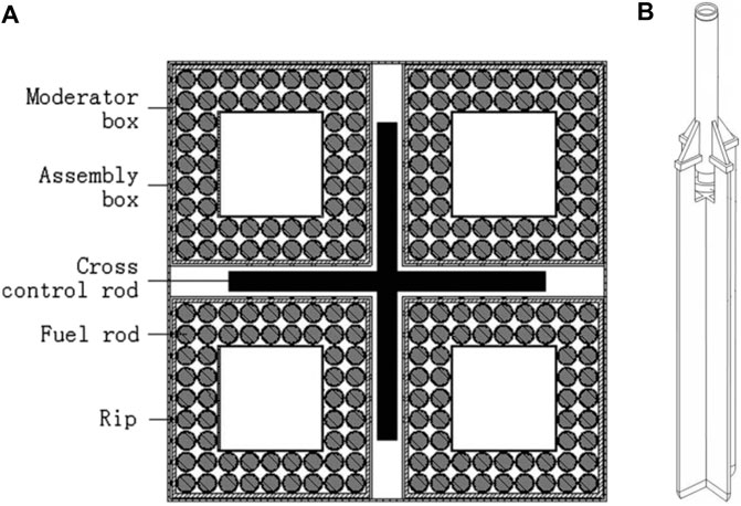
FIGURE 1. Previous fuel assembly and the cruciform control rod. (A) Cross-sectional design and (B) the cruciform control rod.
The numerical simulation was conducted on the dropping and buffering behavior of the cruciform control rod by Xiao et al. (2017), and it was demonstrated that the whole drop time of the cruciform control rod was about 1.018 s, with the drop distance of 4.1 m. However, at the end of the whole drop distance, the velocity of control rod was up to 7.64 m/s, which would result in the too large impact load on the fuel assembly to guarantee the structure integrity of the fuel assembly. The large impact load was attributed to the lack of hydraulic buffer effect when the cruciform control rod was inserted into the fuel assembly, which was a key design for the rod cluster control assemblies (RCCAs) in the pressurized water reactor (PWR). Moreover, considering that the irradiation deformation of the cruciform control rod was much larger than that of the RCCA in the PWR, the gap between the cruciform control rod and the cross channel of the fuel assembly must be set as a reasonable value.
The Optimized Rod-Type Design
In order to strengthen the hydraulic buffer property of the cruciform control rod, an optimized design of the fuel assembly was proposed, as shown in Figure 2. The fuel assembly comprised four subassemblies, which were welded together by four filler strips instead of grids along the axial height, so as to minimize thermal deflection of the fuel assembly. The number and dimension of fuel rods among the fuel assembly were the same as those of the previous design. The radial fixed position of the fuel rod was rip wrapped instead of wire wrapped, which can reduce the flow-induced vibration due to the high flow velocity of the coolant. In addition, in order to insulate the heat transfer of inside and outside of moderator box, the thickness of the moderator box was increased to 2 mm, which was the same as that of the assembly box, including the wall thickness of 0.5 mm at both sides and ZrO2 filling in the middle with the thickness of 1 mm. The comparison of main parameters between the previous plate-type and optimized rod-type fuel assemblies for CSR1000 is listed in Table 1.
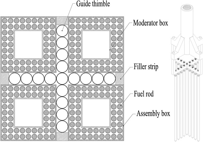
FIGURE 2. Optimized fuel assembly and the cruciform control rod. (A) Cross-sectional design and (B) the cruciform control rod.

TABLE 1. Comparison between the previous design and optimized structure.
There were 17 guide thimbles arranged close together in the cross-shaped passage, which was surrounded by the walls of four subassembly boxes. Aiming at reducing the impact load on the fuel assembly, the guide thimbles were designed as shown in Figure 3, which consisted of the upper buffer with the inner diameter of 19 mm, the lower buffer with the inner diameter of 18 mm, and the drain hole with the diameter of 3 mm. When the cruciform control rod assembly is inserted into the guide thimbles, the coolant would be ejected out from the drain holes and top gaps between control rods and guide thimbles, which would provide enough and increasing hydraulic buffering force.
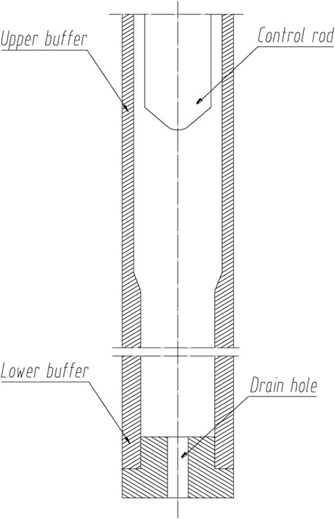
FIGURE 3. Scheme of guide thimble.
The optimized design of the cruciform control rod is also given in Figure 2B. Different from the conventional cruciform control rod design like that in Figure 1, the optimized design adopted the cylindrical rods hanging on the cross-shaped beam, which matched the structure of guide thimbles in the optimized fuel assembly in Figure 2A. When the optimized cruciform control rod is inserted into the guide thimbles of the fuel assembly, the small annular gap between the control rod and guide thimble increased the hydraulic buffer effect greatly, especially in the lower buffer section. Therefore, the impact force on the fuel assembly might be decreased significantly. Besides, the water gap between the guide thimble and cross-shaped passage could improve the power distribution characteristics and decrease the power peak factor of the fuel assembly in the reactor core.
The Design Analysis
Scram Analysis
In the SCWR, the control rod drop behavior is the key issues for the reactor safety and the integrity of the fuel assembly. For the optimized cruciform control rod, each control rod corresponded to every single guide thimbles of the fuel assembly. It was expected that the control rods dropped quickly through the upper buffer and dropped slowly in the lower buffer, so as to control the reactivity of the reactor and decrease the impact force on the fuel assembly separately.
Computational Fluid Dynamic Numerical Method
In order to evaluate the dropping time and buffering behaviors of the optimized fuel assembly, the dynamic mesh method in computational fluid dynamics (CFD) was utilized to conduct the numerical study on the dropping process of the optimized control rod. Since the whole system was symmetric, the quarter geometrical structure and periodic boundary conditions were used, and all of the boundary conditions for solid in this simulation were set as wall. The gravitational acceleration was set as 0, 0, and −9.81 m/s2 because the control rod was designed to drop along the z-direction. By neglecting that the fluid in the guide thimble was isothermal, only the mass and momentum conservation equations were adopted to analyze the whole process. The RNG k-e turbulence model was recognized to be able to obtain high calculation accuracy in engineering applications; thus, it was applied in the numerical simulation. The mass of the control rod was set as 90 kg, and the physical properties of water are listed in Table 2. It should be noted that the water temperature was defined as the average value between the inlet and the outlet temperature.
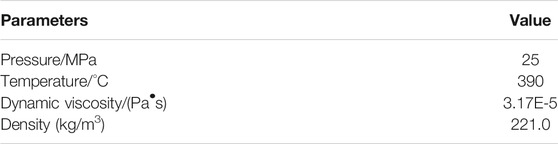
TABLE 2. Physical properties of water.
Aiming at simulating the dropping process of control rod, six degree of freedom (6 DOF, one of the dynamic mesh methods) was used by changing the mesh size to simulate the volume change of fluid domain. Moreover, in order to avoid the appearance of negative volume mesh, structured grid was adopted. And, the layering method was employed to update the mesh, and the height-based layering method with the split factor of 0.4 and collapse factor of 0.2 was used. The total number of grids was approximately 18 million, and the minimum orthogonal quality was 0.23.
Pressure-based solver and SIMPLE scheme were used in this calculation. Because the dropping process of the control rod was dynamic and the whole process was transient, the differential scheme of turbulent kinetic energy and the turbulent dissipation rate were set as the first-order upwind in order to make sure the solution can be converged easily. The transient formulation was also set as the first-order implicit based on the same reason. The differential scheme of the rest of the parameters was set as the second order. To avoid the emergence of negative volume mesh and make sure the solution is converged in every time step, a smaller time step of 0.001 s and maximum 50 iterations per time step were used, respectively.
The Scram Performance
The evolution of dropping distance and velocity of control rod is shown in Figure 4, while the pressure force, total drag force, and viscous force of control rod assembly are shown in Figure 5. As can be seen, the dropping process could be divided into the following three processes:
(1) The acceleration process at the beginning (OA): the dropping velocity of the control rod assembly increased rapidly because of the leading role of gravity, which gave rise to the rapid increment of pressure force as shown in Figure 5; at the same time, the pressure in the thimble guide and the water velocity in the drain hole increased rapidly, as shown in Figure 6. Meanwhile, the viscous force also increased for the larger velocity difference between the control rod and water. It should be noted that the pressure force represented the force induced by the pressure difference between the top and bottom positions of control rods.
(2) The slow decelerating process in the upper buffer (AB): the dropping velocity of the control rod assembly decreased due to the increasing pressure force and drag force. The pressure in the thimble guide and the water velocity in the drain hole increased further, as shown in Figure 6. At the end of the slow decelerating process, the control rod entered into the lower process with a small distance.
(3) The rapid decelerating process in the lower buffer (BC): the dropping velocity decreased rapidly for the larger pressure force and drag force induced by the larger pressure difference, as shown in Figure 6, which resulted from the much lower water draining rate of the water across the gap at the top of guide thimbles for the much larger flow resistance.
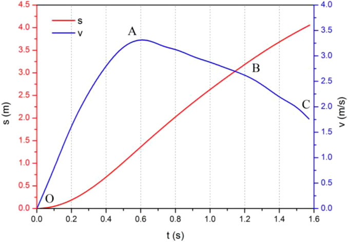
FIGURE 4. Change of velocity and position over time.
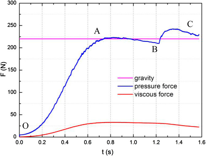
FIGURE 5. Evolution of forces acting on the control rod.
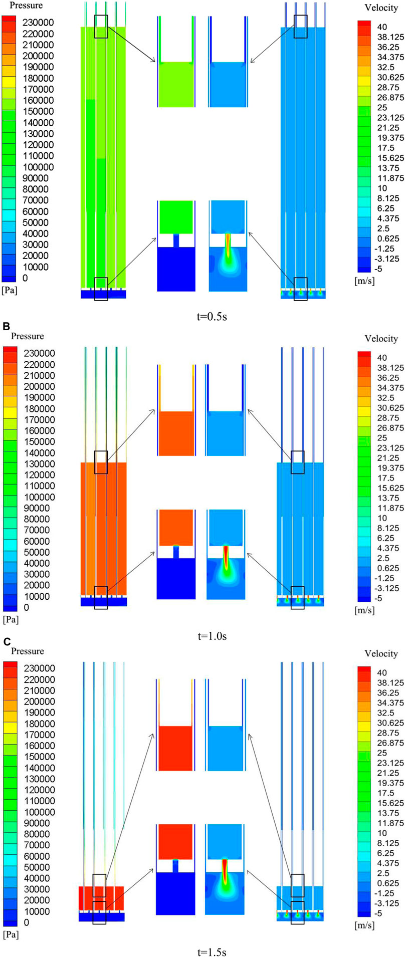
FIGURE 6. Evolution of pressure and velocity in the guide thimble. (A) t=0.5 s. (B) t=1.0 s. (C) t=1.5 s.
On the whole, it took about 1.2 s for the bottom of the control rod to reach the lower buffer region and 1.57 s to insert wholly. Moreover, the terminal velocity of the control rod assembly was about 1.7 m/s, which was much smaller than that of the previous plate-type design. And, the impact load on the fuel assembly would decrease greatly. Therefore, it could be concluded that the design of the optimized fuel assembly and cruciform control rod were feasible for the SCWR in terms of the dropping behavior.
Mechanical Analysis
In order to improve the mechanical performance of the optimized fuel assembly, the outer wall thickness of the moderator box was increased from 0.8 to 2.0 mm. Thus, the mechanical analysis was conducted. For the optimized fuel assembly in Figure 2, the average temperature difference of the coolant and moderator inside the fuel assembly was up to 150°C. The pressure difference would exist between the assembly boxes and moderator boxes, which might cause the thermal deflection of assembly boxes and moderator boxes. Based on the study of Hofmeister et al. (2007), assuming the pressure difference of 50 kPa, the maximum deflection of wall thickness should be less than 0.1 mm when the gap between fuel rods and box walls of the optimized fuel assembly was only 0.5 mm as listed in Table 1, and the thermal deflection
where
Compared with the moderator box, the assembly box had the same wall thickness but longer side length, thus suffering the larger thermal deflection. The calculation result of Eq. 1 shows that the thermal deflection of the assembly box was about 0.086 mm, not exceeding the maximum deflection of 0.1 mm. Therefore, the mechanical properties of the optimized fuel assembly could meet the requirement of allowed thermal deflection.
Neutron Performance
CSR1000 was a thermal spectrum reactor with UO2 as the fuel, which was cooled and moderated by light water. Because of high outlet temperature under supercritical water condition, the coolant had a small density, which resulted in the under-moderated issue. In order to improve neutron moderation, moderator boxes were introduced as presented in Figure 2. The coolant flowed among the fuel rods between the assembly box and moderator box, while the water served as the moderator inside the moderator boxes and through the gaps between the adjacent assemblies.
Considering the water density along the height of the active core (Hofmeister et al., 2007), the gap between the adjacent assemblies, and the guide thimbles data (Table 1), the water-to-fuel ratio of the optimized fuel assembly was calculated. The average ratio was about 0.08, which was close to that of the typical PWR, with the water-to-fuel ratio of 0.1. Therefore, the optimized fuel assembly had a good neutron-moderating ability.
Moreover, the cross-sectional area of the absorber for the plate-type cruciform control rod is about 60 × π × 5.62/4 = 1,477.81 mm2, which was much smaller than that of the absorber for the rod-type cruciform control rod (17 × π × 72/4 = 2,616.95 mm2). Thus, it could be deduced that the control rod worth of the optimized rod-type control rod was larger than that of the previous plate-type design.
Conclusion
An optimized design of the SCWR fuel assembly for CSR1000 aiming at solving the hydraulic drop buffering issue of the cruciform control rod had been proposed in this article, which consisted of four subassemblies welded by four filler strips and 17 guide thimbles arranged close together in the cross-shaped passage. The analysis demonstrated that the dropping time and terminal velocity of the control rod met the need of the control rod drop design, and the mechanical property as well as the neutronic performance also met the requirements of the fuel assembly design, which had good feasibility and performance.
Data Availability Statement
The original contributions presented in the study are included in the article/Supplementary Material; further inquiries can be directed to the corresponding authors.
Author Contributions
FZ: numerical simulation, data processing, and writing draft paper. LZ: numerical simulation and data processing. Q-YR: data processing and writing—editing. TY: numerical simulation and data processing. HP: writing—reviewing and supervision. LF: investigation and validation, XL: project administration and funding support. RR: project administration and funding support. SH: data processing.
Funding
This work was supported by the National Key R&D Program of China (No. 2018YEE0116100).
Conflict of Interest
The authors declare that the research was conducted in the absence of any commercial or financial relationships that could be construed as a potential conflict of interest.
References
Bae, Y.-Y., Jang, J.-S., Kim, H.-Y., Yoon, H.-Y., Kang, H.-O., and Bae, K.-M. (2007). Research Activities on a Supercritical Pressure Water Reactor in Korea. Nucl. Eng. Tech. 39, 273–286. doi:10.5516/net.2007.39.4.273
Buongiorno, J., and MacDonald, P. (2003). Study of Solid Moderators for the thermal Spectrum Supercritical Water-Cooled Reactor (Neutronics, Thermo-Mechanicsand Cost). In Proceedings of ICONE-, 11. Tokyo, Japan, 20–23.
Castro, L., Franois, J., and García, C. (2020). Coupled Monte Carlo-CFD Analysis of Heat Transfer Phenomena in a Supercritical Water Reactor Fuel Assembly. Ann. Nucl. Energ. 141. doi:10.1016/j.anucene.2020.107312
Chen, J., Zhou, T., Liu, L., and Fang, X. (2017). Analysis on LOCA for CSR1000. Ann. Nucl. Energ. 110, 903–908. doi:10.1016/j.anucene.2017.07.026
Feng, L., and Zhu, F. (2016). Fuel Assembly Design for Supercritical Water-Cooled Reactor. J. Nucl. Eng. Radiat. Sci. 2, 011014.
Fischer, K., Schulenberg, T., and Laurien, E. (2009). Design of a Supercritical Water-Cooled Reactor with a Three-Pass Core Arrangement. Nucl. Eng. Des. 239, 800–812. doi:10.1016/j.nucengdes.2008.12.019
Hofmeister, J., Waata, C., Starflinger, J., Schulenberg, T., and Laurien, E. (2007). Fuel Assembly Design Study for a Reactor with Supercritical Water. Nucl. Eng. Des. 237, 1513–1521. doi:10.1016/j.nucengdes.2007.01.008
Leung, L. (2015). Status of Canadian Generation IV National Program in Supportof SCWR Concept DevelopmentISSCWR-7. Helsinki: Finland. March 2015.
Reiss, T., Csom, G., Fehér, S., and Czifrus, S. (2010). The Simplified Supercritical Water-Cooled Reactor (SSCWR), a New SCWR Design. Prog. Nucl. Energ. 52, 177–189. doi:10.1016/j.pnucene.2009.06.006
Squarer, D., Schulenberg, T., Struwe, D., Oka, Y., Bittermann, D., Aksan, N., et al. (2003). High Performance Light Water Reactor. Nucl. Eng. Des. 221, 167–180. doi:10.1016/s0029-5493(02)00331-x
Wu, P., Gou, J., Shan, J., Zhang, B., and Li, X. (2014). Preliminary Safety Evaluation for CSR1000 with Passive Safety System. Ann. Nucl. Energ. 65, 390–401. doi:10.1016/j.anucene.2013.11.031
Xia, B., Yang, P., Wang, L., Ma, Y., Li, Q., Li, X., et al. (2013). Core Preliminary Conceptual Design of Supercritical Water-Cooled Reactor CSR1000. Nucl. Power Eng. 34 (1).
Xiao, C., Luo, Y., Zhang, H., Liu, X., and Du, H. (2017). Analysis of Control Rod Dropping and Buffering Behavior of Supercritical Water-Cooled Reactor Based on Dynamic Grid Technology. Nucl. Power Eng. 38 (S2), 79.
Xiong, J., and Cheng, X. (2014). Turbulence Modelling for Supercritical Pressure Heat Transfer in Upward Tube Flow. Nucl. Eng. Des. 270, 249–258. doi:10.1016/j.nucengdes.2014.01.014
Xiong, J., Cheng, X., and Yang, Y. (2015). Numerical Analysis on Supercritical Water Heat Transfer in a 2 × 2 Rod Bundle. Ann. Nucl. Energ. 80, 123–134. doi:10.1016/j.anucene.2015.02.005
Yamaji, A., Kamei, K., Oka, Y., and Koshizuka, S. (2005). Improved Core Design of the High Temperature Supercritical-Pressure Light Water Reactor. Ann. Nucl. Energ. 32, 651–670. doi:10.1016/j.anucene.2004.12.006
Yang, T., Liu, X., and Cheng, X. (2012). Optimization of Multilayer Fuel Assemblies for Supercritical Water-Cooled Reactors with Mixed Neutron Spectrum. Nucl. Eng. Des. 249, 159–165. doi:10.1016/j.nucengdes.2011.07.023
Keywords: supercritical water-cooled reactor (SCWR), fuel assembly, optimization, CSR, control rod property
Citation: Zhu F, Zheng L, Ren Q-Y, Yue T, Pang H, Feng L, Li X, Ran R and Huang S (2021) Optimization of a Fuel Assembly for Supercritical Water-Cooled Reactor CSR1000. Front. Energy Res. 9:678741. doi: 10.3389/fenrg.2021.678741
Received: 10 March 2021; Accepted: 01 June 2021;
Published: 22 June 2021.
Edited by:
Jinbiao Xiong, Shanghai Jiao Tong University, ChinaCopyright © 2021 Zhu, Zheng, Ren, Yue, Pang, Feng, Li, Ran and Huang. This is an open-access article distributed under the terms of the Creative Commons Attribution License (CC BY). The use, distribution or reproduction in other forums is permitted, provided the original author(s) and the copyright owner(s) are credited and that the original publication in this journal is cited, in accordance with accepted academic practice. No use, distribution or reproduction is permitted which does not comply with these terms.
*Correspondence: Fawen Zhu, emh1ZmF3ZW4xOTgzQDEyNi5jb20=; Quan-Yao Ren, cmVucXVhbnlhb0Bmb3htYWlsLmNvbQ==