 Wei Teng
 Yuejiao Wang
- State Grid Shandong Electric Power Research Institute, Jinan, China
DC power distribution systems will play an important role in the future urban power distribution system, while the charging and discharging requirements of electric vehicles have a great impact on the voltage stability of the DC power distribution systems. A robust control method based on H∞ loop shaping method is proposed to suppress the effect of uncertain integration on voltage stability of DC distribution system. The results of frequency domain analysis and time domain simulation show that the proposed robust controller can effectively suppress the DC bus voltage oscillation caused by the uncertain integration of electric vehicle, and the robustness is strong.
Introduction
Electric vehicles have become an important part of the low-carbon economy and the world is also in the stage of transformation from fuel vehicles to new energy vehicles (Needell et al., 2016; Wang et al., 2019; Ding et al., 2020; Connor et al., 2021; Zhang et al., 2021). Large-scale electric vehicles will be connected to the distribution network in the future. At present, the distribution network in the world is mainly in the form of AC power supply, and it is necessary to realize the charging of electric vehicles through AC/DC conversion links (Amamra and Marco, 2019; Li et al., 2019; Dong et al., 2021). So many electric energy conversion links will bring problems such as increased loss and reduced power efficiency (Rasheed et al., 2019). DC distribution systems has the advantages of low power loss, high power quality, and easy integration of DC distributed generations and loads (Rashad et al., 2018; Zhao et al., 2018; Dastgeer et al., 2019; Lin et al., 2019), which is gradually becoming the new direction of urban distribution system development in the future. However, the random charging of electric vehicles will cause uncertainty disturbance to the DC distribution system, which will easily lead to system oscillation and even instability (Staats et al., 1998; Tian et al., 2016).
Therefore, how to improve the stability of DC distribution system under the uncertain integration of electric vehicles has become a hot research topic at present. Scholars have put forward corresponding stability control methods from various points which can be summarized as follows:
1) Charging power adjustment method (Tabari and Yazdani, 2014; Tabari and Yazdanil, 2016). This strategy can effectively improve the system stability without changing system parameters or hardware, but it will have an impact on the charging rate of electric vehicles.
2) Virtual inertia control method. The first-order inertia compensation function is introduced into the outer loop of power control, which can improve the system damping and enhance the system stability after the electric vehicle is connected.
3) Virtual DC motor control method (Radwan and Mohamed, 2012; Alipoor et al., 2015). Based on the conventional double closed-loop control, the virtual DC motor is introduced to enhance the damping of the system by simulating the inertia of DC generator.
4) Nonlinear control (Tan et al., 2016; Tabari and Yazdani, 2014). Using nonlinear compensation function, fuzzy control, and other methods to improve system damping, but the control algorithm is more complex.
Most of the above studies do not consider the influence of uncertainty caused by random charging of electric vehicles. Therefore, this paper studies the robust stability control of electric vehicles connected to DC distribution system. In the manuscript, a model of the DC/DC converter control system is established and a robust stability controller based on H∞ loop shaping method is designed to improve the stability of DC bus voltage and suppress system oscillation under uncertainty.
The major contributions of this paper are summarized as follows:
1) The uncertain integration of electric vehicles and the parameter perturbation of the controller affect the voltage stability of the DC distribution system. Therefore, H∞ loop shaping method is introduced for DC/DC converters to improve the robust stability of the system.
2) A robust controller is designed for a DC distribution system with two EVs integration, and a high-order transfer function is obtained. For practical engineering application, the Hankel singular value algorithm is used to reduce the order. And the frequency domain analyses verify the control effect before and after order reduction.
3) A simulation model is established with DIgSILENT software, in which six scenarios are simulated. The simulation results show that the DC distribution system has good robustness to uncertain disturbances with the designed controller.
The remainder of this paper is organized as follows. In Topology of DC Distribution System with Electric Vehicle, a model of the flexible DC distribution system with electric vehicle is established. H∞Loop Shaping Method introduces the H∞ loop forming method, and the robust controller is designed for DC/DC converter. Frequency domain analysis is performed to verify the effectiveness of the robust controller in Frequency Domain Analysis. In Simulation Verification and Analysis, the effectiveness of the designed robust controller is verified by simulation. Finally, conclusions are summarized in Conclusion.
Topology of DC Distribution System With Electric Vehicle
The typical topology of DC distribution system is shown in Figure 1. Its main equipment includes interconnected AC/DC lines, interconnected AC/DC converters, DC distributed generations and DC loads, and DC/DC choppers, etc. The dynamic interaction among various equipment makes the stability of the system complex.
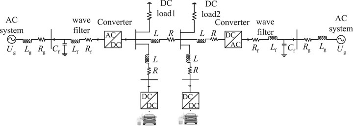
FIGURE 1. Structure drawing of double-end DC distribution system with electric vehicle.
The AC/DC interconnected converter in Figure 1 is based on the conventional three-phase bidirectional full-control rectifier bridge (Yazdani and Iravani, 2010), and its control mode adopts P-Udc droop control, and the DC/DC chopper is based on the conventional Buck-Boost circuit.
Control Strategy of Electric Vehicle
Conventional control strategies of electric vehicle chopper are mainly divided into constant power, constant current and constant voltage control (Peng et al., 2021). In Figure 1, droop control is adopted for both sides of interconnected AC/DC converters to maintain the DC voltage stability in the system, while constant power control is adopted for electric vehicle chopper to realize the power balance in the system. When the electric vehicle is connected to the system for charging without certainty, the power of the system at the beginning will mutate and deviate from Pref. According to the P-Udc droop control curve of AC/DC converter, as shown in Figure 2, when the power is abrupt, the reference value of the direct current voltage Udc,ref in the system will also be abrupt, which will cause the fluctuation of the direct current voltage Udc in the system.
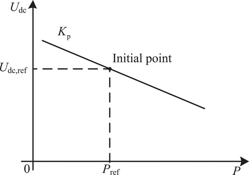
FIGURE 2. P-Udc droop control schematic diagram.
However, when a robust controller is attached to the DC/DC converter, the power imbalance in the system caused by the uncertain connection of loads will be greatly reduced, and the fluctuation of DC voltage in the system will be reduced. In Figure 2, Kp is the droop coefficient. The constant power control model of the chopper of electric vehicle is shown in the following Eqs (1) and (2).
Where:
Chopper constant power control strategy is based on the accurate mathematical model of the system to design the controller. However, due to the change of the operating environment, the change of the operating scene and the aging and damage of the equipment components, there will be some errors in the system model, so that the controller can not effectively control the system with errors. The robust control method based on H∞ loop shaping method is to design the controller for the system perturbed model, and the additional robust controller can ensure the voltage stability of the system under certain load disturbance and parameter perturbation.
Controlled Object Model
According to the actual control system, the control object of current inner loop is
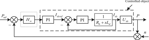
FIGURE 3. Block diagram of constant power control of chopper.
Therefore, it can be seen from the black dotted box on the right side of Figure 3 that the controlled object
The constant power control block diagram shown in Figure 3 is transformed into the standard feedback structure diagram shown in Figure 4, Wherein, K(s) represents the robust controller H∞, and d represents the output disturbance. According to Figure 4, the relationship between the system output power P and the noise signal n can be obtained:
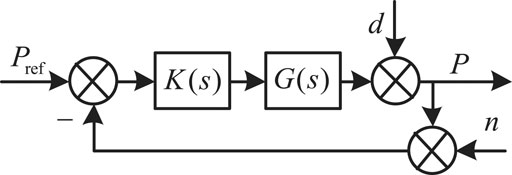
FIGURE 4. Standard feedback structure diagram.
As can be seen from Eq. 4, in order to reduce the influence of output disturbance d on system stability,
H∞ Loop Shaping Method
Design Steps of H∞ Loop Shaping Method
H∞ loop shaping method combines the advantages of H∞ technology and loop shaping method. When using this method to design robust controller, it can achieve the requirements of robust stability and robust performance at the same time. The design of robust controller is divided into the following three steps (Zhou et al., 1996):
1) Loop shaping. The requirements of the system for low, medium and high frequency are as follows: ① the low-frequency open-loop singular value is large, so as to improve the anti-disturbance ability of the system; ② the intermediate frequency curve transition is gentle, and its slope should be between (−40)dB/sec and (−20)dB/sec, so as to broaden the bandwidth of the system; ③ the high-frequency open-loop singular value is small, so as to improve the ability of the system to deal with unmodeled dynamics. According to the above requirements, the open-loop singular value shape
Among them, parameter a determines the low-frequency gain, b and c are used to adjust the cut-off frequency of the singular value curve, and d represents the steady-state error of the system.
2) Robust stabilization.
The maximum robust stability margin is calculated:
Where N(s) and M(s) are the normalized left coprime decomposition of the expected system
3) Select
Robust Controller Design
The structure diagram of double terminal DC distribution system is established as shown in Figure 1, in which the parameters of DC distribution system and the parameters of each converter are shown in Tables 1, 2 respectively.
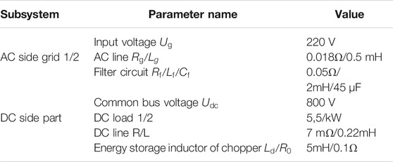
TABLE 1. DC distribution system parameters.
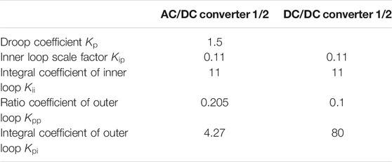
TABLE 2. Converter control parameters.
From Eq. 3, the open-loop transfer function of the controlled object is obtained as follows:
According to the requirements of loop forming in 1) Loop shaping, the expected open-loop singular value curve is selected as follows:
Because the order of the controller is 8, which is not conducive to practical engineering application, Hankel singular value algorithm is used to reduce the order, as shown in Eq. 10:
Comparing the frequency response curves of the robust controller before and after order reduction, as shown in Figure 5, it can be found that the control effect is basically the same before and after order reduction.
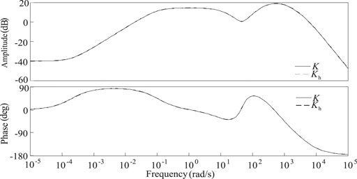
FIGURE 5. The frequency response curves of the robust controller before order reduction and after order reduction.
Frequency Domain Analysis
The curves of open-loop singular value and closed-loop singular value of the system before and after the additional robust controller for EVs are compared, as shown in Figures 6, 7 respectively. It can be found that the low-frequency gain of the open-loop singular value is larger and the high-frequency value decays rapidly by adding the robust controller, and the low-frequency amplitude of the closed-loop singular value is 0 and the peak is smaller after adding the robust controller, which is conducive to the signal tracking and disturbance suppression.
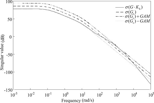
FIGURE 6. Open-loop singular value curve after adding robust controller.
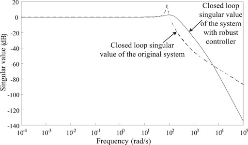
FIGURE 7. The closed-loop singular value curves of the system before and after the addition of the robust controller.
Simulation Verification and Analysis
In order to verify the effectiveness of the designed robust controller, the system shown in Figure 1 is built in DIgSILENT simulation software, in which two DC buses are used to simulate different integrated points of electric vehicles. Using the control variable method, only the analyzed parameters and load disturbance are variable. This paper analyzes the voltage fluctuation of DC distribution system before and after adding robust controller when one or two electric vehicles are connected with preset chopper parameters (Table 2) and the proportion and integral coefficient of chopper power outer loop and current inner loop change.
In this paper, the following six working conditions are simulated and analyzed.
Condition 1:when an electric vehicle is connected (Chopper operates with parameters in Table 2). The left DC bus is connected to the electric vehicle at 10 s, and the simulation ends at 15 s. The fluctuation of DC voltage of left DC bus before and after adding robust controller is shown in Figure 8.It can be seen from Figure 8 that when an electric vehicle is connected to the system, the DC bus voltage oscillates, and the oscillation amplitude is large, which makes the stability problem of the system decrease; while the oscillation amplitude of the system with a robust controller is small, and the adjustment time is short, because the system with a robust controller is less sensitive to the integration of the electric vehicle, and can still maintain the operation of the system in a better station.
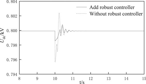
FIGURE 8. DC bus voltage waveform when an electric vehicle is connected to the system.
Condition 2:when two electric vehicles are connected at the same time (Chopper operates with parameters in Table 2). The two DC buses are connected to the electric vehicle at 10 s, and the simulation ends at 15 s. The fluctuation of DC voltage of left DC bus before and after adding robust controller is shown in Figure 9.It can be seen from Figure 9 that when two electric vehicles are connected to the system, the DC bus voltage impulse system is larger and the oscillation time is longer than when one electric vehicle is connected to the system; similarly, adding a robust controller based on uncertainty modeling can reduce the oscillation amplitude and the regulation time of the system.
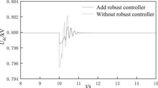
FIGURE 9. DC bus voltage waveform when two electric vehicle is connected to the system.
Condition 3:when an electric vehicle is connected, its chopper parameter
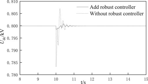
FIGURE 10. DC bus voltage waveform when chopper
Condition 4:
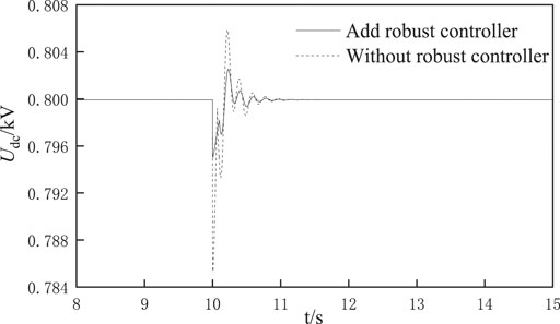
FIGURE 11. DC bus voltage waveform when chopper
Condition 5:when an electric vehicle is connected, its chopper parameter
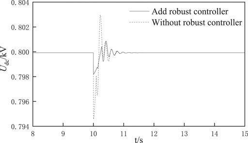
FIGURE 12. DC bus voltage waveform when chopper
Condition 6:when an electric vehicle is connected, its chopper parameter
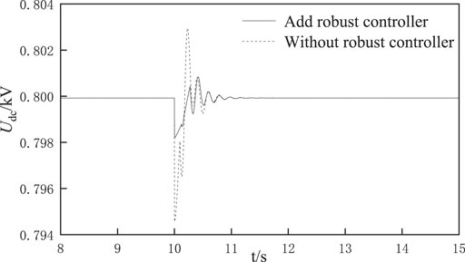
FIGURE 13. DC bus voltage waveform when chopper
Conclusion
In order to suppress the influence of uncertain integration of electric vehicles in DC distribution systems, a robust stability controller is designed based on loop shaping method in this paper, with the advantages of.
1) The robust controller can improve the voltage stability of the system effectively, without establishing the precise mathematical model of the system, and the sensitivity to load disturbance and parameter perturbation is weak.
2) When the order of robust controller is high and it is difficult to be used in engineering practice, Hankel singular value algorithm can be used to reduce the order, and the control effect before and after reduction is basically the same.
Data Availability Statement
The original contributions presented in the study are included in the article/supplementary material, further inquiries can be directed to the corresponding author.
Author Contributions
Conceptualization, WT, YW, SS, YC, PY, and SW; methodology, WT, YW, and SS; validation, WT, PY, YC, SW, and SS; formal analysis, WT, YW, and SW; writing-original draft preparation, WT, YW, and SW; writing-review and editing, WT, SS, and YW; All authors have read and agreed to the published version of the manuscript.
Funding
The Science and Technology Project of State Grid Shandong Electric Power Company, “Research on the Application of Flexible Direct Current Transmission Technology in Shandong Power Grid under the Framework of New Generation Power System” (grant number 52062618008J).
Conflict of Interest
The authors declare that the research was conducted in the absence of any commercial or financial relationships that could be construed as a potential conflict of interest.
Publisher’s Note
All claims expressed in this article are solely those of the authors and do not necessarily represent those of their affiliated organizations, or those of the publisher, the editors and the reviewers. Any product that may be evaluated in this article, or claim that may be made by its manufacturer, is not guaranteed or endorsed by the publisher.
References
Alipoor, J., Miura, Y., and Ise, T. (2015). Power System Stabilization Using Virtual Synchronous Generator with Alternating Moment of Inertia. IEEE J. Emerg. Sel. Top. Power Electron. 3 (2), 451–458. June. doi:10.1109/JESTPE.2014.2362530
Amamra, S.-A., and Marco, J. (2019). Vehicle-to-Grid Aggregator to Support Power Grid and Reduce Electric Vehicle Charging Cost. IEEE Access 7, 178528–178538. doi:10.1109/ACCESS.2019.2958664
Connor, W. D., Wang, Y., Malikopoulos, A. A., Advani, S. G., and Prasad, A. K. (2021). Impact of Connectivity on Energy Consumption and Battery Life for Electric Vehicles. IEEE Trans. Intell. Veh. 6 (1), 14–23. March 2021. doi:10.1109/TIV.2020.3032642
Dastgeer, F., Gelani, H. E., Anees, H. M., Paracha, Z. J., and Kalam, A. (2019). Analyses of Efficiency/energy-Savings of DC Power Distribution Systems/microgrids: Past, Present and Future. Int. J. Electr. Power Energ. Syst. 104, 89–100. doi:10.1016/j.ijepes.2018.06.05710.1016/j.ijepes.2018.06.057
Ding, X., Wang, Z., Zhang, L., and Wang, C. (2020). Longitudinal Vehicle Speed Estimation for Four-Wheel-Independently-Actuated Electric Vehicles Based on Multi-Sensor Fusion. IEEE Trans. Veh. Technol. 69 (11), 12797–12806. Nov. 2020. doi:10.1109/TVT.2020.3026106
Dong, L., Wang, C., Li, M., Sun, K., Chen, T., and Sun, Y. (2021). User Decision-Based Analysis of Urban Electric Vehicle Loads. CSEE J. Power Energ. Syst. 7 (1), 190–200. Jan. doi:10.17775/CSEEJPES.2020.00850
Tan, L., Wu, B., Rivera, S., Ise, T., et al. (2016). Comprehensive DC Power Balance Management in High-Power Three-Level DC–DC Converter for Electric Vehicle Fast Charging. IEEE Trans. Power Electron. 31 (1), 89–100.
Li, Y., Zhao, T., Liu, C., Zhao, Y., Wang, P., Gooi, H. B., et al. (2019). An Interactive Decision-Making Model Based on Energy and Reserve for Electric Vehicles and Power Grid Using Generalized Stackelberg Game. IEEE Trans. Ind. Applicat. 55 (4), 3301–3309. July-Aug. doi:10.1109/TIA.2018.2870834
Lin, G., Li, Y., Liu, J., and Li, C. (2019). Resonance Analysis and Active Damping Strategy for Shipboard DC Zonal Distribution Network. Int. J. Electr. Power Energ. Syst. 105, 612–621. doi:10.1016/j.ijepes.2018.08.038
Needell, Z. A., McNerney, J., Chang, M. T., and Trancik, J. E. (2016). Potential for Widespread Electrification of Personal Vehicle Travel in the united states. Nat. Energ. 1 (9), 16 112–116 118. Aug. doi:10.1038/nenergy.2016.112
Peng, K., Wei, Z., Chen, J., and Li, H. (2021). Hierarchical Virtual Inertia Control of DC Distribution System for Plug-And-Play Electric Vehicle Integration. Int. J. Electr. Power Energ. Syst. 128, 106769. doi:10.1016/j.ijepes.2021.106769
Radwan, A. A. A., and Mohamed, Y. A.-R. I. (2012). Assessment and Mitigation of Interaction Dynamics in Hybrid AC/DC Distribution Generation Systems. IEEE Trans. Smart Grid 3 (3), 1382–1393. doi:10.1109/TSG.2012.2201965
Rashad, M., Ashraf, M., Bhatti, A. I., and Minhas, D. M. (2018). Mathematical Modeling and Stability Analysis of DC Microgrid Using SM Hysteresis Controller. Int. J. Electr. Power Energ. Syst. 95, 507–522. doi:10.1016/j.ijepes.2017.09.001
Rasheed, A., Khan, S., Gelani, H. E., and Dastgeer, F. (2019). “AC vs. DC Home: An Efficiency Comparison,” in International Symposium on Recent Advances in Electrical Engineering. Islamabad, Pakistan: (RAEE), 1–6. doi:10.1109/RAEE.2019.8887064
Shen, X. (2016). Robust Control Based on Hinf Loop-Shaping of Variable-Speed Variable-Pitch Wind turbine[D]. Harbin: Harbin University of Science and Technology. in chinese.
Staats, P. T., Grady, W. M., Arapostathis, A., and Thallam, R. S. (1998). A Statistical Analysis of the Effect of Electric Vehicle Battery Charging on Distribution System Harmonic Voltages. IEEE Trans. Power Deliv. 13 (2), 640–646. doi:10.1109/61.660951
Tabari, M., and Yazdanil, A. (2016). A Mathematical Model for a Stability-Enhanced DC Distribution System for Power System Integration of Plug-In Electric vehicles[C]//IEEE Power and Energy Society General Meeting. Boston, USA: 5p. July 17-21. doi:10.1109/pesgm.2016.7741152
Tabari, M., and Yazdani, A. (2014). Stability of a Dc Distribution System for Power System Integration of Plug-In Hybrid Electric Vehicles. IEEE Trans. Smart Grid 5 (5), 2564–2573. doi:10.1109/TSG.2014.2331558
Tian, L. C., Wu, B., Rivera, S., and Yaramasu, V. (2016). Comprehensive DC Power Balance Management in High-Power Three-Level DC-DC Converter for Electric Vehicle Fast Charging. IEEE Trans. Power Electron. 34, 89–100. doi:10.1109/TPEL.2015.2397453
Wang, B., Dehghanian, P., Wang, S., and Mitolo, M. (2019). Electrical Safety Considerations in Large-Scale Electric Vehicle Charging Stations. IEEE Trans. Ind. Applicat. 55 (6), 6603–6612. Nov.-Dec. doi:10.1109/TIA.2019.2936474
Yazdani, A., and Iravani, R. (2010). Voltage-sourced Converters in Power System: Modeling, Control, and Applications. WileyIEEE Press. Voltage-Sourced Converters in Power Systems. doi:10.1002/9780470551578
Zhang, J., Salman, M., Zanardelli, W., Ballal, S., and Cao, B. (2021). An Integrated Fault Isolation and Prognosis Method for Electric Drive Systems of Battery Electric Vehicles. IEEE Trans. Transp. Electrific. 7 (1), 317–328. March 2021. doi:10.1109/TTE.2020.3025107
Keywords: DC distribution system, electric vehicles, H∞ loop shaping, robust control, uncertainty
Citation: Teng W, Wang Y, Sun S, Cheng Y, Yu P and Wang S (2021) Robust Stability Control for Electric Vehicles Connected to DC Distribution Systems. Front. Energy Res. 9:740698. doi: 10.3389/fenrg.2021.740698
Received: 13 July 2021; Accepted: 22 July 2021;
Published: 02 August 2021.
Edited by:
Yaxing Ren, University of Warwick, United KingdomReviewed by:
Yan Li, The Pennsylvania State University (PSU), United StatesXialin Li, Tianjin University, China
Copyright © 2021 Teng, Wang, Sun, Cheng, Yu and Wang. This is an open-access article distributed under the terms of the Creative Commons Attribution License (CC BY). The use, distribution or reproduction in other forums is permitted, provided the original author(s) and the copyright owner(s) are credited and that the original publication in this journal is cited, in accordance with accepted academic practice. No use, distribution or reproduction is permitted which does not comply with these terms.
*Correspondence: Wei Teng, MTYyMjcyNTE2MkBxcS5jb20=