 Cheng Wang
 Hongting Hua
 He Peng
 Ze Wang
- 1Intelligent Power Conversion Laboratory, Department of Electrical Engineering, Nanjing University of Science and Technology, Nanjing, China
- 2Control and Learning for Robotics and Autonomy Laboratory, Department of Mechanical and Energy Engineering, Southern University of Science and Technology, Shenzhen, China
Power electronics interfaced microgrid has become a major trend for modern power systems. In this paper, a three-phase microgrid system formed by multiple distributed energy storages (DES) converters is presented. To improve the reliability and flexibility, DESs are connected in parallel to feed the critical loads, and meanwhile, inject real power to the medium voltage (MV) distributed grid and the local dc bus through an interfacing smart transformer (ST). The ST is working at current control mode while the ac bus voltage is regulated in a sharing way through the DESs. However, due to the physical differences and different environment conditions, filter parameters are not likely to be matched for all the DES modules. Accurate load sharing is therefore the first challenging target. Furthermore, both DES module and ST can fail in event of single-point fault. Fast bus voltage restoring thus becomes the second challenging target. In this paper, the parameter mismatch is considered within the system modeling process. A control framework is then presented in form of a virtual current controller and a backstepping adaptive voltage controller. Adaptive laws are designed to fully compensate for the unknown dynamics within the system transient response. Convergence and boundedness of the signals in the closed-loop control system are demonstrated through rigorous Lyapunov-based stability analysis. Simulation results and experimental results are presented and have demonstrated the effectiveness of the proposed algorithm in terms of both fast bus voltage restoring and accurate power sharing.
Introduction
Microgrids are considered as the key building blocks of energy internets (Xiong et al., 2016; Harmon et al., 2018; Marzal et al., 2019; Liu et al., 2021; Wang et al., 2021) and have aroused great attentions in the last decade for their potential and the impact they may have in the coming future. Industrial/residential Microgrids are defined as low voltage systems comprised of loads, distributed generation units and storage devices, which are connected to the mains at a single Point of Common Coupling (PCC) (Sivarasu et al., 2015). Transformer is a key component to interface industrial/residential microgrids with the medium-voltage (MV) distributed grid. A smart transformer (ST) can achieve power factor correction, voltage sag ride through and harmonic elimination which are not available with a traditional line-frequency transformer (Huang, 2016; Huber and Kolar, 2019; Milczarek and Malinowski, 2020). The potentiality to use the ST in electric distribution as the enabling technology for Microgrids functionalities is much higher: the ST is supposed to replace the standard low-frequency transformer, connecting the MV grid to the LV grid and offer dc-connectivity, and services to Low-voltage and Medium Voltage grids (Andresen et al., 2017; Kumar et al., 2018; Ye et al., 2018; Zou et al., 2018; He et al., 2021). Therefore, the ST enabled ac industrial/residential microgrid as shown in Figure 1 is preferred in this paper.
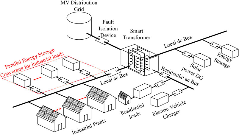
FIGURE 1. Configuration of ST enabled microgrids.
For traditional distribution networks, frequent tap/switch changing of the reactive components like transformers, capacitors etc. is necessary to achieve fast response to power fluctuation and voltage deviation, however, will also reduce component’s lifetime dramatically. As a promising alternative, the power electronics converters (PEC) interfaced distributed generators are more flexible (Wang et al., 2019; Zhang et al., 2019; Pugliese et al., 2020; Qian et al., 2020; Xiong et al., 2020). DES is an essential PEC enabler for modern industrial/residential Microgrids, to convert the ac or dc power produced by generators to ac powers at various voltage levels and frequencies and DC powers at various voltage levels, needed for supplying loads. In this way, distributed generations are able to be inserted into or bypassed from the industrial/residential bus. For high capacity applications, it is sometimes needed to use multiple modular distributed units due to the limitation of energy storage technology and the intimidating cost of a single large energy storage (Zhang et al., 2021).
Using multiple distribution units is more flexible and less susceptible against single-point failures. This is also a cost-effective solution for demands that grow through time. In this way, the parallel system can generate higher current to meet the large load demand. Despite the advantages, effective control of the parallel system is challenging due to the dynamic loading conditions, physical differences of the distributions, and the interactions of multiple modules. Due to the stochastic nature of both the renewable sources and the power consumed by the load, the inclusion of an advanced control is highly recommended in order to improve the system stability and its performance. To realize effective control of the parallel distributions, there are two major control objectives. The first objective is from system point of view, which is to regulate the output voltage to perfect sinusoid under nonlinear and fast-changing loading conditions. The second objective is from distributions point of view, which is to minimize the load current sharing errors among the DESs. As a system’s emergent power supply, good voltage regulation (root-mean-square/RMS voltage and frequency) is necessary. The control objective of voltage control can be realized by setting the voltage control reference to a sinusoidal signal. Circulating currents are current components flowing among the DESs. Ideally, all currents generated from DESs flow to the loads. Not well controlled system will have large circulating currents, which will degrade the energy efficiency and cause unbalanced load sharing even system or module failure in some conditions. The control objective on circulating current suppression can be realized by controlling the output currents to have the same profile other than the magnitude as the load current. During system upgrade, distributions of different capacity and parameters might be used. In addition, parameters of the real-world system might deviate from the nominal value and change slowly over time. Control under these unbalanced and unknown operating conditions is challenging. To meet the control objectives, the controller must be very fast and accurate so as to provide desired static and transient control performance.
To coordinate the control activities of multiple distributions, centralized solutions are good choices due to their easy access of global operating condition. In addition to the proportional-integration or proportional-resonant (PI/PR) based control algorithms that are widely used in power electronics, other types of control algorithms are also designed, including model predictive control (Karami et al., 2021), robust model-following control (Pascual et al., 2008), and sliding mode control (Darvishzadeh et al., 2012). The algorithms are evaluated through either simulation or hardware implementation. The algorithms have different kinds of limitations, such as requiring known load profiles and matched subsystem modules. In addition, these algorithms are not extensively tested under various loading conditions, linear/nonlinear, static/dynamic. It is known that centralized control algorithms are inflexible and susceptible to single-point-failures. Distributed control has been shown as a compromise of fully decentralized and centralized control to coordinate multiple devices especially under sparse communication infrastructure which is the usual case in today’s power distribution networks.
Droop control is the most popular distributed control solutions for power system applications (Yao et al., 2011). By adjusting the local control reference based on predefined droop characteristics, coordination of multiple subsystems can be realized. Major advantages of droop control include no inter-module communication, easy to design and implement. However, droop controls also suffer from various problems, such as unbalanced load sharing, voltage/frequency control deviation, etc. Thus, additional control modules are needed to correct these problems. To significantly improve control performance, advanced distributed control algorithms are needed. Designing such control algorithms require integrating multidisciplinary expertise especially in control and power electronics, where big gaps exist in-between. Once such control algorithms are designed and tested through offline simulation, it is necessary to further test it through hardware experimentation to evaluate its performance that are not foreseen under ideal model-based simulation studies.
In this paper, a distributed backstepping based control algorithm is presented for the Microgrid system. Convergence and boundedness of the signals in the closed-loop control system are demonstrated through rigorous Lyapunov-based stability analysis. The designed algorithm is distributed, works for unmatched DES modules and can realize predefined load sharing. The algorithm is implemented with multiple DSP-based control boards and tested under various operating conditions, including balanced and unbalanced distributions, linear and nonlinear loading conditions, constant and variable loading conditions, etc. Experimentation results demonstrate the effectiveness of the proposed control algorithm. The success of the designed control algorithm demonstrates that significantly improved control performance can be achieved by introducing advanced control techniques to power electronics.
The rest of the paper is organized as follows. The dynamic model of the Microgrid is introduced in System Configuration and Problem Description Section. The designed distributed control algorithm is presented in Distributed Adaptive Controller Design for DGs Section. The experimentation results are provided in Simulation and Experiment Studies Section. Concluding remarks are provided in Conclusion Section.
System Configuration and Problem Description
Figure 2 illustrates the simplified configuration of a ST enabled Microgrid, where the line impedances are incomparable with the output filter impedances. Multiple distributed generators (i.e. solar power system and wind power system), ST and variable loads are considered connected to a common ac bus. The model shown in Eq. 1 represents the dynamics of the R-L-C filters connecting the N DESs to the point of common coupling.
where
where,
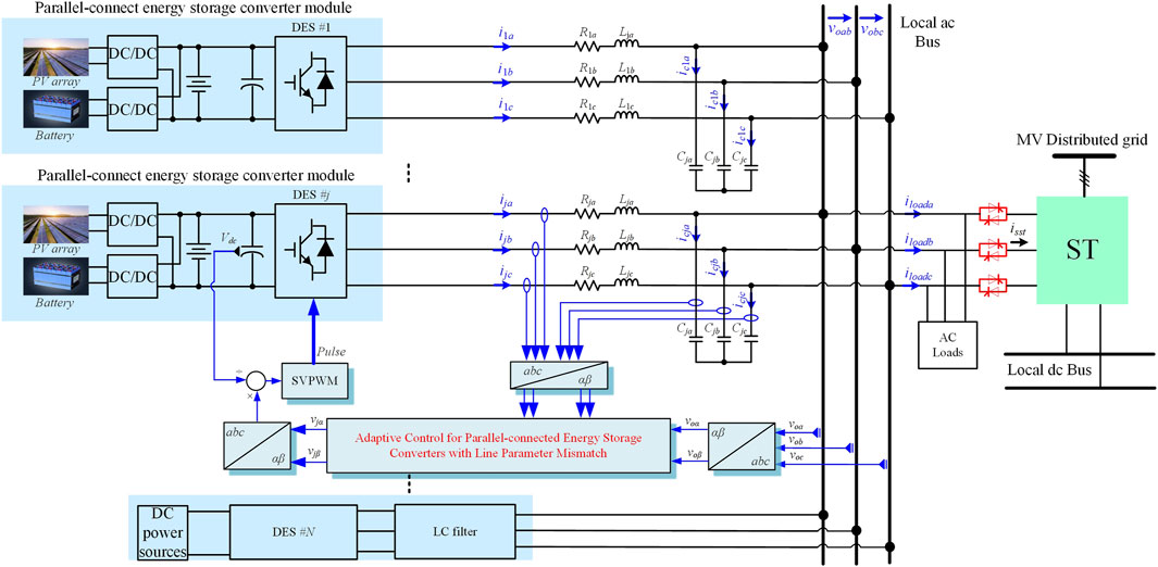
FIGURE 2. The simplified configuration of a ST enabled parallel-connected DES based microgrid.
And
An equivalent model of the paralleled-inverter based microgrid (taking one module for example), given in Figure 3, can be developed according to Eq. 2. As seen from the model, filter currents and ac bus voltages in phase-α are coupled with the ones in phase-β. The coupling parts are represented by dependent current sources in the circuit.
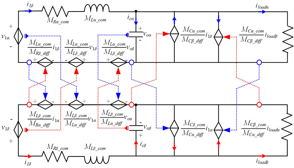
FIGURE 3. Equivalent circuit of a DES module in αβ stationary reference frame.
Note that, more modules require more interfacing line parameters. In practical, it is impossible to obtain the exact values of circuit parameters. Further, parameter drifts are very likely to happen with aging of inductors or capacitors. This is also the reason why each LCR filter parameter are assigned own variables in the modeling process. In the following, an adaptive algorithm is proposed for online tuning the control coefficients, which can reduce the impact of the parameter measurement or estimation error on the system performance in a wide operating range. Moreover, such an adaptive algorithm can improve system dynamic performance due to its direct backsteping design, thus can realize fast voltage restoring and load power sharing. The system performance coping with single-point failure, i.e., DES module fault or ST fault can be thus guaranteed.
Distributed Adaptive Controller Design for DGs
Traditionally, the ac bus voltage is regulated by the ST. Direct power control or direct current control is selected for DES modules (She et al., 2013). Such a way is straightforward and easy to implement. However, one of the main drawbacks is that the failure of the ST is not able to be tolerated. In this paper, the ST is working at current control mode while the ac bus voltage is regulated in a sharing way through the DES modules. In this way, each DES module is capable of regulating the bus voltage. The voltage restoring is faster once DES module/ST failure happens. In this section, a distributed adaptive controller is designed to maneuver the output voltage to track the reference trajectory
Virtual Current Control for Power Sharing
In αβ coordinates, the tracking error for the ac bus voltage is firstly defined as
Then, taking the time derivative of Eq. 3 yields
Consider the following Lyapunov function candidate
The time derivative of Eq. 5 is written as
where
According to the backstepping principle,
An ideal virtual controller
Define
where
with
for any
Adaptive Voltage Control
For simplicity consideration,
The error between the actual input
Thereafter, the following augmented Lyapunov function
where
Recalling the property of the projection algorithm in Eq. 11 and an assumption that lower and upper bounds of
Where,
Next, the actual control law
where
With the help of Assumption 1 and further assume that the load current
with
Observer Design
In previous subsection, the information of
Firstly, an voltage observer is proposed to obtain
where
for
along with the current observer output error
for
Lemma 1: Consider the observers designed in Eq 21, 22, then the following facts hold: 1) all signals of the observers are bounded; 2) the observer output errors Eq 23, 24 can be tuned arbitrarily small by chosen sufficient large observer gains
Then replacing
where
Thereafter, the output-feedback based controller is updated as
Replacing
In a similar way, Firstly, the voltage observer and estimate values for phase- β are given as
The virtual controllers and the update law for phase- β using designed observer can be figured out as expressed by
The stability analysis of the closed-loop system under output-feedback controller is shown in Theorem 2 included in the Supplementary Appendix.Figure 4 illustrates the control block diagram of a local inverter unit. The developed adaptive controller only requires the local measurements. Only a synchronization signal and no more interconnection communications among DGs are required.
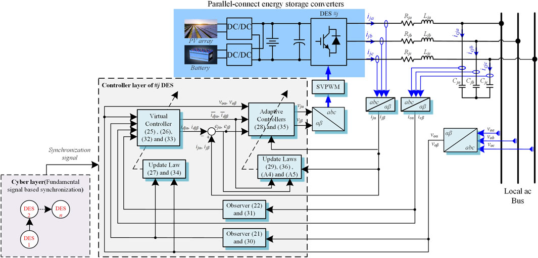
FIGURE 4. Control block diagram of a DES module.
Simulation and Experiment Studies
Simulation Verifications
In order to explore the performance of the proposed decoupling and adaptive control techniques, the simulation on a MATLAB/Simulink platform is conducted. A microgrid system formed by parallel-connected energy storage converters is applied in the simulation. Parameters of the system are summarized in Table 1.
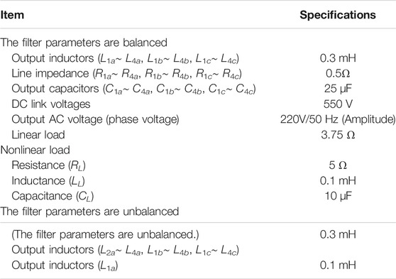
TABLE 1. System parameters in the simulation.
Figure 5 shows the three-phase simulation results including three scenarios, i.e., Case 1∼ Case 3. The waveforms from top to bottom are respectively about ac bus voltages, load currents, active power injected to the load from different modules, output currents of DES module #1∼#4. Zoomed-in three-phase waveforms of the rating steady state are shown at the right side of Figure 5.
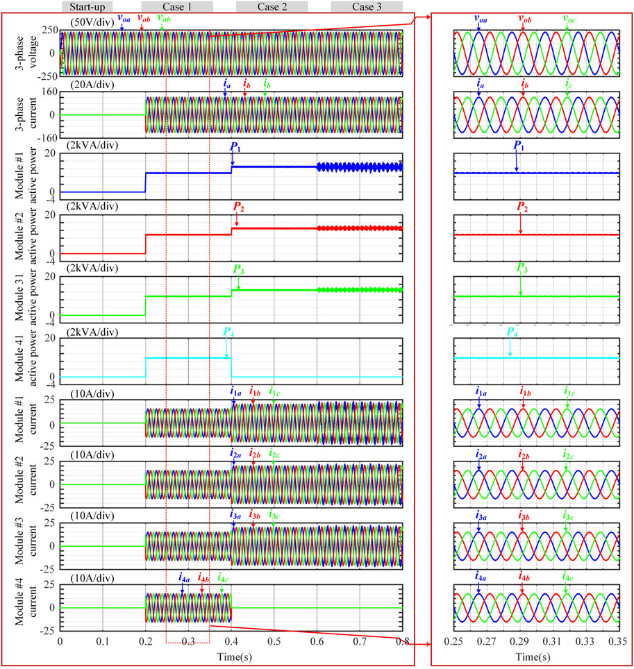
FIGURE 5. Three-phase simulation results by using proposed control including scenarios of 1) start up (from 0 to 0.5 s), 2) module without mismatch #1 case (from 0.2 to 0.4 s), 3) module failure #2 case (from 0.4 to 0.6 s) and 4) module-mismatch #3 case.
During the whole simulation interval, the control proposed in Distributed Adaptive Controller Design for DGs Section takes effect on the coordination for the four DES modules. The zooming waveforms for each scenario transition in Figure 5 are shown in Figure 6. Start process lasts for 0.2 s (from 0 to 0.2 s). At 0.2 s, the active power injected by the four modules, change from 0 to 5 kW (1.0p.u.). Accordingly, the total active power consumed by the load, increases to 5 kW. And the load current magnitude, Iload increases to 60.6 A. The transition lasts for a very short time interval. The voltage drops are acceptable [the maximum drop value is 16 V (0.073 p.u.), occurring in phase-b]. Afterwards, the load currents have good qualities, i.e., the THD is 0.85%. And the circulating currents are nearly zero, as shown in Figure 9 (before 0.4 s).
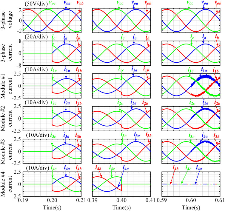
FIGURE 6. The zooming waveform for each scenario transition for the proposed control.
At 0.4 s, #1, #2 and #3 modules keep power injection but the one of #4 module is bypassed by a solid switch due to a sudden failure. The module failure shows little impact on the regulating of ac bus voltage, i.e. the power is balanced very well (Circulating currents are small enough). And the voltage quality is still good as expected (THD is not larger than 0.81%). At 0.6 s, the phase-a line inductance of #1 module changes to 0.1 mH (0.33p.u.). Unsymmetrical line parameters degrade the operation performance i.e., the circulating current (i1a-i2a) is increased. But the value is 5 A (0.082 p.u.), which is acceptable.
Note that, the simulation results of the conventional PI-based control (PI-based control scheme with a centralized structure) are also supplied in Figure 7 for comparisons. Simulation parameters are same as listed in Table 1. The waveforms from top to bottom are also respectively about ac bus voltages, load currents, active power injected to the load from different modules, output currents of DES module #1∼#4, And zoomed-in three-phase waveforms of the rating steady state are also provided at the right side of Figure 7.
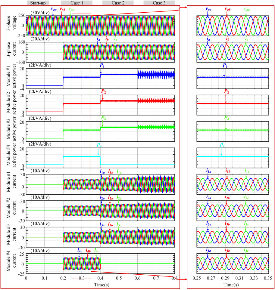
FIGURE 7. Three-phase simulation results by using PI-based control including scenarios of 1) start up (from 0 to 0.5 s), 2) module without mismatch #1 case (from 0.2 to 0.4 s), 3) module failure #2 case (from 0.4 to 0.6 s) and 4) module-mismatch #3 case (from 0.6 to 0.8 s).
Focally, Figure 8 presents the comparison between the proposed control and the PI-based control facing a step load change. For conventional PI based control, the maximum drop of ac bus voltage is large as 38 V. In contrast, for the proposed control, the value is only 16 V. Furthermore, Waveforms of the ac bus voltage tracking error and the circulating currents for comparison between the proposed adaptive control and PI-based control are intentionally added in Figure 9. The voltage tracking errors are nearly equal to each other, but the circulating current (i1a-i2a) in the PI-based control is larger than that of the proposed control (13 vs. 5 A).
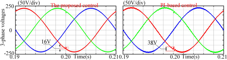
FIGURE 8. Simulation waveforms comparison facing a step load change.
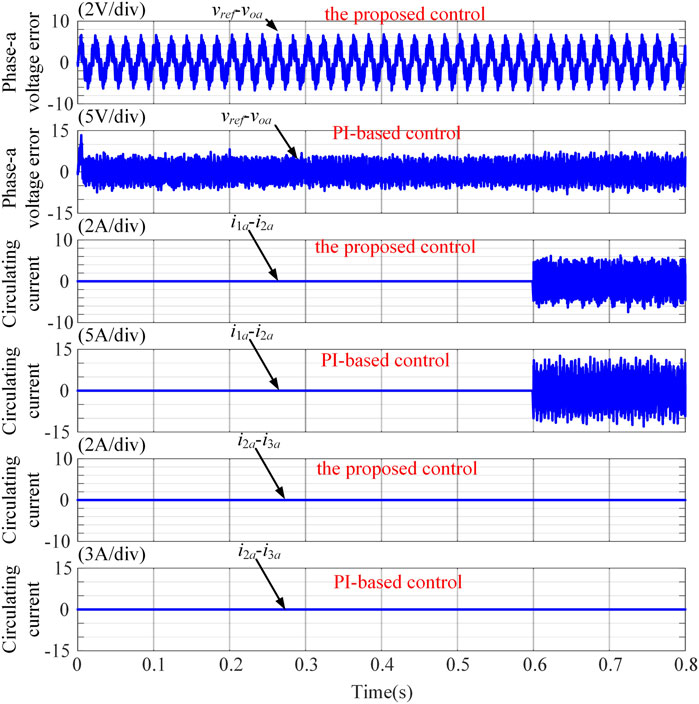
FIGURE 9. Simulation waveforms of phase-a voltage tracking error and circulating currents under linear load condition.
In order to better evaluate the performance of the proposed control solution, the non-linear load condition is considered. And it is also compared with the widely used PI-based control scheme. Figure 10 shows the simulation waveforms of phase-a voltage tracking error and circulating current between proposed control and PI-based control when connecting nonlinear load. The similar voltage tracking error/circulating currents conclusion applies to this non-linear load condition. Moreover, for PI-based control, the THD of the ac voltage is high as 5.34% under rating non-linear load (see Figure 11 after 0.2 s). However, the value of the proposed method is only 0.81%. Obviously, this conventional way cannot handle the non-linear load very well.
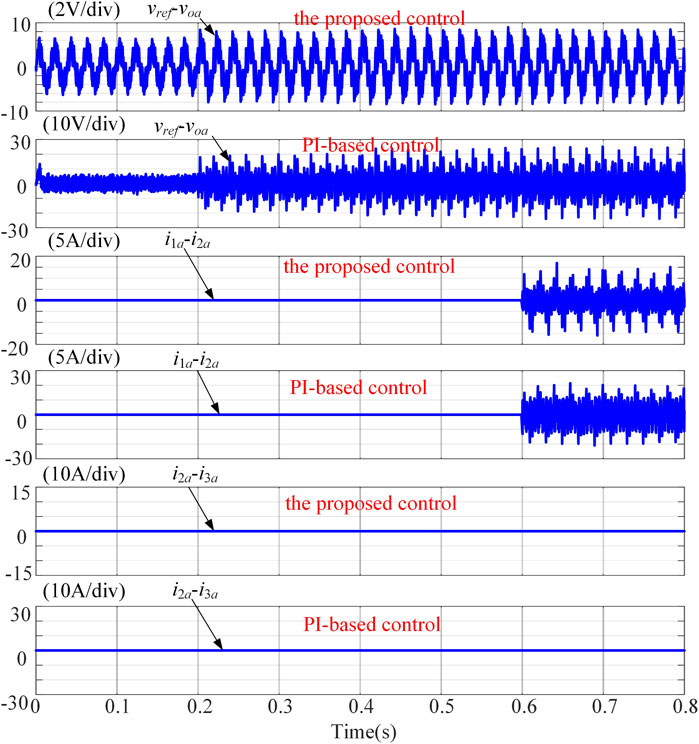
FIGURE 10. Simulation waveforms of phase-a voltage tracking error and circulating current under nonlinear load condition.
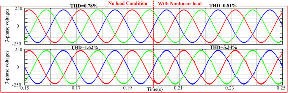
FIGURE 11. Three-phase simulation results between proposed control and PI-based control suffering from nonlinear load.
Lastly, it should be noted that, if a droop stage is employed, the PI-based method would need average power calculation. The sensed load current is a high frequency one, therefore requires high resolution sensors, wide bandwidth analog signal processing circuit, and high performance analog to digital converter for digital control. Furthermore, the calculation of the power is also not easy due to the complex integration operation, in which the calculation accuracy may be low. In this condition, the performance of the controller may not be guaranteed in the real hardware setup. By using the proposed control method, no additional current sensor is needed and high performance can be achieved.
Experiment Results for a Single-Phase Microgrid
The experiment verification is based on a setup shown in Figure 12, which consists of three DES sub-systems. Every sub-system has its own control platform and monitoring interfaces, i.e., control boards, external digital to analog converter (DAC) boards, personal computers and one oscilloscope. Each DG is composed by one DC power supply, one H-bridge inverter and one LC filter. And the three DGs are connected in parallel to share the load that can be switched between linear load and nonlinear load. The photo of LC filters and loads is shown at the right bottom of Figure 12. The configuration of nonlinear load is illustrated in the below. Parameters of the system are presented in Table 2. The designed adaptive controller is implemented on a TSM320F28346 DSP. In this control scheme, each controller is used to control its own DG. The adaptive controller’s parameters are chosen as
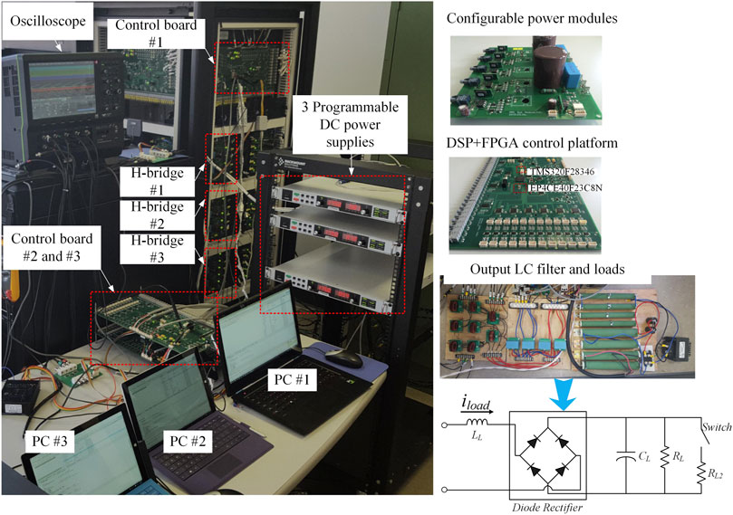
FIGURE 12. Experimental setup.
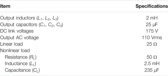
TABLE 2. Experimental parameters.
In reality, even the same batch of components has different parameters that deviate slightly from the nominal value. For control implementation with DSP control board, one major issue is with the synchronization of the control activities. Even if the control signals are periodically synchronized, the control activities between synchronization cannot be guaranteed due to inaccuracy and fluctuation of DSP clocks. Even though clock speed cannot be adjusted, control signal synchronization update can be realized by synchronizing the timing of control update with a common/accurate reference signal. Accurate synchronization is critical to achieve expected performance. Although the synchronization function provided by manufacture, such as the ePWM sync pulse signal of TI TMS320C28346, is easy to implement, experimental studies show that the high-frequency signal is susceptible to switching noises. When power circuit works at a relatively high voltage level i.e., 170 V DC link voltage in the experiment, the switching noises will cause random losses of sync pulse signals. Since the time step is synchronized to the successfully delivered pulses, unreliable synchronization signal will seriously deteriorate the control performance. To improve synchronization reliability, a low-bandwidth synchronization technique is designed and implemented as introduced below. The synchronization signal is carried with a fundamental signal. The rising edge will initiate synchronization and the duration of the signal will be used for phase shift evaluation. During implementation, the synchronization signal can be generated with one control board and then broadcasted to neighboring control boards one after another. In addition to the leader-follower communication scheme, centralized or GPS-based pseudo-distributed schemes can also be implemented.
Figure 13 shows the results of the low bandwidth synchronization. Before the trigging of the synchronization, each calculation cycle is determined by dividing the DSP system clock with a fixed ratio. The system clock of each DSP is configured as 300 MHz. Thus the initial frequency dividing ratio is set as 25,000 to get 12 kHz sampling and switching time-step. Since the DSP clocks are mismatched with each other, the shifting of calculation cycles is introduced, which is shown in Figure 13A. Through activating the synchronization, the sub-system # 1 sends fundamental square signals to sub-system #2 and #3. Inside each sub-system, the frequency dividing ratio is then adjusted by using the loop shown in Figure 4. The steady results with synchronization are shown in Figure 13B, where three cycles are synchronized with each other well. Moreover, the closed loop in Figure 4 regulates the periods of cycles dynamically inside every calculation cycle to guarantee the subsystems are always well synchronized for the imposing of the distributed adaptive algorithms.
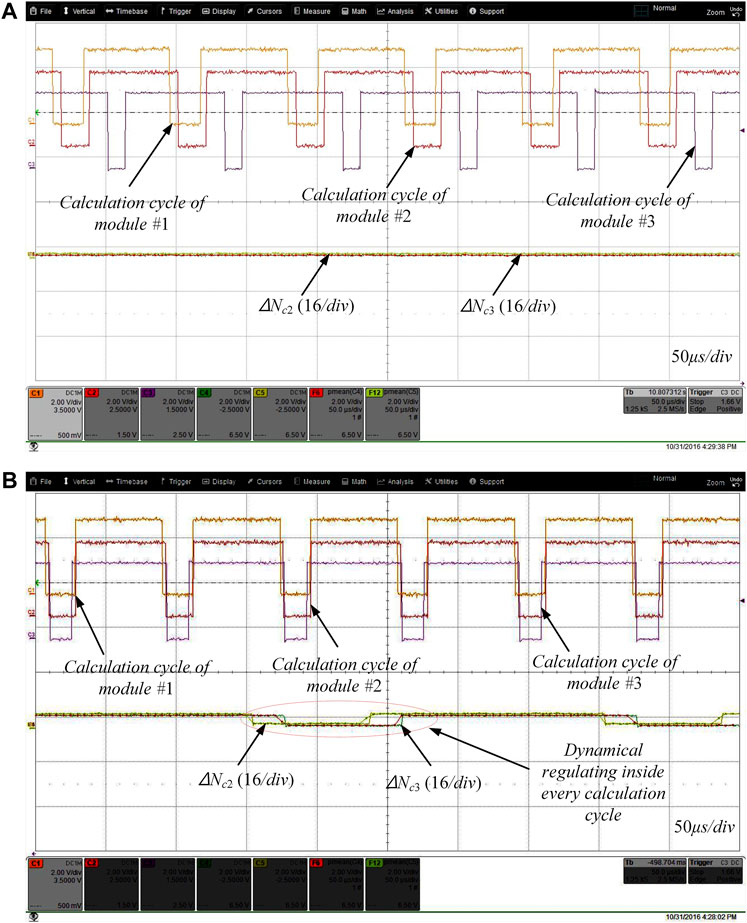
FIGURE 13. Experimental results of the low bandwidth synchronization: (A) Zooming-in of the experiment results when without synchronization and (B) Zooming-in of the experiment results when with synchronization.
Through the low bandwidth synchronization, only local information is used for each adaptive controller in experiments. In Figure 14, the results of linear load in balanced system parameter case (L1 = L2 = L3, C1 = C2 = C3) are given out. A good tracking performance of the output voltage is achieved by the adaptive controller under the balanced condition. Although the FFT results of the output voltage have harmonic components, the amplitudes of 3rd, 5th, 7th etc. harmonics are less than 2.5 V which is approximately 1.6% of fundamental frequency component. The total harmonic distortion (THD) is less than 1.8%. Moreover, since the differences between modules currents (i1-i2, i2-i3, i3-i1) are almost zero as shown in Figure 14, the load current is well shared. Results of nonlinear load case is presented in Figure 15. In this case, the load is also equivalently shared by modules. Although the output voltage performance is degraded compared to the linear case, the THD is just 3.2% which satisfies related standards.
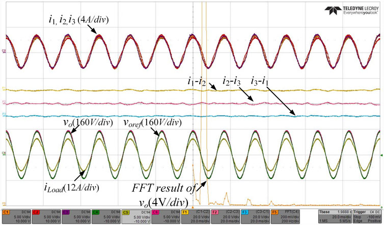
FIGURE 14. Linear load under balanced condition.
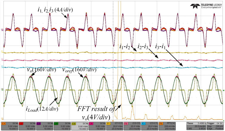
FIGURE 15. Nonlinear load under balanced condition.
In the previous two cases, the system parameters are chosen as presented in Table 2. However, the practical parameters of different LC filters cannot be exactly same. Even the inductance and capacitance will be varied slowly during the operation. Thence, unbalanced cases are considered. The inductance of LC filter of module #1 is reduced to 1 mH. Figures 16, 17 depict the corresponding results. As shown, the output voltage performances of both the linear load case and nonlinear load case under unbalanced filter parameters condition are almost the same as the ones under balanced condition. Therefore, the proposed control method can achieve a good voltage tracking performance with filer parameter differences. However, the current sharing performance is degraded especially in the nonlinear load case. The current differences between DGs are smaller than 0.5 A which is acceptable for a distributed control scheme with unknown system parameters.
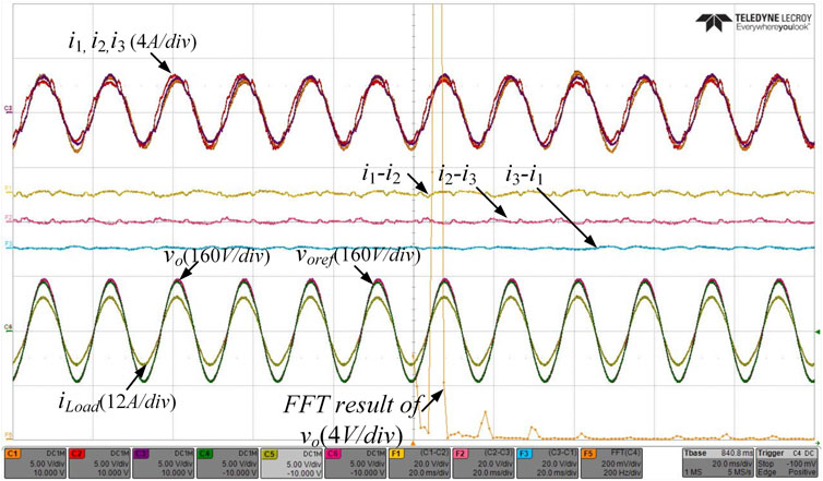
FIGURE 16. Linear load under unbalanced condition (L1 = 1 mH, L2 = L3 = 2 mH).
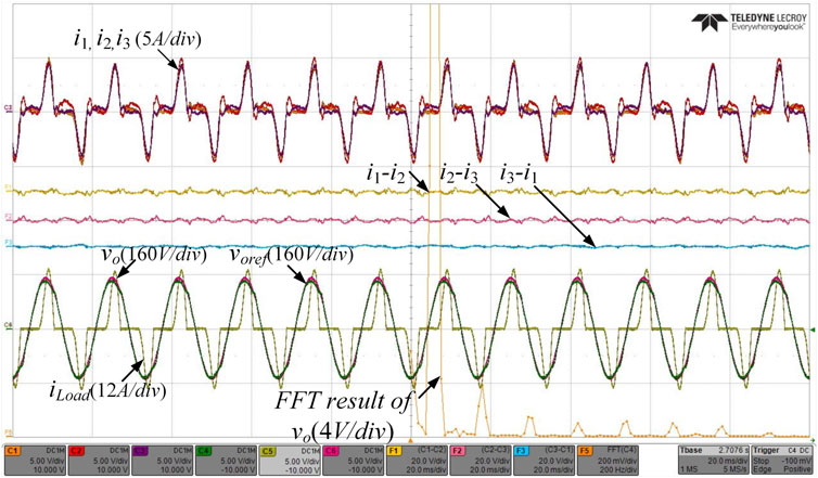
FIGURE 17. Nonlinear load under unbalanced condition (L1 = 1mH, L2 = L3 = 2 mH).
Conclusion
In this paper, a backstepping based adaptive controller has been proposed for a microgrid formed by parallel-connected energy storage converters. The parameter mismatch is considered within the system modeling process. Furthermore, the unknown system dynamics have been compensated by designed adaptive laws. According to the standard Lyapunov synthesis, the hierarchical control system including a virtual current controller and a backstepping adaptive voltage controller has been proved to be bounded with reasonable assumptions. Both simulation and experimental results were presented to show the high performance of the developed controller in terms of voltage tracking (i.e., a low THD even in the nonlinear load case) and load power sharing (i.e., little circulating current even with unbalanced line parameters). In addition, when coping with single-point DES module failure, the effectiveness of the proposed algorithm for fast voltage restoring has been verified.
Data Availability Statement
The original contributions presented in the study are included in the article/Supplementary Material, further inquiries can be directed to the corresponding author.
Author Contributions
Conceptualization and original draft preparation, CW; writing and simulation validation, HH; resources and supervision, ZW; review and experiment verification, HP. All authors have read and agreed to the published version of the manuscript.
Funding
Project supported by Natural Science Foundation of Jiangsu Province (BK20190461).
Conflict of Interest
The authors declare that the research was conducted in the absence of any commercial or financial relationships that could be construed as a potential conflict of interest.
Publisher’s Note
All claims expressed in this article are solely those of the authors and do not necessarily represent those of their affiliated organizations, or those of the publisher, the editors and the reviewers. Any product that may be evaluated in this article, or claim that may be made by its manufacturer, is not guaranteed or endorsed by the publisher.
Supplementary Material
The Supplementary Material for this article can be found online at: https://www.frontiersin.org/articles/10.3389/fenrg.2021.770372/full#supplementary-material
References
Andresen, M., Ma, K., De Carne, G., Buticchi, G., Blaabjerg, F., and Liserre, M. (2017). Thermal stress analysis of medium-voltage converters for smart transformers. IEEE Trans. Power Electron. 32 (6), 4753–4765. doi:10.1109/tpel.2016.2600270
Behtash, S. (1990). Robust output tracking for non-linear systems. Int. J. Control. 51 (6), 1381–1407. doi:10.1080/00207179008934141
Darvishzadeh, S., Rahmati, A., and Abrishamifar, A. (2012). “Hierarchical sliding mode control of paralleling single-phase UPS inverters”, in Proc. IEEE 3rd Int. Symp. Power Electron (Tehran, Iran: IEEE), 164–169. doi:10.1109/pedstc.2012.6183318
Ge, S. S., Hang, C. C., and Tao Zhang, T. (1999). Adaptive neural network control of nonlinear systems by state and output feedback. IEEE Trans. Syst. Man. Cybern. B. 29 (6), 818–828. doi:10.1109/3477.809035
Harmon, E., Ozgur, U., Cintuglu, M. H., de Azevedo, R., Akkaya, K., and Mohammed, O. A. (2018). The Internet of Microgrids: A Cloud-Based Framework for Wide Area Networked Microgrids. IEEE Trans. Ind. Inf. 14 (3), 1262–1274. doi:10.1109/tii.2017.2785317
He, Z., Hu, J., Lin, L., and Zeng, P. (2021). Modelling and analysis of half‐/full‐bridge hybrid MMC when riding through DC‐side pole‐to‐ground fault. High Voltage, 1–14. doi:10.1049/hve2.12144
Huang, A. Q. (2016). Medium-Voltage Solid-State Transformer: Technology for a Smarter and Resilient Grid. EEE Ind. Electron. Mag. 10 (3), 29–42. doi:10.1109/mie.2016.2589061
Huber, J. E., and Kolar, J. W. (2019). Applicability of Solid-State Transformers in Today's and Future Distribution Grids. IEEE Trans. Smart Grid 10 (1), 317–326. doi:10.1109/tsg.2017.2738610
Karami, Z., Shafiee, Q., Khayat, Y., Yaribeygi, M., Dragicevic, T., and Bevrani, H. (2021). Decentralized Model Predictive Control of DC Microgrids With Constant Power Load. IEEE J. Emerg. Sel. Top. Power Electron. 9 (1), 451–460. doi:10.1109/jestpe.2019.2957231
Kumar, C., Zhu, R., Buticchi, G., and Liserre, M. (2018). Sizing and SOC Management of a Smart-Transformer-Based Energy Storage System. IEEE Trans. Ind. Electron. 65 (8), 6709–6718. doi:10.1109/tie.2017.2784389
Liu, J., Bevrani, H., and Ise, T. (2021). A design-oriented Q-V response modeling approach for grid-forming distributed generators considering different operation modes. IEEE J. Emerg. Sel. Top. Power Electron., 1. doi:10.1109/JESTPE.2021.3057517
Marzal, S., González-Medina, R., Salas-Puente, R., Garcerá, G., and Figueres, E. (2019). An Embedded Internet of Energy Communication Platform for the Future Smart Microgrids Management. IEEE Internet Things J. 6 (4), 7241–7252. doi:10.1109/jiot.2019.2915389
Milczarek, A., and Malinowski, M. (2020). Comparison of Classical and Smart Transformers Impact on MV Distribution Grid. IEEE Trans. Power Deliv. 35 (3), 1339–1347. doi:10.1109/tpwrd.2019.2941641
Pascual, M., Garcera, G., Figueres, E., and Gonzalez-Espin, F. (2008). Robust Model-Following Control of Parallel UPS Single-phase Inverters. IEEE Trans. Ind. Electron. 55 (8), 2870–2883. doi:10.1109/tie.2008.918602
Pugliese, S., Buticchi, G., Mastromauro, R. A., Andresen, M., Liserre, M., and Stasi, S. (2020). Soft-Start Procedure for a Three-Stage Smart Transformer Based on Dual-Active Bridge and Cascaded H-Bridge Converters. IEEE Trans. Power Electron. 35 (10), 11039–11052. doi:10.1109/tpel.2020.2977226
Qian, T., Liu, Y., Zhang, W., Tang, W., and Shahidehpour, M. (2020). Event-Triggered Updating Method in Centralized and Distributed Secondary Controls for Islanded Microgrid Restoration. IEEE Trans. Smart Grid 11 (2), 1387–1395. doi:10.1109/tsg.2019.2937366
Sivarasu, S. R., Chandira Sekaran, E., and Karthik, P. (2015). Development of renewable energy based microgrid project implementations for residential consumers in India: Scope, challenges and possibilities. Renew. Sust. Energ. Rev. 50, 256–269.
Wang, C., Duan, J., Fan, B., Yang, Q., and Liu, W. (2019). Decentralized High-Performance Control of DC Microgrids. IEEE Trans. Smart Grid 10 (3), 3355–3363. doi:10.1109/tsg.2018.2825199
Wang, Y., Nguyen, T. L., Syed, M. H., Xu, Y., Guillo-Sansano, E., Nguyen, V.-H., et al. (2021). A Distributed Control Scheme of Microgrids in Energy Internet Paradigm and its Multisite Implementation. IEEE Trans. Ind. Inf. 17 (2), 1141–1153. doi:10.1109/tii.2020.2976830
Xiong, L., Liu, X., Liu, Y., and Zhuo, F. (2020). Modeling and stability issues of voltage-source converter dominated power systems: a review. Csee Jpes. doi:10.17775/CSEEJPES.2020.03590
Xiong, L., Zhuo, F., Wang, F., Liu, X., Chen, Y., Zhu, M., et al. (2016). Static synchronous generator model: A new perspective to investigate dynamic characteristics and stability issues of grid-tied PWM inverter. IEEE Trans. Power Electron. 31 (9), 6264–6280. doi:10.1109/tpel.2015.2498933
Xu She, X., Huang, A. Q., and Burgos, R. (2013). Review of Solid-State Transformer Technologies and Their Application in Power Distribution Systems. IEEE J. Emerg. Sel. Top. Power Electron. 1 (3), 186–198. doi:10.1109/jestpe.2013.2277917
Yao, W., Chen, M., Matas, J., Guerrero, J. M., and Qian, Z.-M. (2011). Design and Analysis of the Droop Control Method for Parallel Inverters Considering the Impact of the Complex Impedance on the Power Sharing. IEEE Trans. Ind. Electron. 58 (2), 576–588. doi:10.1109/tie.2010.2046001
Ye, Q., Mo, R., and Li, H. (2018). Multiple Resonances Mitigation of Paralleled Inverters in a Solid-State Transformer (SST) Enabled AC Microgrid. IEEE Trans. Smart Grid 9 (5), 4744–4754. doi:10.1109/tsg.2017.2669261
Zhang, J., Liu, J., Yang, J., Zhao, N., Wang, Y., and Zheng, T. Q. (2019). A Modified DC Power Electronic Transformer Based on Series Connection of Full-Bridge Converters. IEEE Trans. Power Electron. 34 (3), 2119–2133. doi:10.1109/tpel.2018.2842728
Zhang, K., Zhou, B., Or, S. W., Li, C., Chung, C. Y., and Voropai, N. I. (2021). Optimal coordinated control of multi-renewable-to-hydrogen production system for hydrogen fueling stations. IEEE Trans. Ind. Applicat., 1. doi:10.1109/TIA.2021.3093841
Keywords: paralleled-inverter, microgrids, parameter mismatch, adaptive control, energy storage
Citation: Wang C, Hua H, Peng H and Wang Z (2021) Adaptive Control for Parallel-Connected Energy Storage Converters with Line Parameter Mismatch. Front. Energy Res. 9:770372. doi: 10.3389/fenrg.2021.770372
Received: 03 September 2021; Accepted: 20 September 2021;
Published: 20 October 2021.
Edited by:
Liansong Xiong, Nanjing Institute of Technology (NJIT), ChinaReviewed by:
Zhen He, Hangzhou Dianzi University, ChinaZhigang Liang, Shanghai Huawei Technology Co., Ltd., China
Copyright © 2021 Wang, Hua, Peng and Wang. This is an open-access article distributed under the terms of the Creative Commons Attribution License (CC BY). The use, distribution or reproduction in other forums is permitted, provided the original author(s) and the copyright owner(s) are credited and that the original publication in this journal is cited, in accordance with accepted academic practice. No use, distribution or reproduction is permitted which does not comply with these terms.
*Correspondence: Cheng Wang, Y2h3NzE0QG5qdXN0LmVkdS5jbg==