 Ashutosh Biswal
 Prakash Dwivedi
 Sourav Bose
- Department of Electrical Engineering, National Institute of Technology (NIT), Uttarakhand, India
A major concern is frequency change with load. So, Load Frequency Control (LFC) of an interconnected power system is proposed in this research using a unique integral plus proportional integral derivative controller with filter (IPIDF). The Differential Evolution (DE) algorithm is used to optimize the integral plus proportional integral derivative controller with filter controller parameters for a two-area power system. By contrasting the results of the proposed method with those of recently published optimization techniques for the same power system, such as the Particle Swarm Optimization (PSO), Genetic Algorithm (GA), Firefly Algorithm (FA), and Differential Evolution (DE) based Proportional integral derivative (PID) and PIDF controllers, the superiority of the integral plus proportional integral derivative controller with filter approach is made clear. It is possible to determine the system performance index like integral time multiplied the absolute error (ITAE) and the settling time (Ts). The power system with superconducting magnetic energy storage and an HVDC link is also included in the proposed work, and the values of the suggested integral plus proportional integral derivative controller with filter controllers are evaluated using the Differential Evolution method. By comparing the outcomes with the Differential Evolution tuned PIDF controller for the identical power systems, the suggested controller’s superiority is demonstrated. To show the stability of the recommended Differential Evolution algorithm tuned integral plus proportional integral derivative controller with filter controller, the speed governor, turbine, synchronizing coefficient, and frequency bias parameters’ time constants and operating load conditions are varied in the range of +25 to −25% from their nominal values, along with the magnitude and location of step load perturbation and pulse load perturbation, to perform sensitivity analysis. According to research, proposed integral plus proportional integral derivative controller with filter controllers offer greater dynamic response by minimizing time required to settle and undershoots than Proportional integral derivative controllers and PIDF controllers. MATLAB/Simulink is used to run the simulations.
1 Introduction
Frequency drift with load is a major concern. Total generation equals the sum of load power and losses under steady state conditions. However, a user who is uninformed of the creation alters the load at random. Any imbalance between supply and demand has a direct impact on rotor speed, and consequently, system frequency. A shift in frequency and power flow in tie line results from the majority of systems being interconnected. Since maintaining the balance between supply and load is particularly challenging, a good controlling mechanism is needed to maintain the system frequency within the desired range. One such control is load frequency control (LFC), which attempts to reduce frequency deviation by reducing steady state error to zero while regulating the producing units’ active power (Elgerd, 2000; Ram Babu and Saikia, 2021; Soni et al., 2021; Peng, 2022). For the purpose of lowering the frequency and power of tie line fluctuation in the load frequency control problem, the area control error is sent to the controller (Karn et al., 2022; Yang et al., 2022).
The power system will be out of equilibrium as a result of the continuous rise in load demand; as a result, the frequency of the system continues to drop until it reaches its lowest allowable value (Sun and Duan, 2022). Subsequently, a further rise in load will cause more frequent drops, necessitating the use of load shedding. If we employ an energy storage system or another source of power supply in addition to the electricity generated by the system, load shedding can be avoided. In a superconducting magnetic energy storage system (SMES), energy is retained in a superconducting coil by use of a magnetic field (Padhan et al., 2014a). The direct current (DC) passing through the coil is what generates the magnetic field. In order to transport the current, the conductor needs to be sufficiently cooled. At cryogenic temperatures, where it is a superconductor and has almost no resistive losses, the conductor generates the magnetic field. Superconducting Magnetic Energy Storage (SMES), an active power source with a quick response that can absorb frequency fluctuations, is extremely successful at enhancing the power system’s dynamic performance. The governor system’s slow response prevents it from doing so (Luo et al., 2021). The frequency regulation of a networked system with SMES has been documented in the literature (Banerjee et al., 1990; Sudha and Vijaya, 2012; Luo et al., 2021) for enhancing system performance. There have been reports in the literature (Dekaraja, Chandra Saikia; Wang et al., 2021) about the effects of various FACTS controllers for AGC when used in conjunction with SMES (Luo et al., 2021).
Researchers throughout the world suggest a number of LFC solutions to keep the power flow in tie line and frequency at their specified levels throughout normal operation and even in the presence of minor fluctuations (Sahu et al., 2016). Compares the performance of a number of classical controller structures used in the AGC for multi-area interconnected thermal systems, including the integral (I), proportional integral (PI), integral derivative (ID), PID, and integral double derivative (IDD) (Luo et al., 2021). Over the past few decades, numerous scholars have suggested various control strategies for LFC of power systems (Sahu et al., 2016; Ahmed et al., 2022; El-Ela et al., 2022). Recently Rabindra et al. (Sahu et al., 2016), proposed a TIDF controller in a three unequal area interconnected power system and then TCSC is installed in tie line and performance of the TIDF controller is investigated with GA (Ali and Abd-Elazim, 2011), BFOA (Ali and Abd-Elazim, 2011), PSO (Panda et al., 2013), FA-PID (Padhan et al., 2014b) and DE-PID (Sahu et al., 2016).
Storm and Price first presented the population-based stochastic search technique called Differential Evolution (DE) in 1995 (Stron and Prince, 1995). With only a few, easily selectable control parameters, this global optimization technique can handle objective functions that are non-differentiable, non-linear, and multimodal. The Greedy selection process was employed in DE algorithm with inherent elitist features. The literature review makes it abundantly evident that the controller structure as well as the artificial intelligence approaches used have an impact on the system’s performance. In light of the aforementioned, an attempt has been made to create the best DE-based IPIDF controller for the LFC of a power system in this work.
In light of the foregoing survey:
(a) To study Load frequency control
(b) To successfully implement the DE algorithms in the Simulink models.
(c) To develop a simple two area power system with a thermal unit in each area utilizing a new IPIDF controller.
(d) To illustrate the benefits of the proposed IPIDF controller over the PID controller.
(e) To perform a sensitivity study by altering the system’s attributes from their actual range in order to examine the suggested controller’s resilience.
(f) To conduct robustness analysis to examine the effectiveness of the system by varying load pattern.
2 Materials and methods
2.1 Power system under investigation
In this paper, a commonly used non-reheat thermal power plant connected by tie-line is considered for system under study (Ali and Abd-Elazim, 2011; Panda et al., 2013; Padhan et al., 2014b; Sahu et al., 2016). A speed-governing system, a turbine, and a generator are present in each section of a power plant having two outputs and three inputs. The inputs are the tie-line power error (
2 2 The controller architecture and purpose
The two-area power system has IPIDF controllers available in each region to regulate the frequency. Standard PID controllers with static values do not offer satisfactory accuracy across a wide variety of operating situations (Sahu et al., 2016). IPIDF controller design therefore enters the picture for the purpose of enhancing system performance. The IPIDF controller combines the PIDF controller and the traditional I controller. Where KII is the I controller’s integral gain.
In contrast to PID controller, IPIDF controller is displayed in Figure 1. It has a transient response to instruction intake ratio that is good over a larger range of plant component fluctuation, is simple to calibrate, and has more reliable regulation. In addition to being simpler than PID, IPIDF designing and tuning is also quicker. The transfer function of the IPIDF controller is shown in Eq. 1.
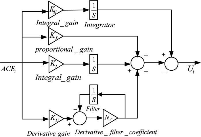
FIGURE 1. Controller structure for IPIDF.
In order to build controllers that use optimization techniques and to fine-tune controller parameters in accordance with performance indices, objective functions are used. Control designs often employ one of four basic types of objective functions (Shabani et al., 2013). The target function ITAE is used in this paper because it shortens peak overshoot and settling rate. It cannot be done using IAE or ISE-based correction, though. The mathematical formulas for the ITAE are shown in Eq. 2 (Sahu et al., 2016).
3 Differential evolution
The Differential Evolution (DE) algorithm, a straightforward, effective, and dependable heuristic search technique with minimal coding, was first introduced by Storn and Price (Stron and Prince, 1995). The Genetic Algorithm (GA) employs crossover operator for evolution based on the difference of randomly picked pairs of solutions in the population, whereas DE uses mutation operation, making it more favorable than GA. The DE algorithm employs two Generation, one of which is the old generation and the other is the new generation, both of which have the same population size and are controlled by the parameter Np, which is initialized at random (Pang et al., 2022) within the parameter constraints. A D-dimensional vector can serve as a representation for the D variables in an optimization job. Three key procedures are used to carry out the optimization process: mutation, crossover, and selection (Pant et al., 2020).
The target vectors for the following generation are people in the existing population (Sahu et al., 2016). Old and fresh generations of the same population size are used in the DE method. The present population’s individuals become the target vectors for the following generation. By adding the weighted difference between two randomly selected vectors to a third vector, the mutation process creates a mutant vector for each target vector. By combining the properties of the mutant vector and those of the target vector, the crossover procedure creates a trial vector. If the trial vector achieves a higher fitness value than the target vector, it replaces the target vector in the following generation. The flow chart of the DE algorithm is shown in Figure 2.
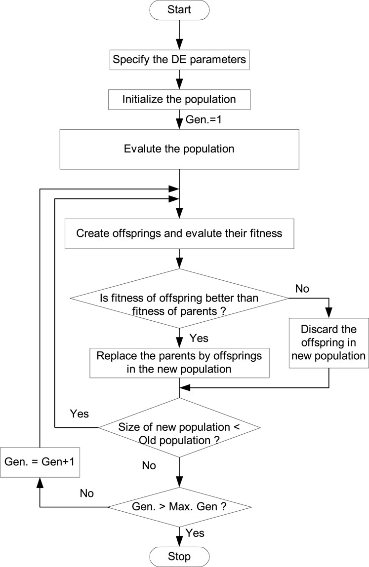
FIGURE 2. Flow chart of DE optimization approach.
4 Findings and discussion
4.1 Execution of DE
The MATLAB/SIMULINK environment was used to create the model of the system under study depicted in Figure 3 and a DE program was constructed (. mfile). The present work chooses −2.0 and 2.0 as the lowest and maximum values for controller parameters. The objective function, which is computed in the. m file, is used by the optimization process. In the current study, the population size NP = 100, generation number G = 100, step size F = .8, and crossover probability CR = .8 have all been used. With a situation of a 10% shift in the burden in Area-1 only at t = 0 s, the output/gain of the controller are optimized here by the DE method, and their control parameters are displayed in Table 1. The final value that is determined by repeating the optimization procedure 50 times will be determined by the optimal value for each parameter.
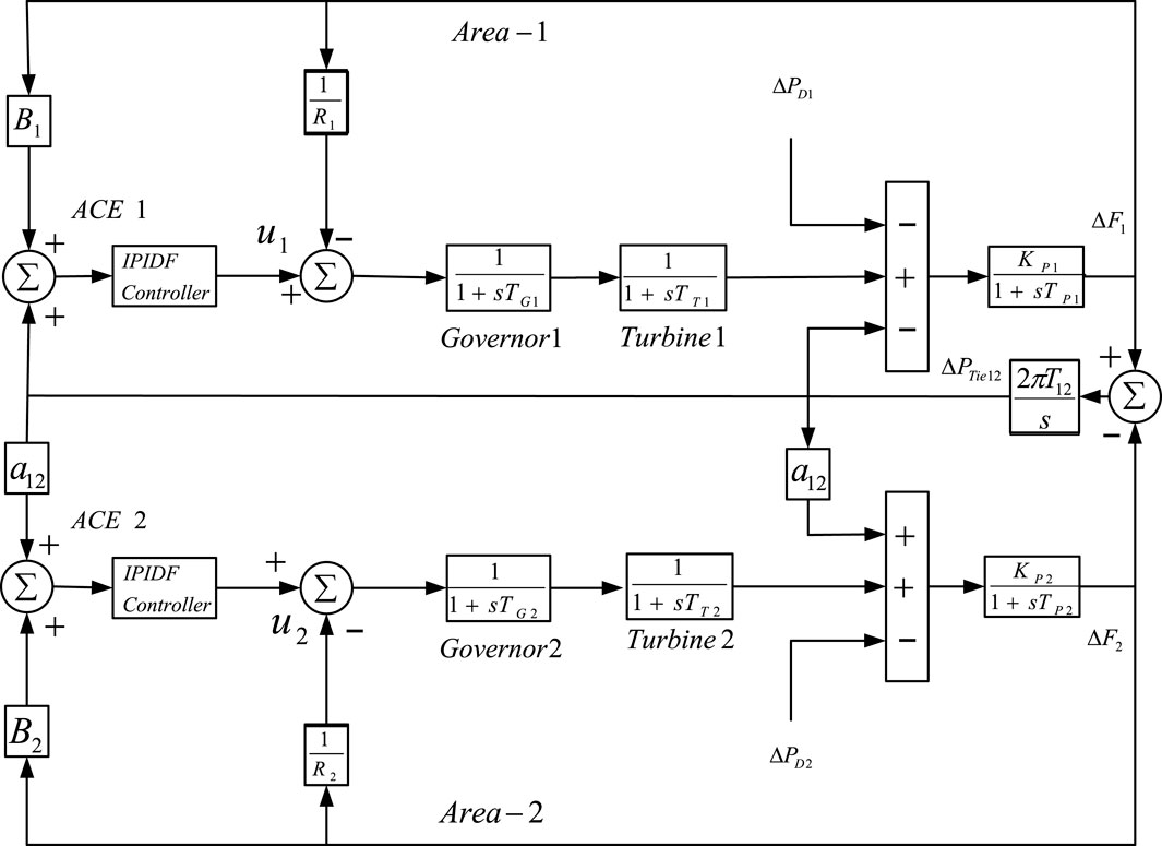
FIGURE 3. MATLAB/SIMULINK model interconnected power system.
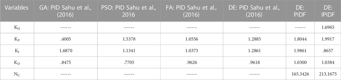
TABLE 1. Optimized IPIDF gain parameters for two-area thermal power system.
4.2 Analysis of results
Three examples can be taken into account in order to examine the dynamic performance of the system under examination. In the first scenario, Area-1 is the only one to receive the 10% step load; in the second, Area -2 is the only one to receive the 10% load disturbance; and, in the third scenario, Area -1 and Area -2, respectively, are the recipients of 10% and 20% step load. The effectiveness indicator values are given in Table 2 for the first case, where a 10% shift in the burden is applied to Area -1 at time t = 0 s. Figure 4 displays the associated frequency change in the area and Power variations along the tie line. In contrast to GA PID (Sahu et al., 2016), PSO PID (Sahu et al., 2016), FA PID (Sahu et al., 2016), DE: PID (.3391) (Sahu et al., 2016), and DE: PIDF (.1764), the IPIDF controller yields a reduced ITAE (.1238). When compared to other controllers, the proposed IPIDF controller reduces the ITAE value by 12.38%. The change in error is then displayed in Figure 5 when a similar operation is carried out with a 10% shift in the burden in Area -2 only at t = 0 s. Finally, Area -1 and Area -2, respectively, receive 10% and 20% step disruption. In Figure 6, the dynamic reaction is displayed. The figure clearly shows that the IPIDF controller functions more effectively analyzing peak overshoot and undershoot, as well as settling time. The yielded results of the IPIDF controller are therefore evidently better than that of the PIDF controller.
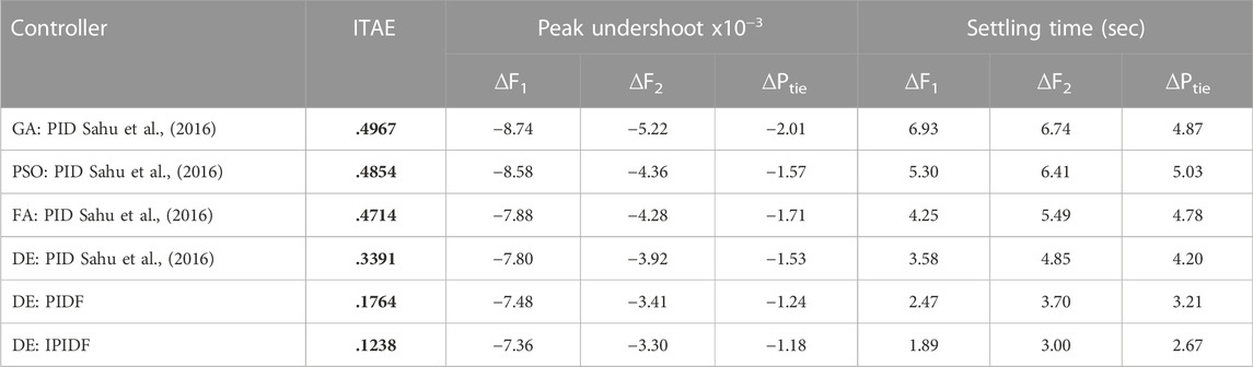
TABLE 2. Values of the Comparative Performance Index while region 1 is under 10% load.
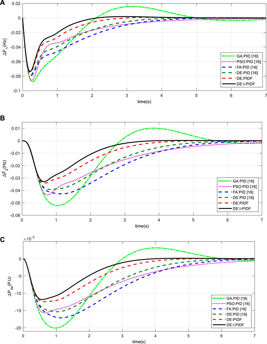
FIGURE 4. System dynamic responses for 10% shift in the burden in Area -1 only (A) frequency shift in Area 1 (B) frequency shift in Area 2 (C) power change in tie-line.
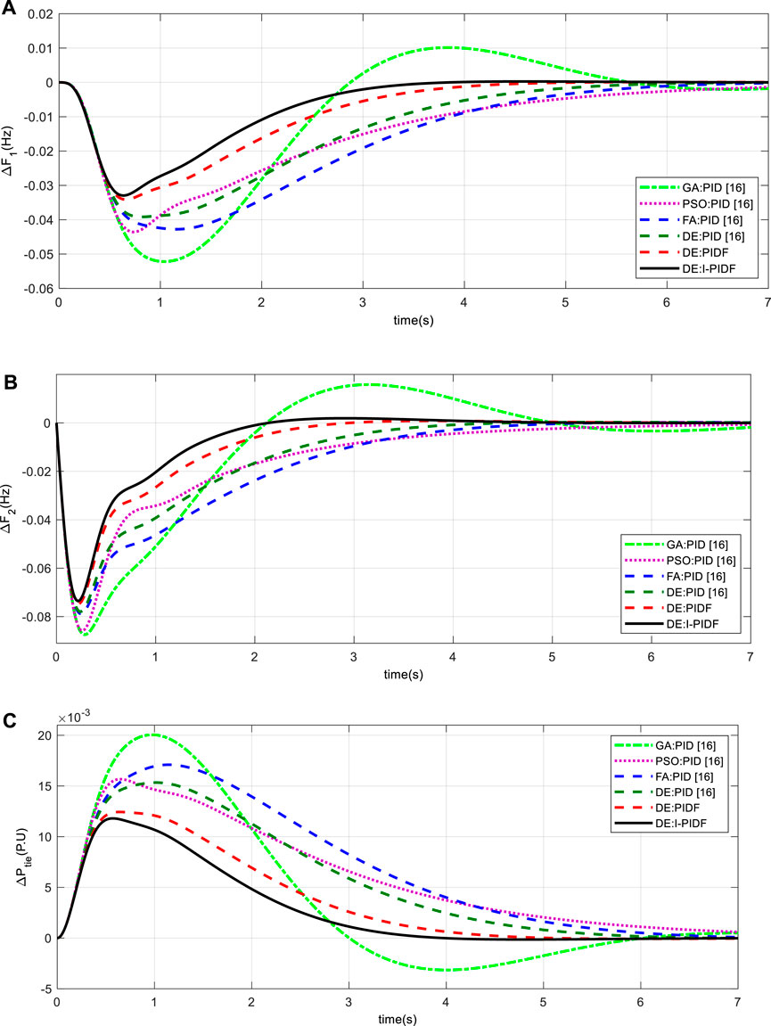
FIGURE 5. System dynamic responses for 10% shift in the burden in Area-2 only (A) frequency shift in Area 1 (B) frequency shift in Area 2 (C) power change in tie-line.
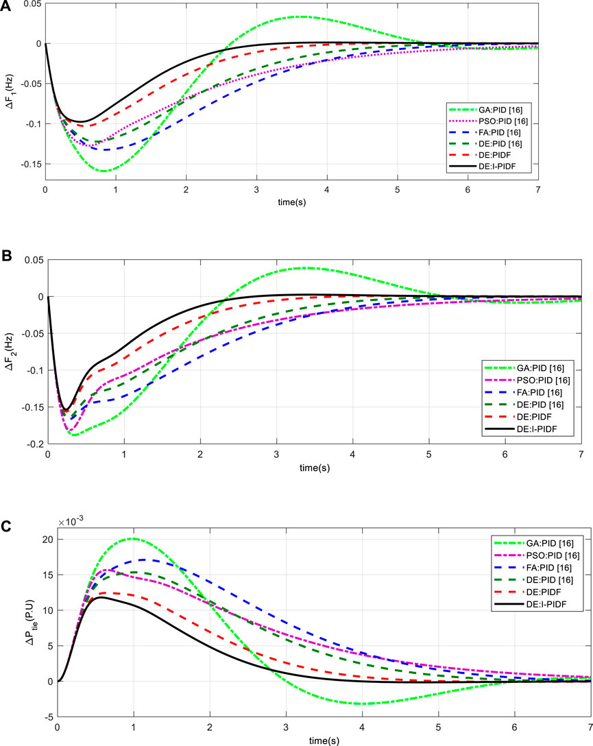
FIGURE 6. System dynamic responses for 10% shift in the burden in Area-1 and 20% in Area 2 (A) frequency shift in Area 1 (B) frequency shift in Area 2 (C) power change in tie-line.
4.3 Sensitivity analysis
Changes to the system’s operating circumstances and system parameters are made as part of the sensitivity study, which examines the proposed system’s resilience (Ali and Abd-Elazim, 2011; Panda et al., 2013; Padhan et al., 2014b; Sahu et al., 2016). Here, the reliability of the system is evaluated by altering the value of TG, TT, T12, and B in the range of ±25% for the same controller value. Here, under changing load conditions, a sensitivity study is conducted for 10% and 20% shift in burden in Area 1 and Area 2 respectively. Table 3’s listing of the system characteristics demonstrates how the IPIDF controller is resistant to various parameter variations.
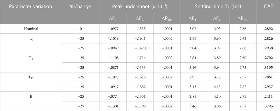
TABLE 3. Sensitive investigation using IPIDF controllers under various conditions of TG, TT, T12, and B.
5 Investigation with SMES and HVDC link
5.1 Modelling of SMES
The SMES’s capacity to store electrical energy in the form of magnetic energy and its ability to deliver enormous amounts of power instantly are two of its key capabilities. Because all of a SMES unit’s components are static, it is more stable than other power storage devices. Pradhan et al. (2016); model the SMES and connect in the power system to investigate the system. The model for SMES is shown in Figure 7. Two SMES units are set up in areas 1 and 2 in the current study to stabilize frequency oscillations, as depicted in Figure 9. The input signal of the SMES controller is p.u. frequency deviation (ΔF) and the output is change in control vector (ΔPSMES). The values of the time constant TSMES and the controller gains KSMES are .03 s and .12, respectively.
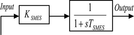
FIGURE 7. Structure of SMES.
5.2 Modelling of HVDC
A HVDC link is taken into consideration in parallel with the HVAC system in order to enhance the dynamic performance of the power system. Figure 8 depicts the single line diagram of a two-area power system with parallel HVAC/HVDC linkages. The HVDC link’s control system responds promptly to a step load disruption by suppressing the peak value of the transient frequency deviation. The governors then eliminate the steady state inaccuracies of the frequency deviation. The dynamics of the governors in both areas can be ignored for the purpose of simplicity in the control design of the HVDC link. The change in output in area-1 of an HVDC link can be expressed as follows for a sudden step load perturbation:
Where KDC is gain of a HVDC link and TDC is time constant of HVDC link in seconds.
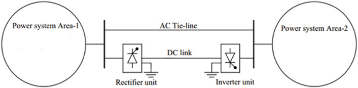
FIGURE 8. Two-area interconnected power system with HVDC.
5.3 Two area units non-reheat thermal power system with SMES and HVDC link
To demonstrate the efficacy of the suggested IPIDF controller, the study is further extended with SMES and HVDC link (Pradhan et al., 2016; Dekaraja et al., 2022; Ramoji, 2022; Sivadanam et al., 2022) as shown in Figure 9. The MATLAB/SIMULINK environment was used to create the model of the system under study depicted in Figure 9, and a DE program was constructed (. mfile). The present work chooses −2.0 and 2.0 as the lowest and maximum values for controller parameter for KII, KP, KI, and KD. The lowest and maximum value for the filer (NC) is taken 1 and 300 respectively. With a situation of a 10% shift in the burden in Area -1 only at t = 0 s, the output/gain of the controller are optimized here by the DE method. The same DE method, where the 50 best final solutions from the 50 optimization runs were utilized to establish the controller’s settings. The top 50 concluding responses from the 50 runs are shown in Table 4.
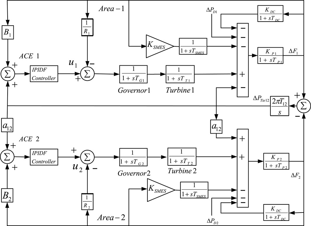
FIGURE 9. Thermal power system with SMES and HVDC Link MATLAB/SIMULINK model.
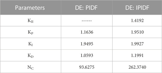
TABLE 4. Tuned IPIDF controller parameters with SMES and HVDC Link.
5.4 Analysis of the findings
Table 5 shows the outcome of the system DE-optimized IPIDF controller for the fast scenario, where Area -1 is subjected to a burden of 10% load at time t = 0 s. Performance of the proposed IPIDF controller is compared to that of PIDF. Table 5 makes it very evident that the IPIDF controller produces a lower ITAE value than the PIDF (ITAE = .3279 vs. .1330). Area -2 is the only location in the second scenario to have a burden of 10%. Finally, to investigate the dynamic performance of system 10% and 20% shift in burden is given to Area -1 and Area -2 accordingly. The dynamic reaction is seen in Figure 10–12. It is obvious that, in terms of output performance, the IPIDF controller surpasses the PIDF controller (minimal Peak undershoot, frequency settling durations, and power variations in tie-line).
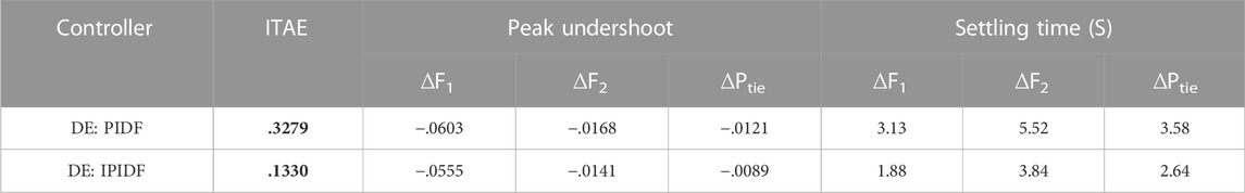
TABLE 5. Performance index values with SMES and HVDC Link.
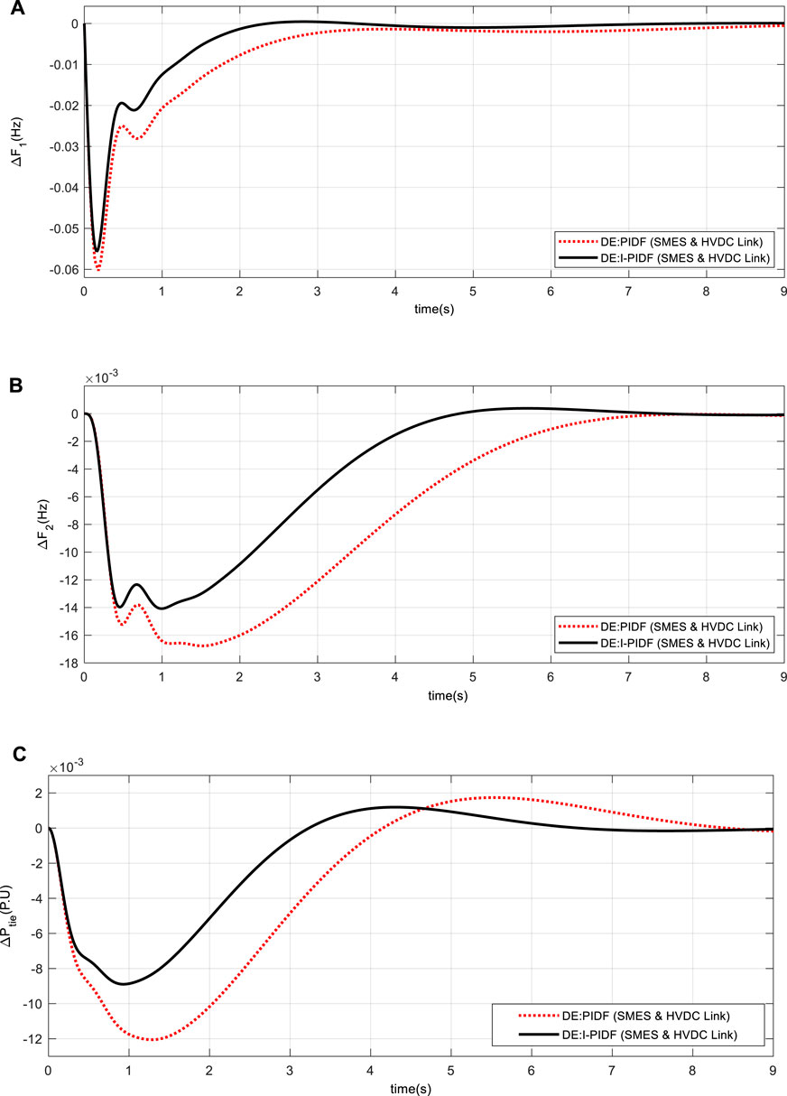
FIGURE 10. System dynamic responses for 10% shift in the burden in Area -1 only (A) frequency shift in Area 1 (B) frequency shift in Area 2 (C) power change in tie-line.
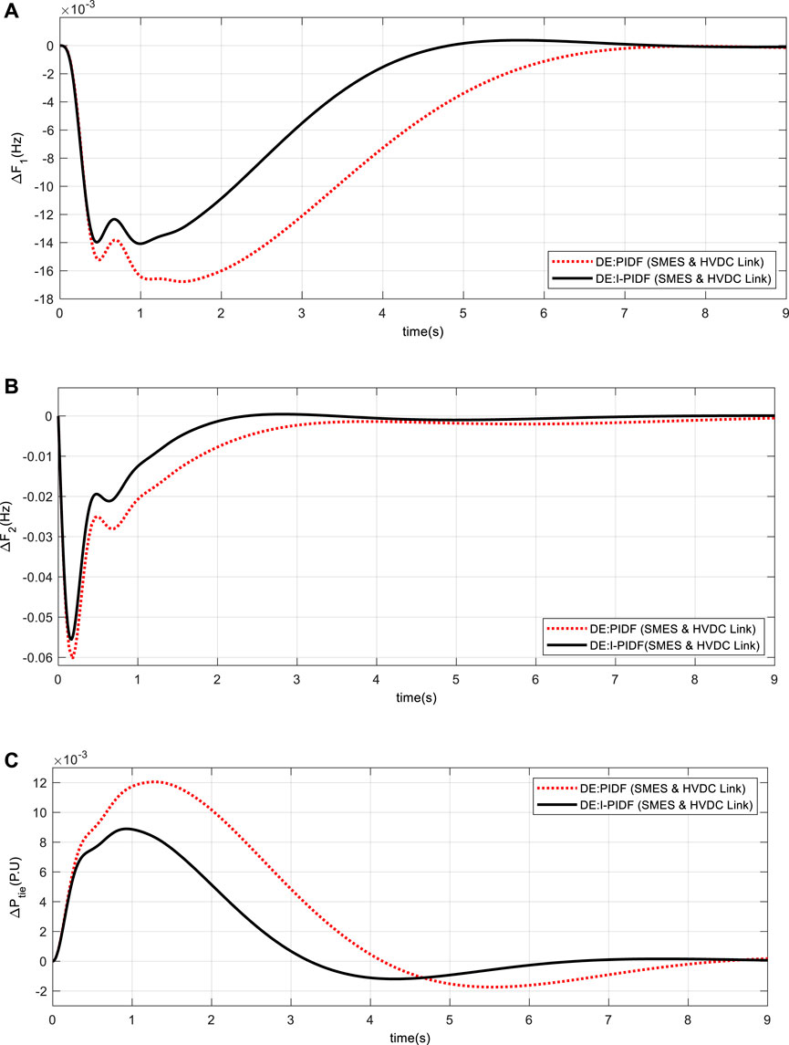
FIGURE 11. System dynamic responses for 10% shift in the burden in Area -2 only (A) frequency shift in Area 1 (B) frequency shift in Area 2 (C) power change in tie-line.
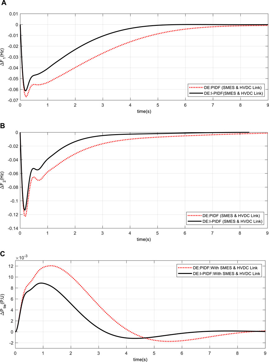
FIGURE 12. System dynamic responses for 10% shift in the burden in Area -1 and 20% in Area 2 (A) frequency shift in Area 1 (B) frequency shift in Area 2 (C) power change in tie-line.
Individual system performance of the system with just SMES and only HVDC connection is compared to the system with both SMES and HVDC link in order to demonstrate the effectiveness of adding both SMES and HVDC link to the systems. The change in errors for the 10% and 20% loads to Areas 1 and 2 is presented in Figure 13. From Figure 13, it is evident that the system clearly performs better when SMES and HVDC links are included in the system.
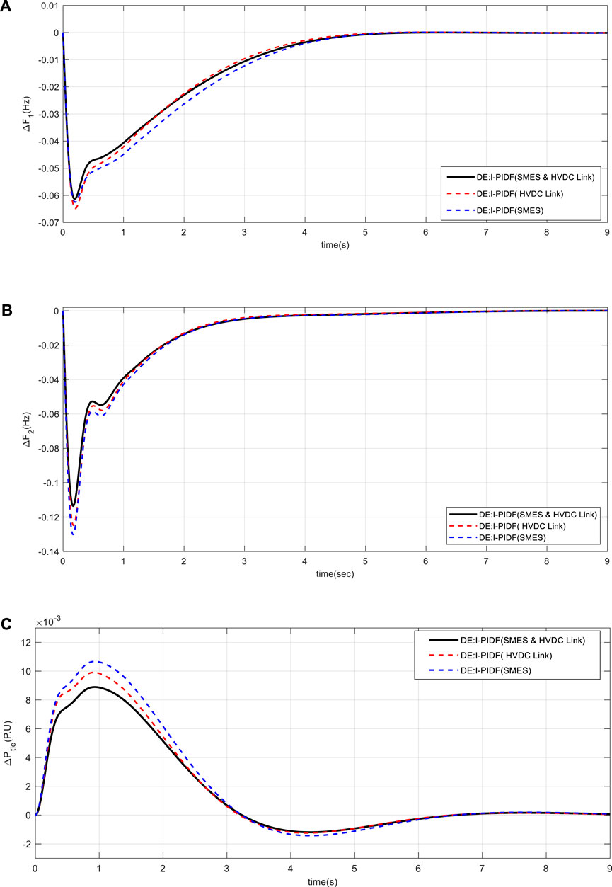
FIGURE 13. System dynamic responses for 10% shift in the burden in Area -1 and 20% in Area 2 (A) frequency shift in Area 1 (B) frequency shift in Area 2 (C) power change in tie-line.
5.5 Sensitivity analysis
The reliability of the system (Figure 9) is evaluated by altering the value of TG, TT, T12, and B in the range of ±25% for the same controller value. Here, under changing load conditions, a sensitivity study is conducted for 10% shift in burden in Area 1 only. Table 6’s listing of the system characteristics demonstrates how the IPIDF controller is resistant to various parameter variations. Table 6 makes it evident that the performance index values fluctuate within allowable limits and are typically identical to the standard value. Dynamic nature of the system for different parameter variation is shown in Figure 14.
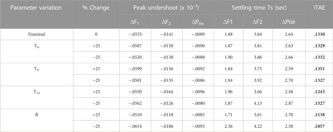
TABLE 6. Sensitive analysis with IPIDF controllers when TG, TT, T12 and B are varied.
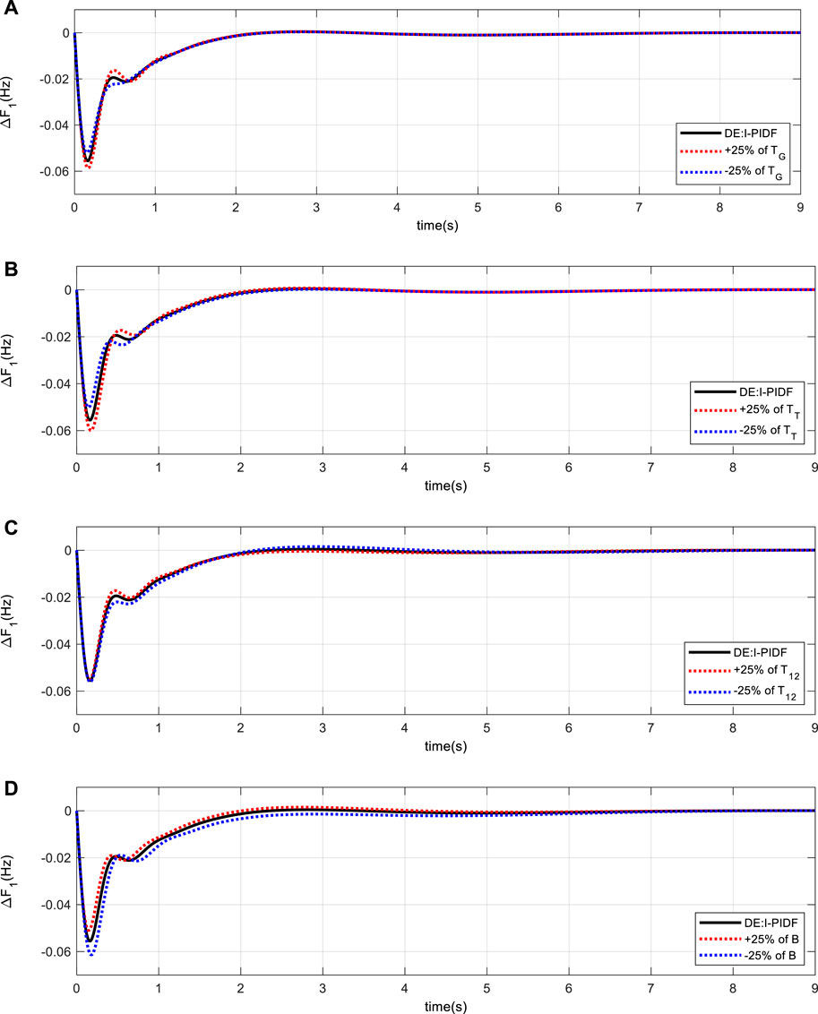
FIGURE 14. Area-1 frequency variation with .1 p.u. of load with variation of (A) TG (B) TT (C) T12 (D) B.
5.6 Assessment of the effectiveness under various load disturbance scenarios
A performance analysis of the suggested system is also done for several load perturbations, such as step load and pulse load to Area 1 (Sahu et al., 2016). Figure 15A depicts the application of a step load to region 1 that has a period of 140 s and a breadth of 10 s (Sahu et al., 2016). Figure 15B depicts the corresponding tie-line power exchange. Area 1 is then put under a pulse (Sahu et al., 2016) change with an initial magnitude of 10% P.U and a frequency of .025 Hz shown in Figure 16A. Figure 16B depicts the change in tie-line power. We can infer from all of the findings that the IPIDF controller reduces oscillation.
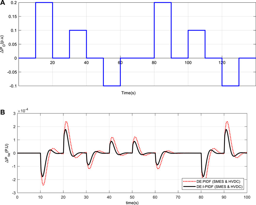
FIGURE 15. (A) Random step load (B) tie-line power deviation between area 1 and area 2.
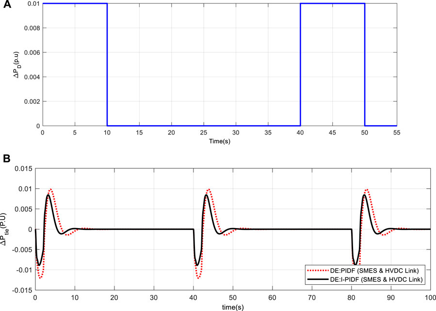
FIGURE 16. (A) Pulse load (B) tie-line power deviation between area 1 and area 2.
6 Conclusion
This work has addressed the Load Frequency Control (LFC) of a two-area linked system using a special IPIDF controller. The Differential Evolution approach was employed to improve the IPIDF controller’s settings with an ITAE-based fitness function. By comparing the outcomes with those of other recently published optimization approaches, such as Particle Swarm Optimization (PSO), Firefly Algorithm (FA), and Differential Evolution (DE) algorithm based PID and PIDF controllers, the supremacy of the IPIDF controller is shown. A two-area system that takes into consideration both a HVDC connection and a superconducting magnetic energy storage device is added to the recommended method. There have been reports of considerable improvements in dynamic responsiveness when the IPIDF controller is used in conjunction with superconducting magnetic energy storage and an HVDC link. Additionally, a sensitivity study of the operational state and system parameters in the range of +25 to -25% from their nominal values is conducted to evaluate the system’s resilience. Next, the efficacy of the presented method is reviewed under several load perturbations, such as step load and pulse load. The results demonstrate that the created controller is trustworthy and perform admirably under a variety of operating circumstances, system characteristics, and load patterns.
Data availability statement
The original contributions presented in the study are included in the article/supplementary material, further inquiries can be directed to the corresponding author.
Author contributions
All authors listed have made a substantial, direct, and intellectual contribution to the work and approved it for publication.
Conflict of interest
The authors declare that the research was conducted in the absence of any commercial or financial relationships that could be construed as a potential conflict of interest.
The handling editor declared a shared affiliation with the reviewer SP at the time of the review.
Publisher’s note
All claims expressed in this article are solely those of the authors and do not necessarily represent those of their affiliated organizations, or those of the publisher, the editors and the reviewers. Any product that may be evaluated in this article, or claim that may be made by its manufacturer, is not guaranteed or endorsed by the publisher.
References
Ahmed, M., Magdy, G., Khamies, M., and Kamel, S. (2022). Modified TID controller for load frequency control of a two-area interconnected diverse-unit power system. Int. J. Electr. Power & Energy Syst. 135, 107528. doi:10.1016/j.ijepes.2021.107528
Ali, E. S., and Abd-Elazim, S. M. (2011). Bacteria foraging optimization algorithm-based load frequency controller for interconnected power system. Int. J. Electr. Power Energy Syst. 33, 633–638. doi:10.1016/j.ijepes.2010.12.022
Banerjee, S., Chatterjee, J. K., and Tripathy, S. C. (1990). Application of magnetic energy storage unit as load-frequency stabilizer. Trans. Energy Conv. 5, 46–51. doi:10.1109/60.50811
Dekaraja, B., and Chandra Saikia, L. (2022). Impact of energy storage and flexible alternating current transmission devices in combined voltage and frequency regulation of multiarea Multisource Interconnected Power System. Energy Storage 4, e317. doi:10.1002/est2.317
Dekaraja, B., Saikia, L. C., Ramoji, S. K., Behera, M. K., and Bhagat, S. K. (2022). Performance analysis of diverse energy storage on combined ALFC and AVR control of multiarea multiunit system with AC/HVDC interconnection. IFAC-Papers Line 551, 479–485. doi:10.1016/j.ifacol.2022.04.079
El-Ela, A. A. A., El-Sehiemy, R. A., Shaheen, A. M., and Diab, A. E. G. (2022). Design of cascaded controller based on coyote optimizer for load frequency control in multi-area power systems with renewable sources. Control Eng. Pract. 121, 105058. doi:10.1016/j.conengprac.2021.105058
Elgerd, O. I. (2000). Electric energy systems theory (2000) – an introduction. New Delhi: Tata McGraw Hill.
Karn, A. K., Hameed, S., Sarfraz, M., Ro, J. S., and Khalid, M. R. (2022). Load shedding for frequency and voltage control in the multimachine system using a heuristic knowledge discovery method. Front. ENERGY Res. 10. doi:10.3389/fenrg.2022.1002064
Luo, K., Jiao, Y., and Zhu, J. (2021). Perturbation observer based fractional-order control for SMES systems based on jellyfish search algorithm. Front. Energy Res. 695. doi:10.3389/fenrg.2021.781774
Padhan, S., Sahu, R. K., and Panda, S. (2014). Application of Firefly algorithm for load frequency control of multi-area interconnected power system. Electr. Power Compon. Syst. 42, 1419–1430. doi:10.1080/15325008.2014.933372
Padhan, S., Sahu, R. K., and Panda, S. (2014). Automatic generation control with thyristor-controlled series compensator including superconducting magnetic energy storage units. Ain Shams Eng. J. 5 (3), 759–774. doi:10.1016/j.asej.2014.03.011
Panda, S., Mohanty, B., and Hota, P. K. (2013). Hybrid BFOA–PSO algorithm for automatic generation control of linear and nonlinear interconnected power systems. Soft Comput. 13 (12), 4718–4730. doi:10.1016/j.asoc.2013.07.021
Pang, S., Liu, J., Zhang, Z., Fan, X., Zhang, Y., Zhang, D., et al. (2022). A photovoltaic power predicting model using the differential evolution algorithm and multi-task learning. Front. Mater. 9, 938167. doi:10.3389/fmats.2022.93816
Pant, M., Zaheer, H., Garcia-Hernandez, L., and Abraham, A. (2020). Differential evolution: A review of more than two decades of research. Eng. Appl. Artif. Intell. 90, 103479. doi:10.1016/j.engappai.2020.103479
Peng, Bo (2022). Coordinated AGC control strategy for an interconnected multi-source power system based on distributed model predictive control algorithm. Front. Energy Res. 1678.
Pradhan, P. C., Sahu, R. K., and Panda, S. (2016). Firefly algorithm optimized fuzzy PID controller for AGC of multi-area multi-source power systems with UPFC and SMES. Int. J. 19, 338–354. doi:10.1016/j.jestch.2015.08.007
Ram Babu, N., and Saikia, L. C. (2021). Load frequency control of a multi-area system incorporating realistic high-voltage direct current and dish-Stirling solar thermal system models under deregulated scenario. IET RPG 15 (5), 1116–1132. doi:10.1049/rpg2.12093
Ramoji, S. K. (2022). “Repercussions of SMES and HVDC link in amalgamated voltage and frequency regulation of multi-area multi-unit interconnected power system,” in 2022 4th International Conference on Energy, Power and Environment (ICEPE), Shillong, India, 29 April 2022-01 May 2022.
Sahu, R. K., Panda, S., Biswal, A., and Chandra Sekhar, G. T. (2016). Design and analysis of tilt integral derivative controller with filter for load frequency control of multi-area interconnected power systems. ISA Trans. 61, 251–264. doi:10.1016/j.isatra.2015.12.001
Shabani, H., Vahidi, B., and Ebrahimpour, M. (2013). A robust PID controller based on imperialist competitive algorithm for load-frequency control of power systems. Trans 52, 88–95. doi:10.1016/j.isatra.2012.09.008
Sivadanam, N., Bhookya, N., and Maheswarapu, S. (2022). Stochastic and iterative based optimization for enhancing dynamic performance of interconnected power system with hybrid energy storage. Front. Energy Res. 10, 175. doi:10.3389/fenrg.2022.845686
Soni, V., Parmar, G., and Kumar, M. (2021). A hybrid grey wolf optimisation and pattern search algorithm for automatic generation control of multi-area interconnected power systems. Int. J. Adv. Intell. Paradig. 18 (3), 265. doi:10.1504/IJAIP.2021.10035674
Stron, R., and Prince, K. (1995). Differential evolution- a simple and efficient adaptive scheme for global optimization over continuous spaces. J. Glob. Optim. 11, 341–359. doi:10.1023/A:1008202821328
Sudha, K. R., and Vijaya, S. R. (2012). Load frequency control of an interconnected reheat thermal system using type-2 fuzzy system including SMES units” Int. J. Elec. Power Energy Syst. 43, 1383–1392.
Sun, Y., and Duan, W. (2022). Stability analysis of load frequency control for power systems with interval time-varying delays. Front. Energy Res. 1507.
Wang, X., Gu, L., and Liang, D. (2021). Decentralized and multi-objective coordinated optimization of hybrid AC/DC flexible distribution networks. Front. Energy Res. 9, 646. doi:10.3389/fenrg.2021.762423
Yang, C., Sun, W., Dong, H., and Yin, X. (2022). Research on power system flexibility considering uncertainties. Front. Energy Res. 1343. doi:10.3389/fenrg.2022.967220
Nomenclature
f nominal system frequency (Hz)
u controller Output
ACE Area Control Error
KSMES gain of the SMES
KDC gain of a HVDC link
i subscript referred to area i (1–2)
ΔPSMES output signal of SMES
TSMES time constant of the SMES
TDC time constant of HVDC link in sec
Appendix
The system being studied has the following nominal parameters: (Padhan et al., 2014a; Sahu et al., 2016; Luo et al., 2021).
Keywords: load frequency control (LFC), differential evolution (DE) algorithm, proportional integral derivative (PID), integral plus proportional integral derivative controller with filter (IPIDF), superconducting magnetic energy storage system (SMES)
Citation: Biswal A, Dwivedi P and Bose S (2022) DE optimized IPIDF controller for management frequency in a networked power system with SMES and HVDC link. Front. Energy Res. 10:1102898. doi: 10.3389/fenrg.2022.1102898
Received: 19 November 2022; Accepted: 12 December 2022;
Published: 23 December 2022.
Edited by:
Sarat Kumar Sahoo, Parala Maharaja Engineering College (P.M.E.C), IndiaReviewed by:
Balamurugan M, Dayananda Sagar College of Engineering, IndiaSaroj Padhan, Parala Maharaja Engineering College (P.M.E.C), India
Saravanan B, VIT University, India
Copyright © 2022 Biswal, Dwivedi and Bose. This is an open-access article distributed under the terms of the Creative Commons Attribution License (CC BY). The use, distribution or reproduction in other forums is permitted, provided the original author(s) and the copyright owner(s) are credited and that the original publication in this journal is cited, in accordance with accepted academic practice. No use, distribution or reproduction is permitted which does not comply with these terms.
*Correspondence: Ashutosh Biswal, bGlua3UuYXNodXRvc2hAZ21haWwuY29t