Abstract
With the gradual increase in the penetration rate of distributed power sources, in view of the planning problem of coordinating the location and capacity of distributed power sources with the grid frame and transformers of the distribution network, a distribution network that takes into account distributed power sources is proposed. Aiming at the lowest cost of investment, maintenance, energy production, energy loss, and load loss penalty, and considering the power flow constraints, planning and operation constraints of each planning stage, a multi-stage expansion planning model for the distribution network is established. The mixed-integer linear programming algorithm is used to solve the problem, and the optimal planning scheme at each stage is obtained. The simulation results show that the multi-stage expansion planning method for coordinating distributed power and distribution network proposed in this paper can prevent the problems of isolated nodes and transmission nodes, improve the reliability of the planning scheme, and have good economic benefits.
1 Introduction
With the deterioration of the environment and the continuous change of the energy structure (National Development and Reform Commission, 2015; Mansor and Levi, 2018; Nikoobakht et al., 2020), the penetration of Distributed Generation (DG) is gradually increasing (Afraz et al., 2019; Borghei and Ghassemi, 2021). This means that the distribution network structure as well as the power supply mode has changed (Alarcon et al., 2020; Vahidinasab et al., 2020). On the one hand, the planning results of distributed power supply and distribution network will affect each other, and it is difficult to achieve the overall optimum for a single separate planning. This will affect the planning economy and reliability (Cattani et al., 2020; Shahbazi et al., 2021a). On the other hand, for medium-term and long-term distribution network planning, its construction works are often divided into multiple stages, which are reasonably adjusted according to the changes in load. A single-stage planning model makes it difficult to take into account future load changes and the impact of distributed power sources (Franco, 2016). Therefore, it is necessary to coordinate and unify the siting and capacity of distributed power with the planning of the distribution network’s grid and transformers. And it is important to study a multi-stage coordinated planning method of distribution network taking into account distributed power sources.
There are a lot of research on distribution network planning problems (Saeed and Mahmud, 2018; Koutsoukis and Georgilakis, 2019; Faria et al., 2020; Delarestaghi et al., 2021; Mojtahedzadeh et al., 2021). The author in Liu et al. (2019) takes into account the volatility of DG output and establishes a DG siting and capacity model with the minimum risk of distribution network operation as the objective function. Narimani et al. (2018) use Monte Carlo for simulation and introduces delayed option theory for planning the multiple uncertainties of load as well as tariff in incremental distribution network planning. Jooshaki et al. (2020) considers the impact of DG on the distribution network grid structure and optimizes the lines, DG locations, and capacity of the distribution network in the distribution network planning process, but ignores the coordination between DG and the distribution network. In response to the above problems, Akbari and Moghaddam (2020) proposes to construct a fuzzy planning of distribution network grid considering DG output uncertainty. It coordinates the interaction between DG and the distribution network grid. Hemmati et al. (2015) considers the uncertainty of load and price in the electricity market environment. In the paper, a coordination and expansion planning model of distribution network and DG is proposed and the model is solved by particle swarm optimization algorithm. Muoz -Delgado et al. (2014) considered several alternatives for the installation or replacement of DGs, feeders, and transformers, and proposed a joint expansion planning model for DGs and distribution networks. The results show that incorporating distributed generation investments into the distribution network problem can significantly reduce investment costs. However, these models involve only one planning phase. In the actual planning process, construction projects are often divided into multiple stages. If a single-stage planning model is used, it is difficult to take into account future load changes and the impact of distributed power sources, and lacks an integrated layout for long-term investment strategies.
To address the multi-stage planning problem, the Tabares et al. (2015); Xing et al. (2016) considered line, substation, and distributed power supply renewal replacement and proposed a multi-stage planning model of distribution network with mixed integer linear programming. However, relatively little attention has been paid to the issue of joint expansion. The author in Masoumi-Amiri et al. (2021) propose a multi-stage planning model for active distribution networks considering the load level by using a clustering algorithm for multi-stage division of the source-load timing characteristics. And it increases the penetration of distributed power and the reliability of the system. Xiao et al. (2020) proposes an active distribution network multi-stage two-level planning model. The paper presents the boundary conditions for the most multi-stage planning with operationally constrained cases. The model improves the economics of the investment as well as the reliability of the actual operation. Shahbazi et al. (2021b) use the idea of multi-stage planning for the siting of distributed power sources and distribution grids and for the expansion of the grid. The paper improves the convergence speed of model solving by using the improved genetic membrane algorithm. However, it ignores the expansion decision of distributed generation and focuses the study on the impact of distributed power expansion on distribution investment deferral instead of solving the optimization problem of the joint expansion planning model.
To address the problems of existing research, this paper proposes a multi-stage planning method for distribution networks that considers distributed power sources. This paper establishes a multi-stage expansion planning model for distribution networks. The model aims to minimize the cost of investment, maintenance, energy production, energy loss and loss of load penalties and consider the tidal constraints, planning and operational constraints for each planning stage. The model is solved using a mixed integer linear programming algorithm to obtain the optimal planning solution for each stage. At the end of the article, the economics and effectiveness of the proposed method are verified by simulation examples.
2 Distribution Network Coordination Planning Model
2.1 Objective Function
The distribution network planning model aims at minimizing the total cost F. The objective function mainly includes investment cost , maintenance cost , production cost , energy loss cost and penalty cost . The details are as follows:Where, T is the set of planning stages; i is the annual interest rate; nT is the number of planning stages; is the investment cost; are the cost of energy production, maintenance, losses and penalties at stage t, respectively; are the cost of energy production, maintenance, losses and penalties for the time planning phase nT, respectively.
2.1.1 Investment Costs
Investment costs for all stages include replacement and new feeder costs, reinforcement of existing substations and new substation costs, new transformer costs, and distributed power costs. The formula is shown below:Where, are the set of new feeders, transformers and distributed power sources that can be constructed, respectively; are collection of substations and distributed power supplies; is the set of feeder types l, where feeder type L: represent existing feeders, replaceable feeders, new replaceable feeders and new feeders; are the investment cost factors for feeders, substations, transformers and distributed power sources, respectively; is the length of the feeder sr; are 0–1 variables and it is used to indicate whether decision feeders, substations, transformers and distributed power supplies are constructed; is the system power factor; is the rated capacity of generator k.
2.1.2 Maintenance Costs
Maintenance costs in all stages include feeder, transformer and generator maintenance costs. This is shown in Equation 3Where, is the transformer type, where represent existing transformers and new transformers respectively; is the type of generator set, where represent conventional units and distributed wind turbines respectively; are the maintenance cost factors for feeders, generators and transformers; are 0–1 variables and these variables are used to make decisions about feeder, transformer and generator operating conditions.
2.1.3 Energy Production Costs
Energy production costs for each stage include energy production conversion costs for substations and distributed power sources and determined by Equation 4Where, is the set of load levels; is the duration of the load level b; are the cost coefficients of energy supply for substations and generating units; are the currents injected into node s by the transformer and generator set, respectively.
2.1.4 Energy Loss Costs
Energy loss costs include energy loss costs for transformers and feeders. The specific calculation of energy loss cost is shown in Equation 5Where, is the energy loss cost factor of the substation; are the impedance of the transformer and the unit impedance of the feeder; is the current injected into node s by the transformer; is the current in the feeder sr.
2.1.5 Penalty Costs
Penalty costs include those incurred by generators and substations when they fail to meet load demand. The penalty cost is calculated by Equation 6Where, is the penalty cost factor and is the unsatisfied load of node s.
2.2 Constraint Conditions
2.2.1 Flow Constraint
The flow constraint is used to constrain the operating state of the system to ensure the normal operation of the system, and the relevant constraint equation is as follows.
1) Node voltage constraints
Where, a is the voltage of node s at load level b in planning stage t; b, c are the minimum and maximum values of node voltage, respectively.
2) Feeder current constraints
Where,
is the maximum value of the current flowing through the feeder.
3) Transformer injection current constraints
Where,
is the maximum value of transformer current injection.
4) Loss of load constraints
Where,
is the load factor at load level
b;
is the maximum load demand at node
s.
5) Unit output constraints
Where,
is the maximum wind speed level.
6) Distributed power penetration constraints
Where,
is the upper limit of penetration of distributed generation.
7) Node current balance constraints
8) Feeder state constraints
Where,
are the voltage amplitudes at node s and node r, respectively.
2.2.2 Planning and Operational Constraints
In this paper, Eqs. 15–18 are line, substation, transformer, and distributed power supply construction constraints and these constructions allow up to one reinforcement, replacement or new construction; Eq. 19 is a new transformer constraint to ensure that new transformers can only be added to previously expanded or constructed substations; Eqs. 20–22 are the constraints on the use of the feeder, which determine the direction of the current; Eqs. 23, 24 are the new transformers and distributed generators put into operation constraints; Eq. 25 is the investment constraint for each stage. The construction program for each stage, the timing as well as the number of lines, substations, transformers, and distributed power sources shall meet the following constraints:Where, is the investment budget for stage t; is the set of feeder types l, where feeder type L: represent existing feeders, replaceable feeders, new replaceable feeders and new feeders; is the length of the feeder sr; are 0–1 variables and it is used to indicate whether decision feeders, substations, transformers and distributed power supplies are constructed.
3 Simulation and Analysis
3.1 Parameter Setting
In this paper, to verify the validity of the proposed methodology, a 3-year phase planning analysis is conducted using the IEEE 24-node power distribution system. The system includes 20 load nodes, 4 substation nodes and 33 feeders, and its topology is shown in Figure 1. Where the system voltage level is 20 KV, the upper and lower limits of the node voltage are 0.95–1.05pu of the rated voltage, and the inflation rate is 0.05; the load data for the three stages are shown in Table 1, with a load power factor of 0.9 and a load cutting cost of 16 yuan/kwh; line data as shown in Table 2, with a feeder life of 30 years; The wind speed data for each region in the three stages are shown in Table 3; the parameters related to the DG to be selected and the conventional unit are shown in Table 4, where the positions to be selected are {1, 4, 5, 9, 15, 17, 18, 19} for the DG and {2, 3, 7, 13, 15, 16, 17, 20} for the conventional unit; the parameters of the constructed and to-be-constructed substation are shown in Table 5, and the cost of purchasing power from the substation is 0.49 yuan/kwh; the relevant parameters of the conductor to be selected are shown in Table 6.
FIGURE 1
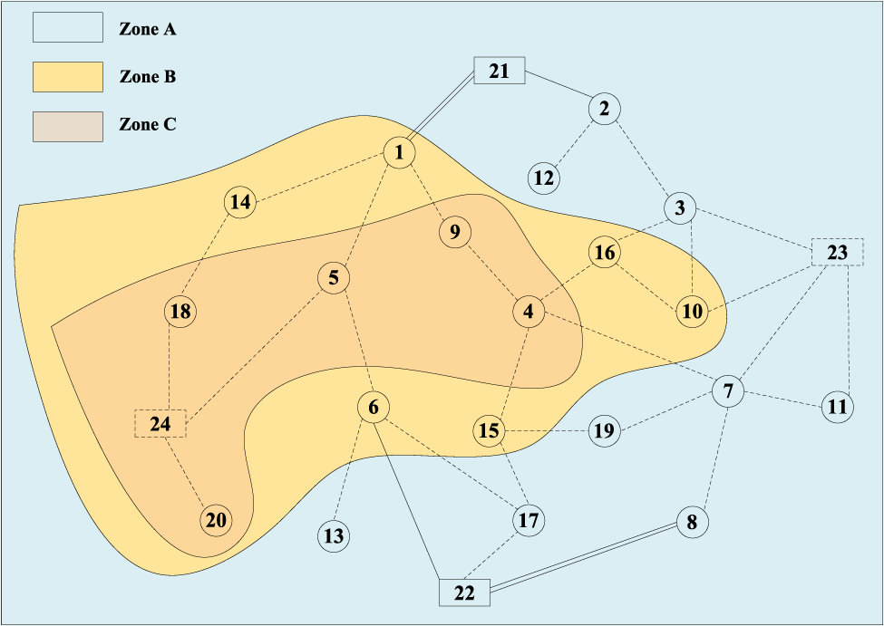
24 node distribution system.
TABLE 1
| Node | Stage/MVA | Node | Stage/MVA | ||||
|---|---|---|---|---|---|---|---|
| 1 | 2 | 3 | 1 | 2 | 3 | ||
| 1 | 5.13 | 4.21 | 6.24 | 11 | 0.00 | 1.53 | 2.64 |
| 2 | 0.58 | 0.45 | 1.21 | 12 | 0.00 | 0.96 | 1.36 |
| 3 | 2.65 | 3.74 | 4.21 | 13 | 0.00 | 1.14 | 1.87 |
| 4 | 0.38 | 0.51 | 2.54 | 14 | 0.00 | 3.09 | 3.15 |
| 5 | 0.21 | 0.36 | 0.46 | 15 | 0.00 | 1.63 | 1.62 |
| 6 | 1.42 | 0.69 | 1.81 | 16 | 0.00 | 2.17 | 1.24 |
| 7 | 4.32 | 3.74 | 4.36 | 17 | 0.00 | 0.00 | 2.48 |
| 8 | 0.74 | 0.63 | 0.96 | 18 | 0.00 | 0.00 | 2.17 |
| 9 | 1.32 | 1.24 | 1.74 | 19 | 0.00 | 0.00 | 1.82 |
| 10 | 1.52 | 2.31 | 2.41 | 20 | 0.00 | 0.00 | 3.74 |
Distribution network node load data.
TABLE 2
| Branch | lsr/km | Branch | lsr/km | Branch | lsr/km | |||
|---|---|---|---|---|---|---|---|---|
| s | r | s | r | s | r | |||
| 1 | 5 | 2.64 | 4 | 9 | 1.20 | 7 | 23 | 0.90 |
| 1 | 9 | 1.25 | 4 | 15 | 1.60 | 8 | 22 | 1.90 |
| 1 | 14 | 1.25 | 4 | 16 | 1.30 | 10 | 16 | 1.60 |
| 1 | 21 | 2.64 | 5 | 6 | 2.40 | 10 | 23 | 1.30 |
| 2 | 3 | 2.00 | 5 | 24 | 0.70 | 11 | 23 | 1.60 |
| 2 | 12 | 1.10 | 6 | 13 | 1.20 | 14 | 18 | 1.00 |
| 2 | 21 | 1.70 | 6 | 17 | 2.20 | 15 | 17 | 1.20 |
| 3 | 10 | 1.10 | 6 | 22 | 2.70 | 15 | 19 | 0.80 |
| 3 | 16 | 1.20 | 7 | 8 | 2.00 | 17 | 22 | 1.50 |
| 3 | 23 | 1.20 | 7 | 11 | 1.10 | 18 | 24 | 1.50 |
| 4 | 7 | 2.60 | 7 | 19 | 1.20 | 20 | 24 | 0.90 |
Branch data.
TABLE 3
| Zone | Wind speed/(m/s) | ||
|---|---|---|---|
| 1 | 2 | 3 | |
| A | 9.44 | 10.36 | 11.25 |
| B | 5.32 | 8.47 | 7.36 |
| C | 4.69 | 6.21 | 5.97 |
Wind speed for each area in the three stages.
TABLE 4
| Type | Capacity/MW | Construction costs/(million yuan/MW) | Maintenance costs/(yuan/MWh) | |
|---|---|---|---|---|
| Wind Turbines | 1 | 1 | 130 | 300 |
| 2 | 2 | 120 | 280 | |
| Conventional Units | 1 | 0.95 | 1120 | 50 |
| 2 | 2.25 | 1100 | 50 |
Related parameters of DG to be selected and conventional units.
TABLE 5
| Transformer type | Capacity/MW | Impedance/Ω | Investment costs/million yuan | Maintenance costs/yuan |
|---|---|---|---|---|
| 1 | 12 | 0.16 | 450 | 1200 |
| 2 | 15 | 0.13 | 600 | 1500 |
Related parameters for candidate transformers units.
TABLE 6
| Line type | Current limit/MVA | Impedance/(Ω/km) | Investment costs/(million yuan/km) | |
|---|---|---|---|---|
| NRF | 1 | 6.29 | 0.557 | 11.5 |
| 2 | 9.21 | 0.487 | 18.2 | |
| NAF | 1 | 3.96 | 0.731 | 9.1 |
| 2 | 6.29 | 0.558 | 15.3 |
Related parameters for candidate conductors units.
The simulation was performed in Win10 environment with Intel(R) Core(TM) i5-7200U CPU @ 2.50GHz, running memory of 8 GB, and simulation software of MATLAB R2016b. Since the model developed is an integer linear programming model, the YALMIP & CPLEX solver is used to solve the model. Two cases are set up for comparative analysis.
Case Idistribution network expansion planning without considering distributed power sources.
Case IIMulti-stage expansion planning of distribution network considering distributed power sources (method in this paper).
3.2 Analysis of Planning Results
As can be seen in Figure 2, the two cases have significantly different planning results at each planning stage. The capacity of the feeder and transformer installed without distributed power is greater than the capacity of the feeder and transformer installed with distributed power. It results in larger investment costs in feeders and transformers. In the case of distributed generation, the load pressure can be effectively relieved by installing wind turbines as the load demand gradually increases. On the other hand, more distributed power sources are installed in the C zone, where wind speeds are higher, and conventional generators are mostly installed at load nodes outside the C zone.
FIGURE 2
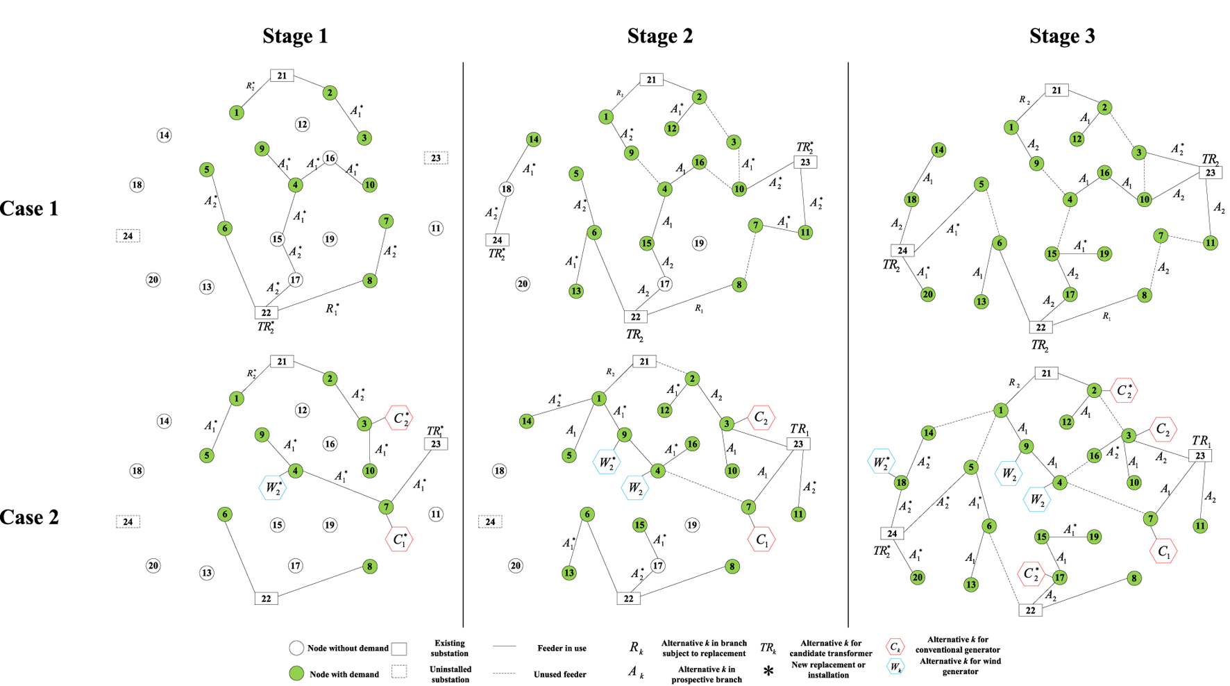
Planning schemes for two cases.
3.3 System Performance Comparison
The unit output as well as loss data for different cases are shown in Table 7. As can be seen in Table 7, the addition of distributed power sources leads to a significant reduction in the level of energy provided by the transformer located at the substation node. In addition, for Case 2, the energy losses in the feeder and transformer are lower than those in Case 1, except for the energy losses in the transformer in stage 2, which are slightly higher than those in Case 1. In stage 2, the energy provided by the transformer in Case 2 is lower compared to Case 1. However, the overall output is higher due to the distributed power supply.
TABLE 7
| Stage | |||||
|---|---|---|---|---|---|
| 1 | 2 | 3 | |||
| Without DG | Production | Generators | 0.00 | 0.00 | 0.00 |
| Transformers | 107.54 | 187.36 | 309.97 | ||
| Losses | Generators | 1.96 | 2.36 | 4.65 | |
| Transformers | 0.36 | 0.48 | 0.84 | ||
| With DG | Production | Generators | 26.47 | 52.81 | 76.45 |
| Transformers | 80.54 | 139.74 | 228.54 | ||
| Losses | Generators | 0.74 | 1.87 | 2.64 | |
| Transformers | 0.24 | 0.52 | 0.82 | ||
Unit output and loss in different cases.
3.4 Comparison of Planning Economics
A comparison of the planning economics for different cases is shown in Table 8. The table shows that for Case 1 the investment cost in stage 2 is higher compared to stage 1 and stage 3. The reason for this is the construction of two new substations at nodes 23 and 24 in phase 2, including the installation of two new transformers at these nodes. But for Case 2, the biggest investment cost is during Stage 1. It is caused by the addition of substations and transformers at candidate node 23 in stage 1 and the installation of three distributed power sources at nodes 3, 4, and 7. In both cases, as load demand increases, O&M costs as well as wear and tear costs are gradually rising. It can be seen that the addition of DG makes Case 2 incur higher investment and maintenance costs compared to Case 1. However, the costs associated with energy production and energy losses are lower, resulting in more significant overall economics. The total cost is reduced by 7.55% relative to Case 1.
TABLE 8
| Stage | ||||
|---|---|---|---|---|
| 1 | 2 | 3 | ||
| Without DG | Investment cost/million yuan | 8.84 | 16.055 | 6.11 |
| Maintenance cost/million yuan | 0.065 | 0.13 | 0.13 | |
| Production cost/million yuan | 48.75 | 80.795 | 137.215 | |
| Loss cost/million yuan | 0.91 | 1.235 | 2.275 | |
| Penalty cost/million yuan | 0.00 | 0.00 | 0.00 | |
| With DG | Investment cost/million yuan | 37.83 | 29.315 | 36.595 |
| Maintenance cost/million yuan | 1.56 | 2.73 | 4.42 | |
| Production cost/million yuan | 41.665 | 68.51 | 116.675 | |
| Loss cost/million yuan | 0.455 | 1.04 | 1.495 | |
| Penalty cost/million yuan | 0.00 | 0.00 | 0.00 | |
Planning costs in different cases.
3.5 Analysis of Penetration Levels
Figure 3 shows the variation of the total cost for penetration levels between 0% and 25%. It can be seen that the total planning cost decreases significantly as the wind penetration level increases.
FIGURE 3
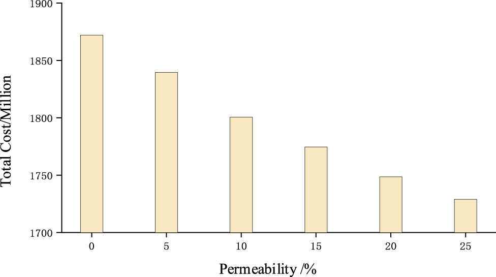
The relationship between distributed power penetration level and total cost.
4 Conclusion
In this paper, the application of distributed power investment decision in multi-stage distribution expansion planning problem is studied, and a multi-stage coordinated planning method for distribution network taking into account distributed power is proposed. Simulation results show that, on the one hand, coordinating the investment decision of distributed power sources with the expansion planning of the distribution network can prevent the problems of isolated and transmission nodes. It also reduces network energy loss, thus improving the reliability of planning results. On the other hand, multi-stage planning can avoid the depreciation cost of equipment generated by overbuilding and equipment redundancy in the early stage of operation. Multi-stage planning is a more rational planning scheme based on the load demand at each planning stage and has good economic benefits.
Statements
Data availability statement
The raw data supporting the conclusions of this article will be made available by the authors, without undue reservation.
Author contributions
QW: conceptualization, methodology, software, resources, formal analysis, investigation, writing—original draft, writing—review and editing. JM: conceptualization, methodology, software, resources, formal analysis, investigation, writing—review and editing.
Conflict of interest
QW is working at State Grid Corporation of China, and at the same time he is a PhD student at NCEPU.
The remaining author declares that the research was conducted in the absence of any commercial or financial relationships that could be construed as a potential conflict of interest.
Publisher’s note
All claims expressed in this article are solely those of the authors and do not necessarily represent those of their affiliated organizations, or those of the publisher, the editors and the reviewers. Any product that may be evaluated in this article, or claim that may be made by its manufacturer, is not guaranteed or endorsed by the publisher.
References
1
Afraz A. Rezaeealam B. Seyedshenava S. Doostizadeh M. (2019). Active Distribution Network Planning Considering Shared Demand Management. Ifs37 (6), 8015–8028. 10.3233/jifs-190420
2
Akbari T. Moghaddam S. Z. (2020). Coordinated Scheme for Expansion Planning of Distribution Networks: A Bilevel Game Approach. IET Generation, Transm. Distribution14 (14), 2839–2846. 10.1049/iet-gtd.2019.1924
3
Alarcon J. A. Santamaria F. Al-Sumaiti A. S. Rivera S. (2020). Low-Capacity Exploitation of Distribution Networks and its Effect on the Planning of Distribution Networks[J]. Energies8 (63), 4562–4573. 10.3390/en13081920
4
Borghei M. Ghassemi M. (2021). Optimal Planning of Microgrids for Resilient Distribution Networks. Int. J. Electr. Power Energ. Syst.128 (52), 106682–106693. 10.1016/j.ijepes.2020.106682
5
Cattani I. B. Chaparro E. Barán B. (2020). Distribution System Operation and Expansion Planning Using Network Reconfiguration[J]. IEEE Latin America Trans.18 (5), 845–852. 10.1109/tla.2020.9082912
6
Delarestaghi J. M. Arefi A. Ledwich G. Borghetti A. (2021). A Distribution Network Planning Model Considering Neighborhood Energy Trading. Electric Power Syst. Res.191 (26), 106894. 10.1016/j.epsr.2020.106894
7
Faria W. R. Martins D. d. B. Nametala C. A. L. Pereira B. R. (2020). Protection System Planning for Distribution Networks: A Probabilistic Approach. Electric Power Syst. Res.189 (15), 106612–106623. 10.1016/j.epsr.2020.106612
8
Franco J. F. (2016). Multistage Long-Term Expansion Planning of Electrical Distribution Systems Considering Multiple Alternatives[J]. IEEE Trans. Power Syst.31 (3), 1900–1914. 10.1109/tpwrs.2015.2443175
9
Hemmati R. Hooshmand R.-A. Taheri N. (2015). Distribution Network Expansion Planning and DG Placement in the Presence of Uncertainties. Int. J. Electr. Power Energ. Syst.73, 665–673. 10.1016/j.ijepes.2015.05.024
10
Jooshaki M. Farzin H. Abbaspour A. Fotuhi-Firuzabad M. Lehtonen M. (2020). A Model for Stochastic Planning of Distribution Network and Autonomous DG Units. IEEE Trans. Ind. Inf.16 (6), 3685–3696. 10.1109/tii.2019.2936280
11
Koutsoukis N. Georgilakis P. (2019). A Chance-Constrained Multistage Planning Method for Active Distribution Networks. Energies12 (21), 4154. 10.3390/en12214154
12
Liu X. Wang L. Wu Y. Wei B. Dongyang Q. (2019). Locating and Sizing Planning of Distributed Generation Power Supply Consid-Ering the Operational Risk Cost of Distribution Network[J]. Trans-actions China Electrotechnical Soc.34 (S1), 264–271. 10.19595/j.cnki.1000-6753.tces.181516
13
Mansor N. N. Levi V. (2018). Operational Planning of Distribution Networks Based on Utility Planning Concepts[J]. IEEE Trans. Power Syst.34 (3), 2114–2127. 10.1109/tpwrs.2018.2885275
14
Masoumi-Amiri S. M. Shahabi M. Barforoushi T. (2021). Interactive Framework Development for Microgrid Expansion Strategy and Distribution Network Expansion Planning. Sustainable Energ. Grids Networks27 (11), 100512–100526. 10.1016/j.segan.2021.100512
15
Mojtahedzadeh S. Ravadanegh S. N. Haghifam M. R. (2021). Microgrid‐based Resilient Distribution Network Planning for a new town. IET Renew. Power Gen15 (15), 3524–3538. 10.1049/rpg2.12241
16
Muoz-Delgado G. Contreras J. Arroyo J. M. (2014). Joint Expansion Planning of Distributed Generation and Distribution Networks[J]. IEEE Trans. Power Syst.30 (5), 2579–2590. 10.1109/TPWRS.2014.2364960
17
Narimani A. Nourbakhsh G. Arefi A. Ledwich G. F. Walker G. R. (2018). SAIDI Constrained Economic Planning and Utilization of Central Storage in Rural Distribution Networks[J]. IEEE Syst. J.13 (1), 842–853. 10.1109/jsyst.2018.2852630
18
National Development and Reform Commission (2015). Several Opin-Ions of the central Committee of the Communist Party of China and the State council on Further Deepening the Reform of the Power System(Zhong Fa[2015]No.9)[EB/OL]. Available at : http://tgs.ndrc.gov.cn/zywj/201601/20160129773852.html.
19
Nikoobakht A. Aghaei J. Massrur H. R. Hemmati R. (2020). Decentralized Hybrid Robust/stochastic Expansion Planning in Coordinated Transmission and Active Distribution Networks for Hosting Large-Scale Wind Energy[J]. IET Generation Transm. Distribution14 (5), 797–807. 10.1049/iet-gtd.2019.0888
20
Saeed H. Mahmud F. F. (2018). Integrated Planning for Distribution Automation and Network Capacity Expansion[J]. IEEE Trans. Smart Grid10 (4), 4279–4288. 10.1109/TSG.2018.2855218
21
Shahbazi A. Aghaei J. Pirouzi S. Niknam T. Shafie-khah M. Catalão J. P. S. (2021). Effects of Resilience-Oriented Design on Distribution Networks Operation Planning. Electric Power Syst. Res.191 (6), 106902–106915. 10.1016/j.epsr.2020.106902
22
Shahbazi A. Aghaei J. Pirouzi S. Niknam T. Vahidinasab V. Shafie-khah M. et al (2021). Holistic Approach to Resilient Electrical Energy Distribution Network Planning. Int. J. Electr. Power Energ. Syst.132 (5), 107212–107226. 10.1016/j.ijepes.2021.107212
23
Tabares A. Franco J. F. Lavorato M. Rider M. J. (2015). Multistage Long-Term Expansion Planning of Electrical Distribution Systems Considering Multiple Alternatives[J]. IEEE Trans. Power Syst.31 (3), 1900–1914. 10.1109/tpwrs.2015.2448942
24
Vahidinasab V. Tabarzadi M. Arasteh H. Alizadeh M. I. Mohammad Beigi M. Sheikhzadeh H. R. et al (2020). Overview of Electric Energy Distribution Networks Expansion Planning. IEEE Access8 (79), 34750–34769. 10.1109/access.2020.2973455
25
Xiao X. Wang F. Shahidehpour M. Li Z. Yan M. (2020). Coordination of Distribution Network Reinforcement and DER Planning in Competitive Market[J]. IEEE Trans. Smart Grid12 (3), 12261–12271. 10.1109/tsg.2020.3026014
26
Xing H. Cheng H. Zhang Y. Zeng P. (2016). Active Distribution Network Expansion Planning Integrating Dispersed Energy Storage Systems. IET Generation, Transm. Distribution10 (3), 638–644. 10.1049/iet-gtd.2015.0411
Summary
Keywords
distributed generation, distribution network planning, multi-stage, planning model, planning scheme
Citation
Wang Q and Jing M (2022) Multi-Stage Expansion Planning of Distribution Network Considering Distributed Power Generation. Front. Energy Res. 10:902891. doi: 10.3389/fenrg.2022.902891
Received
23 March 2022
Accepted
12 April 2022
Published
26 May 2022
Volume
10 - 2022
Edited by
Chaolong Zhang, Anqing Normal University, China
Reviewed by
Yin Yao, Shanghai University of Electric Power, China
Nan Yang, China Three Gorges University, China
Updates
Copyright
© 2022 Wang and Jing.
This is an open-access article distributed under the terms of the Creative Commons Attribution License (CC BY). The use, distribution or reproduction in other forums is permitted, provided the original author(s) and the copyright owner(s) are credited and that the original publication in this journal is cited, in accordance with accepted academic practice. No use, distribution or reproduction is permitted which does not comply with these terms.
*Correspondence: Ma Jing, 3466673668@qq.com
This article was submitted to Smart Grids, a section of the journal Frontiers in Energy Research
Disclaimer
All claims expressed in this article are solely those of the authors and do not necessarily represent those of their affiliated organizations, or those of the publisher, the editors and the reviewers. Any product that may be evaluated in this article or claim that may be made by its manufacturer is not guaranteed or endorsed by the publisher.