 Peidong Chen1
 Yifei Yang
- 1Power Grid Planning Center of Guangdong Power Grid Co., Ltd., Guangzhou, China
- 2School of Electric Power, South China University of Technology, Guangzhou, China
Intelligent distributed control and protection is a promising route towards flexible and safety operation of distribution network with widespread access of distributed energy resources A fundamental premise of the distributed decision-making is that each smart terminal can identify the topological structure of the feeder and track its changes. This paper proposes a distributed topology identification algorithm with high fault tolerance based on peer-to-peer communication. The smart terminal units (STU) installed on the nodes can dynamiclly track and identify the network topology through local measurement and information exchange with neighboring STUs. The proposed algorithm combines local measurement mutual check with contralateral connectivity predictive correction, and significantly improves the tolerance of measurement errors in topology identification. Test examples are presented to verify the effectiveness of the method.
1 Introduction
With the development of distributed generation, power flows in active distribution networks are becoming increasingly complex and unpredictable, and the equipments that need to be automatically monitored and regulated is increasing rapidly. Therefore, distributed control and protection of distribution network are becoming more and more intelligent. State perception and decision making are realized through smart terminal units (STUs) set at key nodes of the network. The adjacent STUs can carry out interactive communication and information exchange, so that the distribution network can operate flexibly under complex conditions without all kinds of disturbances (Zhang et al., 2015).
One of the preconditions for STU to make control decisions such as fault recovery and voltage regulation is to capture the topological structure of the network, identify its location in the distribution network. Taking the reactive power-voltage control in (Šulc et al., 2014; Keqiang et al., 2019; Zhong, 2020) as an example, the control strategy is designed according to the upstream and downstream connection relationship between the nodes. In (Kaijun et al., 2015; Mengyou et al., 2015), the distributed feeder automation algorithms are designed for specific feeder topological structure and the location of tie-switch. The design of protection function of distribution network has similar requirements. For the distribution network with ring structure, operations such as open-loop operation and power supply transfer are frequent, resulting in frequent changes in upstream and downstream relationship. In order to achieve distributed current protection, STUs need to dynamically identify their upstream and downstream connection relationship in two ways: centralized topology identification (Ang et al., 2017) by dispatching master station, and distributed autonomous tracking by peer-to-peer communication and information exchange between distributed control terminals.
The centralized topology identification is carried out according to the switch status and the network operation mode, which require the accurate static structure of distribution network should be stoted in the dispatching master station in advance. The centralized identification algorithms can be divided into two categories: adjacency matrix method and tree search method (Hong, 2008; Guozheng and Bingyin, 2011; Yiming et al., 2012).
Compared with the centralized scheme, the distributed topology identification does not need to perceive the static structure of all the feeders, and has high robustness and anti-disturbance ability. In (Kaijun et al., 2015; Mengyou et al., 2015; Yitong, 2019), each feeder switch is configured with an intelligent terminal (STU), which only needs to pre-store the communication address of its neighbor STU. STU at the source side of the feeder is responsible for sending the switch status and the power supply capacity of the feeder to the adjance STU. The status query is transmitted step by step between STUS until the switch in the off state is found. The upstream and downstream relationship and topological connection information in feeder operation is obtained. STU distributed control is adopted for the cable network in (Guofang et al., 2018), and the control range of each STU covers all switches of each node of cable feeder.
In this paper, a new distributed topology identification algorithm based on peer-to-peer communication is proposed for medium voltage cable distributed network with loop connection and open loop operation. Its characteristics include: 1) Make full use of the current and power measurement information of the network nodes, as well as the switch status, to improve the tolerance of measurement errors. 2) Each STU can predict the switching status of the other side of the line by analysing the analog variables and switch variables, and further check the local topology by exchanging and comparing with the topology identified by the other side. 3) Peer-to-peer communication is used for information exchange. There is no master STU, and each STU only communicates with its neighbor STU. 4) Each STU can track and obtain the complete topology of the feeder. The static topology of feeder groups does not need to be stored in advance. 5) Topology identification and upstream/downstream relationship identification are not affected by distributed generators access and bidirectional power flow.
The process of topology identification, fault tolerance criterion and topology checking scheme are introduced in this paper. The effectiveness of the proposed method is verified by an example of active distribution network with distributed generators.
2 Application scenarios and deployment requirements for distributed topology identification
2.1 Distributed smart terminals
Taking the cable-based distribution network shown in Figure 1 for example. It is a single loop with two 10 kV feeders. The smart terminals are configurated on the loop network nodes. Each terminal is responsible for the monitoring of the bus voltage, branch current and switch status of one loop network node.
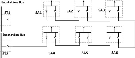
FIGURE 1. STUs in the cable-based distribution network.
In distribution network with open-loop operation, the substation bus can be treated as power supply source of the feeders, which is the basis for judging the upstream and downstream relationship. Therefore, a special label is given for the switch of substation bus. In this paper, ST represents the intelligent terminal corresponding to the substation bus, while other intelligent terminals in the feeders are identified as SA, as shown in Figure 1. They are collectively called STU.
No matter active or passive distribution network, in open-loop operation, there is only one branch of each STU- configured node, connect to the main supply substation. The other side of this branch is called the upstream node. Taking Figure 1 for example, if the open-loop point is on the right switch of SA3, both SA1 and SA2 are upstream nodes of SA3. Obviously, changing the open-loop point will change the upstream and downstream relationship between SAs.
In this paper, the nodes with STU and connecting to the main substation are regarded as upstream nodes, regardless of the power flow direction. If the open-loop point is at the right-side outlet switch of SA3, then SA1 and SA2 are both upstream nodes of SA3. Obviously a different open-loop point will lead to a different upstream/downstream relationship between SAs.
The topology identification method proposed in this paper does not require complete static topology information that is preset and stored in the ST or SA. Each ST or SA only needs the identification information of its neighboring terminals. Here, SAj is the “neighboring terminal” of SAi, the distribution branch connecting SAi and SAj does not need to pass through the supervisory bus of any other smart terminal. Table 1 summarizes the basic topology and communication information that needs to be stored in the SA.
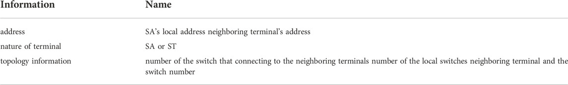
TABLE 1. Basic topology information stored in STU.
Preset topology information connection can greatly reduce the maintenance workload in operation and management. When the topological structure changes, for example, a new loop network node is inserted between SA1 and SA2 in Figure 1, only information of adjacent terminals of SA1 and SA2 needs to be changed, without any modification of other terminals.
2.2 Real-time measurements of smart terminal unit
STUs are responsible for monitoring and protecting the operation of the distribution network. Therefore, one of their basic tasks is to collect real-time data on the electric parameters of the loop network node and the switch status. The topology identification algorithm proposed in this paper functions during the steady-state operation, and the required real-time monitoring data are shown in Table 2.
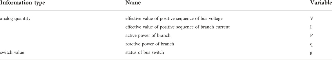
TABLE 2. Monitoring data required in topology identification.
The operating information mentioned above can be obtained by calculating the bus voltage and branch current data are collected regularly by STU.
It is worth noting that the method proposed in this paper is designed for active distribution networks. The STU power supply branches may contain power load, distributed power source and energy storage devices, and the power flows can be bi-directional.
3 Distributed topology identification
3.1 Flow of the algorithm
In this paper, STU and its neighbors regularly communicate peer-to-peer and exchange information. The identification period is equal to the sampling period. In one cycle, each STU completes one local measurement, one information exchange with neighbor, multiple information analysis and topology identification logic. Each STU independently makes the judgment of the topological relationship of the distribution network. The topology identification process for each cycle is shown in Figure 2.
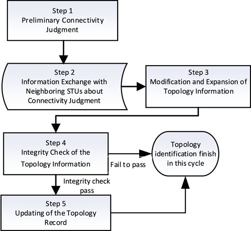
FIGURE 2. Flow chart of topology identification algorithm.
The technical solutions of each link of topology identification are described below.
3.2 Connectivity judgment
According to the updated real-time information, STU performs the first prediction based on the switching state of the branches. Moreover, STU can make a preliminary judgment about the branch connectivity between itself and neighboring STUs, as well as the switch state of the opposite side of the branch. The two STUs can exchange their information, and each STU can use the information from the STU on the opposite side to correct judgments about the status of the switch, thus improving the accuracy of topology identification and fault-tolerant of measurement faults.
Note that the STU in the loop network node is x, the branch that requires connectivity judgment is k, the switch number on the local side is (x, k), the neighbor STU on the opposite side of the branch is y, and the switch number on the y side of the branch is (y, k). The preliminary judgment of connectivity include {S’x,k, cx,k} and {S’y,k, cy,k}. Table 3 shows the meanings and value ranges of variables S’ and c. In the table, confidence c represents the credibility of the judgment. The confidence degree is divided into three grades, which are: 1 - confident; 0 - Untrusted; 0.5 - guess. There are also three feasible values for the judgment of switch on/off state S’: 0/1/Null corresponding to switch off, closed and unknown state respectively. ε is a small positive integer slightly larger than the normal measurement error.

TABLE 3. Connectivity status of STU.
Figure 3 shows the rules for initial connectivity judgment based on local measurements, and the measurement symbols are shown in Table 2.
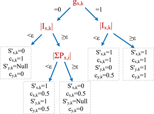
FIGURE 3. Decision tree for connectivity judgment.
It can be seen that the absolute value of current and active power is used to construct the rule tree, which is not affected by current direction and power supply direction. Therefore, it is suitable for both the active distribution network with distributed generators and the passive distribution network with unidirectional power flow.
Check the switch status by measuring switch status g, which is the root node in Figure 3. Considering the measurement errors, the mutual checking logic of analog quantity is designed to increase the fault tolerance, as follows:
1) If the branch current measurement is consistent with the switch state measurement logic, the local connectivity is judged as confidence value 1, i.e., the leftmost and rightmost branches in Figure 3. At the same time, if the switch is on and current is detected in the branch, it can predict that the opposite switch is on. On the contrary, when the switch is off and there is no current in the branch, the opposite switch state cannot be predicted.
2) If the switch state is off but the branch detectes current, calculate whether the sum of the active power flowing into the bus through all branches is zero (power balance) to assist judging whether the measurement has an error. If the power and current criteria are logically consistent, change the judgment to connect and express the confidence as 0.5. Otherwise, the disconnection is judged as confidence value 0.5. See the second and third left leaf nodes in Figure 3.
3) If the switch status is closed but the branch current is zero, it may be because the switch on the opposite side of the branch is off, there is no logical conflict. Therefore, the confidence degree 1 represents that the switch of the local side is on, while the confidence value 0.5 represents that the switch of the opposite side is off.
3.3 Information exchange with neighboring smart terminal units about connectivity judgment
Based on preliminary judgment on switch status of branch, each STU forms an overall judgment on the connectivity between itself and its neighboring STUs according to the following rules:
Rule 1: If the value of switch status on either side is 1, then the value of branch status is 1 (connected), and the confidence takes the smaller value c of the two switches.
Rule 2: If the value of switch status on the two sides is 1 and 0 respectively, then the value of branch status is 0 (disconnected) and the confidence of the branch status takes the value corresponding to the switch status value of 0.
Rule 3: If the switch status on the opposite side is unknown (Null), then the branch status and the confidence are determined by the local switch status, i.e., the connectivity status and confidence level of the branch are consistent with the closed/open state and the confidence of the local switch.
Topological relationship between the STU and the feeder is described as shown in Table 4, one row for one branch.
1) The branch name represents the name of the branch between two adjancent STUs, and the name of the switch is represented by the SA number and the switch number.
2) The branch status records the judgment of the branch’s connectivity status (0/1) and the confidence level.
3) The switch status records the switch status (0/1) on each side of the branch and the confidence level.
4) The label gives the source of information, i.e., offering the SA number that provides the information.

TABLE 4. The topology information table in STU.
After finishing the information record in Table 4, the STU sends the record to all neighboring STUs. At the same time, it waits to receive exchange information from its neighboring STUs.
3.4 Modification and expansion of topology
After the STU receives topology information from its neighbors, it modifies and expands its own topology information record table according to the following rules.
Rule 1: If the STU’s table does not include information of a certain branch that is recorded by a neighboring STU, it expands the table by copying the information of that branch. Otherwise, it updates the record according to rules 2-4.
Rule 2: If the STU’s judgment confidence value of the local switch status is 1, it continues to use its own judgment on the local switch status and the confidence.
Rule 3: If a neighboring STU’s confidence value of its judgment on the switch status on the opposite side of the branch is 1, the STU updates its own record of the opposite side switch by adopting the neighboring STU’s judgment on the switch status and the confidence.
Rule 4: If a neighboring STU’s judgment on the local switch’s status is different from that of this STU and its confidence value is also higher than that of this STU, then the STU uses its own judgment on the switch status and takes the smaller one of the two confidence values as the final judgment confidence.
Rule 5: If the STU’s judgment on the opposite switch status is different from that of the opposite STU and its confidence value is higher, it uses its own judgment on the opposite switch status and takes the smaller one of the two confidence values as the final judgment confidence.
After updating the information about the switch status according to the above rules, the STU starts to update the information about the branch status according to the same rules in Section 3.3. It can be seen that the topology information sent by the neighboring STUs can expand this STU’s topological horizon until the topology identification covering the whole feeder group is completed.
3.5 Integrity check of the topology information and updating of the topology record
The STU performs an integrity check of the topological information recorded in the previous step. First, a breadth-first search is carried out starting with the record of this labeled STU itself. If the branch that connects the nodes is shown to be connected, the STU on the opposite side of the branch is added to the labeled nodes to be searched next, until the search of an undirected topology tree is completed. Then, another record not included in the topology tree will be randomly selected, whose labeled STU will be taken as the starting point of a new topology tree search until all topology trees are searched.
If a topology tree has one and only one ST-typed node, then the topology tree passes the integrity check. Otherwise, it fails to pass the integrity check.
If the topology tree containing the STU node passes the integrity check, the topology identification module will output all the topology records that have passed the integrity check to the shared data area of STUs for other control and protection function modules to use the topology information as required.
When the “ST” node in the undirected topology tree is taken as the root node, a directed topology tree will be conveniently generated with upstream and downstream relationships. The upper node becomes the upstream node of the lower node.
If the topology tree containing the STU node fails to pass the integrity check because there is no “ST” node in it, then topology identification will be considered unfinished, and the recorded information will be kept for the next cycle and then expanded.
If the topology tree containing the STU node fails to pass the integrity check because there are several ST nodes in it, topology identification will be considered erroneous. The information of all other labeled STUs in the topology tree will be deleted and topology identification will restart.
4 Algorithm test and result analysis
As is shown in Figure 4, the effectiveness of the proposed topology identification algorithm is tested in a distribution network with eight nodes. The simulation model of the system is created. In the initial state, all branch switches in the network are on. It is assumed that at 0.4s, the switch K3-2 changes from on to on. Line parameters, node load, and characteristic quantities such as switch status, branch current and the sum of branch active power collected by each SA under this operation mode are shown in Supplementary Appendix S1. Then, one scenario is designed to verify the topology tracking capability and fault tolerance of the method.
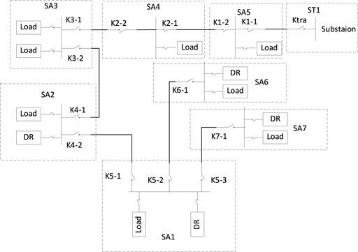
FIGURE 4. Schematic diagram of 8-node distribution network and its STU deployment.
4.1 Topology identification process
Taking SA1 as an example to illustrate the topology identification process. Preliminary judgment of SA1 in Round 1 on its connectivity with neighboring branches based on information from its neighbors are shown in Table 5.
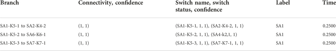
TABLE 5. Preliminary judgement of SA1 in Round 1.
Next, SA1 exchanges judgment information with the neighboring terminals SA2, SA4, and SA6. The topology information SA1 receives from SA2 is respectively expressed in Table 6.
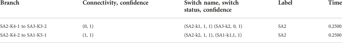
TABLE 6. Exchange information from SA2 in Round 1.
Based on the exchange information, SA1 expands its topological record as is shown in Table 7.
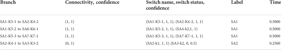
TABLE 7. Topology table of SA1 in Round 2.
SA1 then performs a topology tree search and an integrity check according to this table and concludes that there is no ST node in the topology tree so it fails to pass the integrity check and topology identification is not yet finished. It keeps the record till the next cycle of topology identification. After 3 cycles, SA1 obtains complete topology information and outputs the current topology information that has passed the integrity check. The topology information stored in SA1 at this point is shown in Table 8.
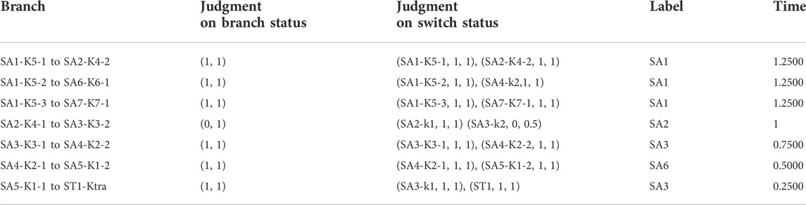
TABLE 8. Topology table of SA1 in Round 5.
Based on Table 8, a directed topology tree is generated as shown in Figure 5.
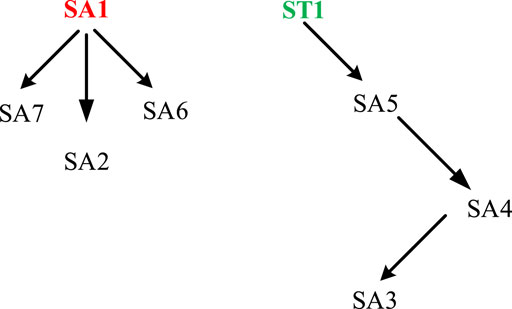
FIGURE 5. The directed topology obtained by SA1.
As the test example shows, all STUs in this scheme can obtain the complete topology of the whole feeder group, not only limited to the topology tree of their feeder in the current open-loop operation mode. The scheme can provide technical support for distributed control, such as distributed self-healing in distribution network.
4.2 Topology identification in the case of measurement error
The confidence and interactive verification rules in this paper improve the STU’s fault tolerance for measurement errors. In the initial state, switches Ktra, K1-1,K1-2,K2-1,K2-2,K3-1,K3-2,K4-1,K4-2,K5-1,K5-2,K5-3, K6-1, K6-2 are closed. Switch K3-2 disconnects at 0.4s, and a measurement error of current data occurs, which exceeds the measurement error value and makes the sum of absolute values of active power of each switch on node 3 exceed the error value. In this case, the topology information stored in SA1 in Round 2 is shown in Table 9.
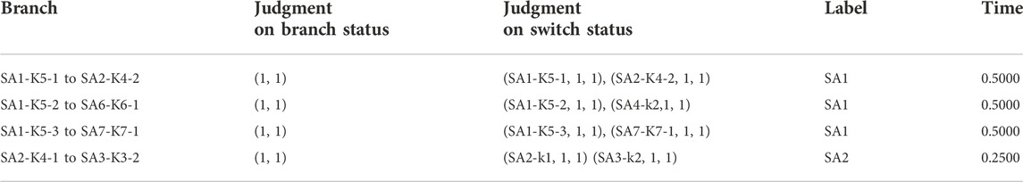
TABLE 9. Topology table of SA1 in Round 2 with measurement error.
Correspondingly, errors also occur in SA1’s judgment on the local switch status and the branch status. However, after exchanging information with SA2, SA1 implements correct topology identification by replacing its lower-confidence judgment information with SA2’s higher-confidence judgment. The topology information stored in SA1 in Round 5 is shown in Table 10.

TABLE 10. Topology table of SA1 in Round 5 with measurement error.
If a communication failure occurs among some STUs, the affected STUs will lose the neighbor’s information check and lose confidence in the connectivity judgment. Meanwhile, it is hard to update the upstream or downstream topology status of the corresponding communication failure area. As analyzed in Section 3.5, short-term communication interruption only affects topology update, does not affect the topology records exchange and STU control functions. However, if the communication interruption lasts for a long time, it is recommended to lock the distributed protection logic which requires accurate upstream and downstream relation criterion.
In addition, each STU gradually expands the sensing domain through the information exchange between its neighbors, so STU at different locations in the power grid would obtain the complete topology of its feeder and other feeder groups at different times. For any STUx, the time it takes to implement a complete topology update is the product of two parameters. One is the identification period Ts, and the other is the maximum number of STU through different ST to STUx paths in the feeder group, nmax. As the identification process in Section 2 is mainly based on logical judgment, less computing resources are occupied. Information exchange is state exchange, less communication resource consumption, so identification cycle mainly depends on sampling rate and communication mode. Considering that the purpose of this paper is to track changes in power grid topology and normal operation mode, the refresh cycle should not be too small, so Ts = 100 ms is recommended. In general, the typical number of trunk ring nodes of a single feeder in the cable network is 6, and the total number of STUs on the main channel connected by two feeders is 12. If nmax = 12, the refresh period for different STUs in feeder groups to obtain a complete topology is 0.6–1.2 s. It can meet the topology refresh requirement of distributed control including self-healing control.
5 Conclusion
In this paper, a highly fault-tolerant topology identification algorithm based on distributed control is proposed. The proposed algorithm gives full play to the STU’s ability to make flexible rule-based judgment, expand its scope of observation, and adjust its judgment through information exchange with the neighboring STUs. The proposed algorithm does not require pre-set static topology information of the distribution network and can implement fast operational topology identification and updating. The design takes into account adaptability to bi-directional currents of the active distribution network and fault tolerance to measurement errors. Different terminals can implement distributed updating of topology information about the entire network without relying on the master station. The proposed algorithm provides topology information support for the implementation of application functions such as distributed operation control and protection of the distribution network
Data availability statement
The original contributions presented in the study are included in the article/Supplementary Material, further inquiries can be directed to the corresponding author.
Author contributions
PC, conceived and designed the algorithm, wrote the paper. HC, contributed data and analysis tools. XH, collected and analyzed the data. YY, performed the analysis. LL, designed the algorithm, wrote the paper.
Funding
This work was supported by The Science and Technology Project of China Southern Power Grid [037700KK52200001(GDKJXM20200463)]. The funder was not involved in the study design, collection, analysis, interpretation of data, the writing of this article, or the decision to submit it for publication.
Conflict of interest
PC, HC and XH were Power Grid Planning Center of Guangdong Power Grid Co., Ltd.
The remaining authors declare that the research was conducted in the absence of any commercial or financial relationships that could be construed as a potential conflict of interest.
Publisher’s note
All claims expressed in this article are solely those of the authors and do not necessarily represent those of their affiliated organizations, or those of the publisher, the editors and the reviewers. Any product that may be evaluated in this article, or claim that may be made by its manufacturer, is not guaranteed or endorsed by the publisher.
Supplementary material
The Supplementary Material for this article can be found online at: https://www.frontiersin.org/articles/10.3389/fenrg.2022.910518/full#supplementary-material
References
Ang, L., Yadong, L., Peng, S., Lingen, L., and XIuchen, J. (2017). Distribution network topology identification method based on phase data by µPMU. Smart Grid 45 (11), 31–36. doi:10.3969/j.issn.1673-7598.2017.11.006
Guofang, Z., Peifeng, S., Yong, W., and Haitai, Z. (2018). Dynamic identification method of feeder topology for distributed feeder automation based on topological slices. Power Syst. Prot. Control 46 (14), 152–157. doi:10.7667/PSPC171001
Guozheng, H., and Bingyin, X. (2011). Circuit oriented topology analysis of medium-voltage distribution network. South. Power Syst. Technol. 5 (01), 61–64. doi:10.13648/j.cnki.issn1674-0629.2011.01.016
Hong, L. (2008). Research on topology analysis method of distribution network. Chengdu: University of Electronic Science and Technology of China. [master’s thesis]. [Chengdu].
Kaijun, F., Bingyin, X., Zhengyi, X., Jinghua, W., Jun, D., and Hongchun, S. (2015). Identification method for feeder topology based on successive polling of smart terminal unit. Automation Electr. Power Syst. 39 (11), 180–186. doi:10.7500/AEPS20150106010
Keqiang, L., Xueshan, H., Huadong, L., and Wenbo, L. (2019). Distributed algorithm for optimal power flow pursuit by photovoltaic inverters in distribution systems. Proc. CSEE 39 (03), 711–720+950. doi:10.1109/CDC.2015.7403309
Mengyou, G., Bingyin, X., Kaijun, F., and Xinhui, Z. (2015). Distributed feeder automation based on automatic recognition of real-time feeder topology. Automation Electr. Power Syst. 39 (9), 127–131. doi:10.7500/AEPS20140604003
Šulc, P., Backhaus, S., and Chertkov, M. (2014). Optimal distributed control of reactive power via the alternating direction method of multipliers. IEEE Trans. Energy Convers. 29 (4), 968–977. doi:10.1109/tec.2014.2363196
Yiming, L., Dong, L., Yuhui, H., Wenpeng, Y., and Jianwei, G. (2012). Feeder modeling and application based on CIM. Proc. CSEE. 32(28): 157–163. doi:10.13334/j.0258-8013.pcsee.2012.28.021
Yitong, W. (2019). Distributed topology identification and application method of smart distribution network. Power Syst. Prot. Control 47 (16), 136–142. doi:10.7500/AEPS20161228008
Zhang, B., Lam, A. Y. S., Domínguez-garcía, A. D., and Tse, D. (2015). An optimal and distributed method for voltage regulation in power distribution systems. IEEE Trans. Power Syst. 30 (4), 1714–1726. doi:10.1109/tpwrs.2014.2347281
Zheng, W., Wu, W., Zhang, B., Sun, H, Yibing, L, et al. (2016). A fully distributed reactive power optimization and control method for active distribution networks. IEEE Trans. Smart Grid 7 (2), 1021–1033. doi:10.1109/tsg.2015.2396493
Keywords: the distribution network, smart terminal unit (STU), topology identification, distributed control, neighboring interaction
Citation: Chen P, Cao H, He X, Yang Y and Lin L (2023) Distributed topology identification algorithm of distribution network based on neighboring interaction. Front. Energy Res. 10:910518. doi: 10.3389/fenrg.2022.910518
Received: 01 April 2022; Accepted: 08 July 2022;
Published: 23 January 2023.
Edited by:
Zhiyi Li, Zhejiang University, ChinaReviewed by:
Zhi-Wei Liu, Huazhong University of Science and Technology, ChinaDazhong Ma, Northeastern University, China
Copyright © 2023 Chen, Cao, He, Yang and Lin. This is an open-access article distributed under the terms of the Creative Commons Attribution License (CC BY). The use, distribution or reproduction in other forums is permitted, provided the original author(s) and the copyright owner(s) are credited and that the original publication in this journal is cited, in accordance with accepted academic practice. No use, distribution or reproduction is permitted which does not comply with these terms.
*Correspondence: Lingxue Lin, bGlubHhAc2N1dC5lZHUuY24=