 Zhenggui Li1*
 Kun Wang
 Shengnan Yan
 Fang Chen
 Shengyang Peng
- 1Key Laboratory of Fluid and Power Machinery, Ministry of Education, Xihua University, Chengdu, China
- 2Huaneng Mingtai Electric Power Co. Ltd., Mianyang, China
In order to discuss the surface pressure pulsation characteristics of the magnetic-fluid sealing membrane of centrifugal pump, this paper studies the surface pressure pulsation characteristics of the shaft end sealing membrane under different flow operating conditions of centrifugal pump based on the combination of numerical calculation and experimental verification. The results show that the pressure value on the surface of the magnetic-fluid sealing film decreases with the increase of the flow rate of the centrifugal pump, and the pressure on the surface of the magnetic-fluid sealing film has periodic pulsation, and the period is the time required for a single blade to sweep the volute separating tongue. In one rotation cycle of the runner, the number of reciprocating movements of the magnetic-hydraulic sealing film is the same as the number of blades of the runner. The main reason for the pressure pulsation is that the impeller periodically sweeps the fixed surface of the centrifugal pump.
Introduction
As an important strategic machine for the national economy, people’s livelihood and national security, the development of industry and science and technology, the demand for energy and the environment, and the construction of the national economy all promote the development of pumps in the direction of high speed, high efficiency and high stability Lu (2017). However, the high-speed operation of the centrifugal pump also causes the unreliability of the shaft end seal of the centrifugal pump. In order to prevent seal failure, leakage of liquid in the pump or impurities outside the pump from entering the pump cavity, the shaft seal must be considered when designing and applying centrifugal pumps Peng (2021); Xu (2004); Zhao et al. (2001). Magnetic liquid seal is a new type of non-contact seal, which shows good advantages in dynamic sealing Li W. et al. (2021); Li et al. (2022). It has been widely used in dry Roots vacuum pump Li et al. (2002), reactor Xu. (2013) and other equipment. However, there has not been a major breakthrough in the magnetic liquid sealing technology of the centrifugal pump shaft end using liquid as the transport medium. The fundamental reason is that the surface of the magnetic liquid sealing film is unstable. Therefore, scholars at home and abroad have explored the principle of magnetic liquid sealing.
Jianfeng Zhou and Haoliang Fan (Zhou et al., 2016) studied the influence of magnetic field strength and rotational speed on film thickness, friction torque, characteristic temperature and magnetohydrodynamic loss, revealing the influence of magnetic field on magnetohydrodynamic effect; Zhang Haina (Zhang et al., 2013) studied the influence of sealing progression, magnetic liquid injection amount and standing time at room temperature on the tripping torque, and at the same time, based on the magnetic liquid rotary sealing model, the torque formula of magnetic liquid rotary sealing at low temperature was derived from the Navier-Stokes equation; Jibin Zou (Zou et al., 2003) discovered that multi-pole multi-stage magnetic fluid sealing is an effective way to obtain higher sealing capacity, and studied the method of magnetic fluid filling and differential pressure application; Yibiao Chen (Chen et al., 2020) et al. studied the variation of magnetic fluid temperature and its influence on sealing performance; In order to establish a stable interface in the sealing process, Tonggang Liu (Liu et al., 2005) optimized the structural parameters by using the simulation device, and developed a new type of magnetic fluid seal, which has good sealing performance and long service life according to the optimization parameters; Marcin, Szczech (Szczech M. 2020) introduced the leakage mechanism between multi-stage magnetic fluid seals when magnetic fluids were applied to magnetic fluid seals in rotational motion, and Marcin, Szczech (Szczech M. 2018) proposed a critical pressure calculation method for magnetic fluid seals based on numerical simulation of magnetic fields, which had better calculation effect than previous methods; Qian Jiguo et al. (Qian and Yang, 2008) elaborated on the interfacial stability analysis method of the magnetic liquid sealed liquid, and obtained the stability criterion and the critical value of the parameters of the interface between the magnetic liquid and the sealed liquid according to the Kelvin-Helmholtz interface stability analysis model of the moving fluid, and discussed the main factors affecting the stability of the liquid-liquid interface of the magnetic liquid dynamic seal. The above scholars analyzed the influence of magnetic fluid temperature and sealing series on sealing performance, and optimized the magnetic liquid sealing performance in combination with numerical calculations, and studied the stability of the magnetic liquid sealing interface and improved its related theory, but at present, there is a lack of research on the stability of the surface of the magnetic liquid sealing film at the shaft end when the centrifugal pump operates at high speed under different flow conditions.
However, the surface pressure ripple of the magnetic seal film is an important cause of the emulsification, dilution, dissolution and sealing failure of the magnetic liquid (He et al., 2014). In rotating machinery with impeller, due to its special structure, the periodic sweeping of the fixed surface of the impeller, the reflection of the pressure fluctuations on the wall surface of the volute, the complex three-dimensional transient flow during the normal operation of the centrifugal pump, the extrusion of the high-pressure fluid in the sealing channel to the surrounding low-pressure fluid, the fluid return flow, and the fluid vortex movement will all produce pressure pulsations on the surface of the magnetic liquid sealing film (Li Z. et al., 2021). Magnetic liquid seal is the use of magnetic liquid where the magnetic pressure difference (Xu et al., 2010) to achieve the sealing effect, so the position of the magnetic liquid at the bottom of the polar tooth corresponds to the pressure bearing capacity: when the pressure of the sealing interface changes, the axial position of the magnetic liquid will change accordingly, when the pressure is pulsating, the surface state of the magnetic liquid sealing film is unstable, if the maximum pulsation amplitude is higher than the maximum pressure of the seal, the sealing film will rupture, as shown in Figure 1.
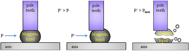
FIGURE 1. The sealing film fluctuates and breaks.
Therefore, it has certain research significance to study the pressure pulsation law on the surface of the magnetic fluid sealing membrane at the shaft end and its causes under various flow conditions of the centrifugal pump.
Numerical Model and Calculation Setup
Division of 3D Model and Mesh Model
The centrifugal pump selected in this article is a single-stage single-suction model pump, and its overcurrent components are composed of inlet runner, connecting runner, mouth ring, volute, impeller, pump chamber, and outlet runner, and the pump chamber contains a leaking runner and a sealed runner inside the pump chamber. Figure 2 shows a model of the pump and a partial mesh of the pump, and Figure 3 is a Schematic diagram of the interior of the pump chamber, with a full-flow channel model of the pump plotted with NX.10. The computational stability, calculation accuracy and calculation speed reflected in the structural grid are better than those of non-structural grids, so the structural grid drawn by ICEM CFD is used for numerical calculation. Winslow P. et al. (2010); Guo et al. (2019); Cheng et al. (2021); Zeng, (2022); Cheng et al. (2022).
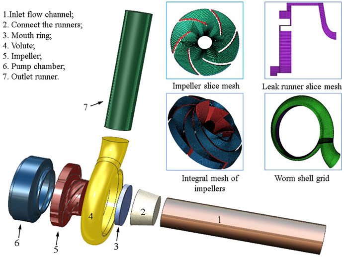
FIGURE 2. Centrifugal pump model and partial grid diagram.
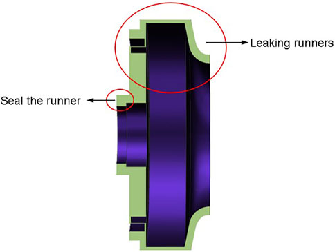
FIGURE 3. Schematic diagram of the interior of the pump chamber.
The main parameters of the model pump are shown in Table 1. In order to eliminate the influence of the number of grids on the calculation results, before the analysis of the results, the external characteristics of the centrifugal pump’s rated operating conditions—the head are taken as the criterion, and the grid independence is verified, as shown in Table 2, when the overall number of grids is greater than 2317541, the head change of the centrifugal pump is less than 0.3%, so it can be considered that the number of grids is greater than this value to meet the calculation requirements.
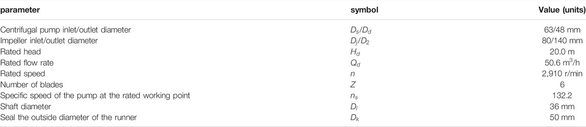
TABLE 1. Main parameters of centrifugal pump.

TABLE 2. Grid model parameters of centrifugal pump.
Boundary Condition Settings
The centrifugal pump test bench used in the experiment is equipped with a pressure sensor at the pump inlet to collect the pressure value of the centrifugal pump inlet; at the same time, a turbine flowmeter is set at the outlet of the pump, so the mass flow of the pump outlet is known, so the pressure inlet is used as the inlet boundary condition, and the flow outlet is used as the outlet boundary condition.
Because the internal structure of the centrifugal pump is known, and the rotor area is different from other overcurrent components, which carries out independent rotational motion, the single reference frame (SRF) model is selected for the steady-state calculation of the flow field in the centrifugal pump, the sliding mesh model is selected for transient calculation, and the impeller surface is set to relatively static to the rotation domain, and the rest of the wall surface is set to absolute stationary.
For the flow state of the flow field in the centrifugal pump, due to the boundary conditions and the complexity of the structure in the pump, the internal rotation area and strong swirl, the RNG k-ε model has corrected the turbulence viscosity, which is suitable for the numerical calculation of strong flow line bending and vortex, so the turbulence model selected in this paper is the RNG k-ε model. Zhou et al. (2007); Ren et al. (2009).
Transient Calculation Parameter Setting
Taking the calculation result of the stable flow field as the initial value of the transient calculation can accelerate convergence and ensure the stability of the calculation, therefore, the constant result of each flow condition is used as the initial condition for the transient calculation of each flow condition of the centrifugal pump. At the same time, in order to better capture the pressure pulsation signal, the transient time step is set to 0.00017182 s, that is, the pressure value is recorded every 3° rotation of the rotor.
In the initial process of transient calculations, the results are often unstable, deviating from the exact solution (Cao et al., 2019). In order to avoid the difference in results caused by these problems, the centrifugal pump wheel is set to rotate a total of 12 turns, the calculation time is 3.77 s, and the results of the last four turns are taken for analysis.
Pressure pulsation monitoring point is set on the surface of the magnetic liquid sealing film, starting from the shaft surface, every 0.1 mm to take a monitoring point, because the sealing gap is 0.3 mm, so the monitoring point is a total of 4, Figure 4 is the monitoring point setting diagram.
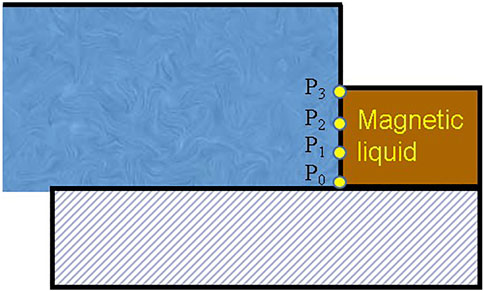
FIGURE 4. Position of monitoring point.
Experimental Verification of Numerical Calculation of Flow Field in Centrifugal Pump
In order to verify the accuracy of turbulence model selection, boundary condition setting and calculation results, the external characteristics of the model pump were tested in the Key Laboratory of Fluid and Power Machinery of the Ministry of Education of Xihua University, and the experimental apparatus is shown in Figure 5:
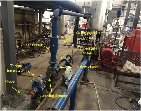
FIGURE 5. Field experimentation.
The experimental bench is an open experimental bench, centrifugal pump inlet and outlet with pressure sensor, and turbine flowmeter, prime mover for the motor, through the torque sensor to drive the centrifugal pump rotation, under the deck of the experimental device, with a water tank, to give the pump body water source, and accept the liquid flowing out of the pump, forming a closed loop.
During the experiment, the centrifugal pump 0.4–1.3Qd working conditions, when the working conditions are adjusted, the data is temporarily not recorded, and the data is collected after the flow is stable. Figure 6 shows the external characteristic data (head, efficiency) collected by the experiment compared with the numerically calculated data.
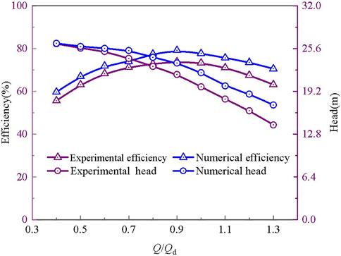
FIGURE 6. Comparison of simulation results with experiments.
The head H of the pump is the energy appreciation of the liquid pumped by the pump per unit weight from the inlet of the pump to the outlet of the pump, and its calculation formula is:
Wherein, the
The efficiency
wherein, the
where T is the torque and
It can also be concluded from Figure 6 that the head and efficiency of the numerical calculation are higher than the experimental values, and the main reason for this phenomenon is that the obstruction and wear effect of the solid surface on the liquid is not considered in the numerical calculation process (Hu 2004). However, the numerically calculated head and centrifugal pump efficiency values are the same as the experimental values, and the maximum deviation value of the head is less than 3 m, so it can be considered that the results of the numerical calculation have a certain degree of credibility.
Pressure Pulsation Analysis of Sealing Film at the Shaft End of Centrifugal Pump
Time Domain Characteristics of Surface Pressure Pulsation of Magnetic Liquid Sealing Film Under Rated Working Conditions
Figure 7 is a time domain diagram of the surface pressure ripple of the magnetic liquid sealing film under rated operating conditions. It can be seen from the figure that the time difference between the adjacent two positive peaks is about 0.0034 s, that is, 20 time steps, and in each time step, the wheel can be rotated by 3°, and the number of blades of the centrifugal pump applied herein is 6, therefore, the time difference between the adjacent two positive peaks is similar to the time required for the wheel to rotate 60°, so the time difference between the adjacent two positive peaks is equal to the time required for one blade to sweep through the septum of the centrifugal pump. Therefore, the pressure pulsation cycle on the surface of the magnetic-liquid seal film is equal to the time required for a single leaf to sweep through the septum.
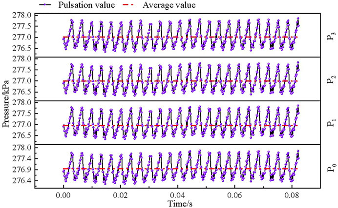
FIGURE 7. Time domain diagram of pressure pulsation under rated operating conditions.
Table 3 shows the negative peak, average and positive peak data of pressure pulsation at each monitoring point on the surface of the magnetic liquid sealing film. From Table 3, it can be seen that under the rated working conditions, the difference between the negative peaks, average values and positive peaks between the monitoring points at the same time point is less than 100 Pa, and the pressure pulsation law of the monitoring points on the surface of the magnetic liquid sealing film can be considered to be consistent under the rated working conditions. And under the rated working conditions, the peak-to-peak difference between the surface of the magnetic liquid sealing film is about 1,500 Pa.
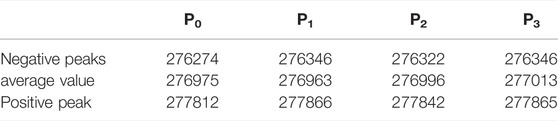
TABLE 3. Pressure pulsation at each monitoring point.
From the above analysis, it can be seen that the time interval and pressure pulsation cycle between the adjacent two pressure peaks are the time required for a single blade to sweep through the septum, and during the magnetic liquid sealing process, the position of the sealing film corresponds to the external pressure one-to-one, so the pressure pulsation cycle on the surface of the sealing film is the displacement movement cycle of the sealing film. Therefore, in a rotary rotation cycle, the magnetic liquid sealing film reciprocates 6 times, and the number of reciprocating movements is the same as the number of blades. At the same time, the pressure amplitude change on the surface of the magnetic liquid sealing film is about 1,500 Pa, while the single-stage sealing capacity of the magnetic liquid is about 120 kPa (Wang, 2004), so the pressure fluctuation on the surface of the magnetic liquid sealing film in the centrifugal pump is less likely to cause a breakdown pressure, and the available pressure average is used as the benchmark when the magnetic liquid sealing device is designed. However, when the centrifugal pump speed is high, the frequency of pressure pulsation fluctuations on the surface of the sealing film is accelerated, which will promote the emulsification, dilution and dissolution of the magnetic liquid.
Time Domain Characteristics of Surface Pressure Pulsation of Magnetic Liquid Sealing Film Under Partial Working Conditions
Figure 8 is a time domain diagram of the surface pressure ripple of the magnetic liquid sealing film of the centrifugal pump under partial working conditions. It can be seen from the figure that under various working conditions, due to the narrow sealing gap, the pressure pulsation time domain curves of each monitoring point on the surface of the magnetic liquid sealing film overlap together. That is, when the centrifugal pump is running under the working conditions of 0.4–1.3Qd flow, the pressure fluctuation law of each monitoring point is consistent. In the subsequent analysis, the pressure value of any point in P0, P1, P2, P3 can be applied instead of the surface pressure value of the magnetic liquid sealing film, and the P2 point is used as the representative point.
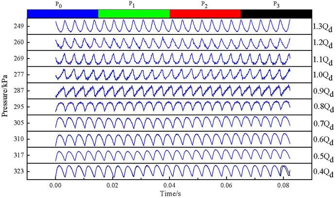
FIGURE 8. Time domain diagram of pressure pulsation under partial conditions.
And from Figure 8, it can also be learned that when the centrifugal pump is running under the working conditions of 0.4–1.3 Qd flow, the fluctuation cycle of the pressure pulsation on the surface of the magnetic liquid sealing film is consistent, which is the length of time required for a single blade to sweep the septum, which shows that when the centrifugal pump is running under different flow conditions, the impact on the periodicity of the pressure pulsation of the magnetic liquid sealing film surface is weak, and it can be inferred from this result that the pressure pulsation on the surface of the magnetic liquid sealing film is mainly generated by the periodic sweeping fixed surface of the blade. Although the periodic sweeping of the fixed surface of the blade dominates the pressure ripple of the magnetic liquid sealing film, the reflection of the pressure fluctuation of the volute wall surface, the complex three-dimensional transient flow during the normal operation of the centrifugal pump, the extrusion of the high-pressure fluid in the sealing channel on the surrounding low-pressure fluid, the fluid return flow, and the fluid vortex movement will have a certain impact on the pressure ripple on the surface of the magnetic-liquid sealing film, so there are differences in the waveform of the pressure ripple under each flow condition.
In order to better compare the law of the surface pressure pulsation characteristics of the magnetic liquid sealing film under various flow conditions, the pressure pulsation value is dimensionlessly treated, and the pressure pulsation coefficient is used as the standard for measuring the size of the pressure fluctuation, and its definition is as follows (Jin, 2020):
where
Figure 9 is a pressure ripple pattern of each flow condition after the dimensionless treatment of the pressure amplitude, it can be seen from the figure that there is a phase difference in the pressure fluctuation law under each flow condition, but its pulsation period is similar. And it can be seen that under the condition of 1.3Qd, the positive peak of the surface pressure pulsation of the magnetic liquid sealing film is the largest, and the negative peak of the pressure pulsation under the condition of 0.4Qd is the largest, but only from the positive peak or negative peak size can not judge the stability of the magnetic seal film under each working condition, because in the process of magnetic sealing, in a pulsation cycle, the magnetic liquid displacement distance is determined by the difference between the positive peak and the negative peak. Therefore, the fluctuation of the magnetic liquid sealing film must be judged by the difference between peak and peak.
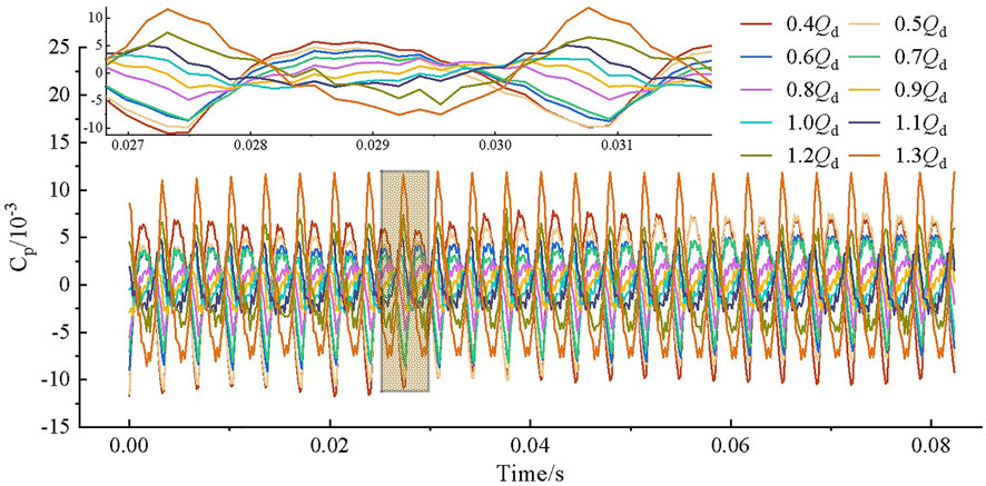
FIGURE 9. Time domain diagram of pressure pulsation under dimensionless partial conditions.
Figure 10 shows the difference between the pressure pulsation peak and peak of the P2 point under different working conditions, the midpoint position represents the average value of the positive peak and the negative peak, and the upper and lower error bars represent the positive peak and negative peak respectively. It can be seen from the figure that the peak-to-peak difference is the smallest in the 0.9 and 1.0Qd working conditions, and the peak-to-peak difference gradually increases when the working conditions deviate from the 0.9 and 1.0Qd working conditions, and the peak-to-peak difference in the 0.4 and 1.3Qd working conditions is twice that of the 0.9 and 1.0Qd working conditions. Therefore, when the centrifugal pump works at the rated working point or its nearby working point, the displacement path of the magnetic liquid sealing film is shorter, and the displacement length of the magnetic liquid sealing film is twice that of the working condition of 0.4 and 1.3Qd when it is operating under partial working conditions such as 0.4 and 1.3Qd. Therefore, when the centrifugal pump works at the rated working point or the working point near it, the surface stability of the magnetic liquid sealing film is better than that of the partial working condition.
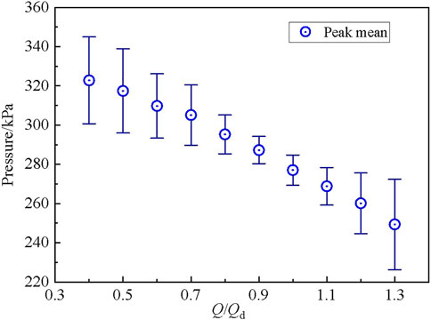
FIGURE 10. Peak difference diagram of pressure pulsation.
Surface Pressure Pulsation Frequency Domain Characteristics of Magnetic Liquid Sealing Film Under Rated Working Conditions
The relationship between the signal amplitude and the frequency change is called the frequency domain. Time domain analysis is an applied mathematical method to study the characteristics of pressure change over time, which mainly studies the amplitude, periodicity and other issues, and cannot well describe the causes of pressure pulsation. However, frequency domain analysis is to obtain the spectral characteristics of pressure pulsation in each working condition by fast Fourier transform, and apply mathematical methods to express the causes of pressure pulsation (Zhang et al., 2020).
Figure 11 is the pressure pulsation frequency domain diagram under the rated working conditions of the centrifugal pump, the abscissa indicates the frequency, and the ordinate coordinate is the pressure pulsation coefficient Cp. As shown in Figure 11, the first main frequency of the surface pressure ripple of the magnetic liquid sealing film under rated conditions is 291 Hz, the second frequency is 582 Hz, and the third main frequency is 2,328 Hz. The centrifugal pump selected for this article has a rotational speed of 2,910 rpm, which can be known according to the axial frequency calculation Eq. 7, and its axis frequency f_n is 48.5 Hz, and according to the leaf frequency calculation Eq. 8, the leaf frequency is 291 Hz. It can be seen that the first main frequency of the surface pressure ripple of the magnetic liquid sealing film is the leaf frequency, the second main frequency is two times the leaf frequency, and the third main frequency is eight times the leaf frequency. Therefore, the main reason for the pressure ripple on the surface of the magnetic liquid sealing film is that the impeller periodically sweeps over the fixed surface of the centrifugal pump.
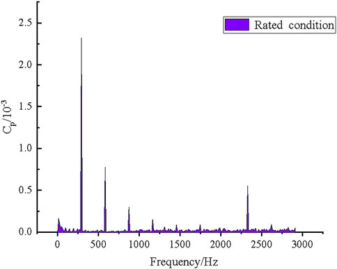
FIGURE 11. Pulsation frequency domain diagram of rated working conditions.
Characteristics of the Surface Pressure Pulsation Frequency Domain of the Magnetic Liquid Sealing Film Under Partial Working Conditions
Figure 12 shows the surface pressure ripple frequency domain diagram of the magnetic liquid sealing film under partial working conditions. It can be seen from the figure that under the working conditions of each flow of the centrifugal pump, the frequency values of the first main frequency, the second main frequency and the third main frequency are the same, so under each flow condition, the main reason for inducing pressure pulsation on the surface of the magnetic liquid sealing film is the periodic sweeping of the fixed surface of the centrifugal pump by the impeller.
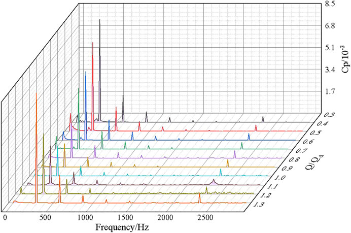
FIGURE 12. Off-mode pulsation frequency domain diagram.
When the centrifugal pump is running at 0.4Qd, there is a broadband frequency at 0–291 Hz, and as the flow rate increases, the broadband phenomenon gradually weakens, reaching a minimum at 1.0Qd, increasing again at 1.1Qd, and then weakening. The reason for this phenomenon is that the centrifugal pump is not fully developed under the operation of small flow conditions, and the internal structure of the centrifugal pump is extremely complex, so its three-dimensional transient flow will cause slight fluctuations in the surface pressure of the magnetic liquid sealing film, and with the increase of the flow rate, the internal fluid flow of the centrifugal pump is fully developed, so the effect on the magnetic liquid sealing film is reduced and the broadband phenomenon is weakened. When the flow rate continues to increase from the rated flow rate, the operating conditions of the centrifugal pump deviate from the design conditions, the fluid in the pump has a more complex non-linear flow, and the phenomenon of liquid return at the outlet of the impeller and the reflection of the liquid at the volute is intensified, and the effect on the surface pressure of the magnetic liquid sealing film increases, so the broadband increases again. When the flow rate is further increased, the fluid development state in the pump is more sufficient than that of the low flow state, and the pressure fluctuation of the magnetic liquid sealing film caused by the non-linear turbulence movement of the fluid in the centrifugal pump has a good inhibitory effect, and the inhibition effect is stronger than the surface pressure of the magnetic liquid sealing film caused by the return of the liquid at the outlet of the impeller and the reflection wave on the wall surface of the volute, so the broadband is reduced again.
When the centrifugal pump is operating at 1.1Qd, there is a broadband at the third main frequency at 2328 Hz. Under the remaining flow conditions, the broadband phenomenon at the third main frequency is not obvious. The broadband at this location is mainly caused by the vortex generated by the return of liquid inside the sealed runner. While the liquid in the pump is transported outward after the impeller is periodically pressurized, the high-pressure fluid is periodically transported to the sealed runner, so there is a return flow and vortex liquid generated by the periodic input of the high-pressure fluid in the sealed runner. Under the action of the vortex, the surface of the magnetic liquid sealing film produces high-frequency pulsation, and the cause of the vortex at this place is related to the periodic rotation of the impeller, so the high frequency at this place is an integer multiple of the leaf frequency, that is, 8 times the leaf frequency.
Conclusion
(1) There is a good periodicity of pressure pulsation on the surface of the magnetic fluid sealing film, which is the time required for a single blade to sweep through the worm tongue. During a rotary cycle of the rotor, the number of reciprocating movements of the magnetic liquid sealing film is the same as the number of rotor blades.
(2) The pressure fluctuation law at different positions on the surface of the magnetic liquid sealing film is very similar under the same flow condition, and the pressure ripple waveform under different flow conditions is different. When working in the rated working condition of the centrifugal pump and its nearby working condition point, the difference between the peak and peak of the surface pressure pulsation of the magnetic liquid sealing film is less than 2000 Pa, and when it deviates from the rated working condition point, the peak-to-peak difference increases by nearly two times.
(3) Under different flow conditions, the surface pressure pulsation frequency domain diagram of the magnetic liquid sealing film is similar, and the first main frequency is the leaf frequency, the second main frequency is two times the leaf frequency, and the third main frequency is eight times the leaf frequency. The surface pressure ripple of the magnetic liquid sealing film has a broadband phenomenon under the working conditions of 0.4–1.0Qd, and the broadband frequency occurs near 0–291 and 2,328 Hz. The broadband phenomenon obtained at 0–291 Hz decreases by increasing the flow rate, increases again when the flow rate is 1.1Qd, and then decreases with the further increase of the flow rate. The third main frequency of the surface pressure pulsation of the magnetic liquid sealing film is mainly caused by the vortex movement caused by the periodic delivery of high-pressure liquid at the outlet of the impeller in the sealing runner.
Data Availability Statement
The original contributions presented in the study are included in the article/Supplementary Material, further inquiries can be directed to the corresponding author.
Author Contributions
KW completed the main writing of the paper, ZL revised the paper, WL and FC provided writing opinions, SY provided experimental guidance, and SP provided software guidance.
Funding
This work was supported by the National Natural Science Foundation of China (Grant No. 52079118), Central leading local (scientific and technological innovation base construction) project XZ202201YD0017C.
Conflict of Interest
Author SP was employed by Huaneng Mingtai Electric Power Co. Ltd.
The remaining authors declare that the research was conducted in the absence of any commercial or financial relationships that could be construed as a potential conflict of interest.
Publisher’s Note
All claims expressed in this article are solely those of the authors and do not necessarily represent those of their affiliated organizations, or those of the publisher, the editors and the reviewers. Any product that may be evaluated in this article, or claim that may be made by its manufacturer, is not guaranteed or endorsed by the publisher.
References
Cao, W., Liu, Y., Dong, J., Niu, Z., and Shi, Y. (2019). Research on Pressure Pulsation Characteristics of Gerotor Pump for Active Vibration Damping System. IEEE Access 7, 116567–116577. doi:10.1109/access.2019.2936489
Chen, Y., Li, D., Zhang, Y., Li, Z., and Zhou, H. (2020). The Influence of the Temperature Rise on the Sealing Performance of the Rotating Magnetic Fluid Seal. IEEE Trans. Magn. 56 (11), 1–10. doi:10.1109/tmag.2020.3023018
Cheng, C., Li, Z., He, F., Wu, S., Zeng, C., Zhang, K., et al. (2022). Influence of Solid–Liquid Two-Phase Flow on Cavitation of Tubular 399 Turbine Blades Under Combined Conditions. Front. Energy Res., 509. doi:10.3389/fenrg.2022.904201
Cheng, C., Li, Z., Peng, S., and Ma, B. (2021). Theoretical Analysis of Entropy Generation at the Blade Interface of a Tubular Turbine under Cooperative Conditions. Front. Energy Res., 763. [J]. doi:10.3389/fenrg.2021.788416
Guo, Z., Xiao, J., Liu, J., and Hu, X. (2019). Comparison of Structured and Unstructured Grids in Marine Controlled Source Electromagnetic Inversions for Offshore Hydrocarbon Exploration. Mar. Petroleum Geol. 100, 204–211. doi:10.1016/j.marpetgeo.2018.11.008
He, Xinzhi., Li, Decai., and Wang, Hujun. (2014). The Effect of Gravity on the Sealing Performance of Magnetic Liquids [J]. J. Vac. Sci. Technol. 34 (11), 1160–1163. doi:10.13922/j.cnki.cjovst.2014.11.05
Hu, Yuxian (2004). Research on Flow Simulation of Pumping Station Inflow and Outflow Channel Based on FLUENT Software. Wuhan, China: Wuhan University. [D].
Jibin Zou, J., Jiming Zou, J., and Jianhui Hu, J. (2003). Design and Pressure Control of High-Pressure Differential Magnetic Fluid Seals. IEEE Trans. Magn. 39 (5), 2651–2653. doi:10.1109/tmag.2003.815543
Jin, En (2020). Research on the Influence of Elbow Inflow on the Internal Flow of Centrifugal Pump. Xi'an, China: Xi'an University of Technology. [D].
Li, Decai., Hong, Jianping., and Yang, Qingxin. (2002). Research on Magnetic Fluid Sealing of Dry Roots Vacuum Pump. Vac. Sci. Technol. 2002 (04), 78–81. [J]. doi:10.13922/j.cnki.cjovst.2002.04.019
Li, W., Li, Z., Qin, Z., Yan, S., Wang, Z., Peng, S., et al. (2022). Influence of the Solution pH on the Design of a Hydro-Mechanical Magneto-Hydraulic Sealing Device. Eng. Fail. Anal. 135, 106091. [J]. doi:10.1016/j.engfailanal.2022.106091
Li, W., Li, Z., Wang, Z., Wu, F., Xu, L., and Peng, S. (2021a). Turbulence Intensity Characteristics of a Magnetoliquid Seal Interface in a Liquid Environment. Coatings 11 (11), 1333. doi:10.3390/coatings11111333
Li, Z., Li, W., Li, W., Wang, Q., Xiang, R., Cheng, J., et al. (2021b). Effects of Medium Fluid Cavitation on Fluctuation Characteristics of Magnetic Fluid Seal Interface in Agricultural Centrifugal Pump. Int. J. Agric. Biol. Eng. 14 (6), 85–92. doi:10.25165/j.ijabe.20211406.6718
Liu, T., Cheng, Y., and Yang, Z. (2005). Design Optimization of Seal Structure for Sealing Liquid by Magnetic Fluids. J. Magnetism Magnetic Mater. 289, 411–414. doi:10.1016/j.jmmm.2004.11.116
Lu, Jiaxing (2017). Study on Cavitation-Induced Unsteady Dynamic Characteristics and Mechanism of Centrifugal Pump. Zhenjiang, China: Jiangsu University. [D].
Peng, Tao (2021). Centrifugal Pump Mechanical Seal Leakage Phenomenon and Maintenance Countermeasures Research. Mod. Manu. Tech. and Equi. 57, 158–159. doi:10.16107/j.cnki.mmte.2021.0480
Qian, Jiguo., and Yang, Zhiyi. (2008). Stability Analysis of Liquid-Liquid Interface of Magnetic Hydraulic Seals. Fluid Mach. 36 (12), 21–23. doi:10.3969/j.issn.1005-0329.2008.12.005
Ren, Z. A., Hao, D., and Xie, H. J. (2009). Several Turbulence Models and Their Applications in FLUENT. Chem. Equi. Tech. 30, 38–40+44. doi:10.16759/j.cnki.issn.1007-7251.2009.02.005
Szczęch, M. (2020). Magnetic Fluid Seal Critical Pressure Calculation Based on Numerical Simulations. Simulation 96 (4), 403–413. doi:10.1177/0037549719885168
Szczech, M. (2018). Experimental Study on the Pressure Distribution Mechanism Among Stages of the Magnetic Fluid Seal. IEEE Trans. Magn. 54 (6), 1–7. doi:10.1109/tmag.2018.2816567
Wang, Yaohua (2004). Numerical Simulation Design of High Temperature Magnetic Fluid Seal and its Application Research. Wuhan, China: Wuhan University of Technology. [D].
Winslow, P., Pellegrino, S., and Sharma, S. B. (2010). Multi-objective Optimization of Free-form Grid Structures[J]. Struct. Multidiscip. Optim. 40 (1), 257–269. doi:10.1007/s00158-009-0358-4
Xu, Bing. (2013). Rui Yannian. Research on Mechanical and Magnetic Fluid Composite Dynamic Sealing Technology of Pressure Reactor Stirring Shaft. Mech. Des. 30 (04), 6–10. [J]. doi:10.13841/j.cnki.jxsj.2013.04.012
Xu, Zhaohui (2004). Study on Three-Dimensional Flow of Full Flow Channel in High-Speed Centrifugal Pump and its Fluid-Induced Pressure Pulsation. Beijing, China: Tsinghua University. [D].
Xu, Zhenshi., Fan, Jun., and Xie, Yuanjian. (2010). Introduction to Modern Sealing Technology. Mod. Manuf. Technol. Equip. 2010 (01), 7–9. doi:10.16107/j.cnki.mmte.2010.01.008
Zeng, H., Li, Z., Li, D., Chen, H., and Li, Z. (2022). Vortex Distribution and Energy Loss in S-Shaped Region of Pump Turbine. Front. Energy Res. 10, 904202.
Zhang, Chenghua., You, Jianfeng., Tai, Rong., Wang, Xi., Liu, Ying., and Cheng, Yongguang. (2020). CFD Simulation of Pressure Pulsation during Runaway Process of Water Pump, Turbine, Water Pump and Runaway. J. Hydroelectr. Power Generation 39 (04), 62–72. doi:10.11660/slfdxb.20200407
Zhang, H., Li, D., Wang, Q., and Zhang, Z. (2013). Theoretical Analysis and Experimental Study on Breakaway Torque of Large-Diameter Magnetic Liquid Seal at Low Temperature. Chin. J. Mech. Eng. 26 (4), 695–700. doi:10.3901/cjme.2013.04.695
Zhao, Guowei., Chi, Changqing., Wang, Zhishan., and Wang, Guangzhen. (2001). Flow Field Analysis of Magnetic Fluid Seal on High-Speed Shaft. J. Beihang Univ. 27 (06), 628–631. [J]. doi:10.13700/j.1001-5965.2001.06.003
Zhou, J., Fan, H., and Shao, C. (2016). Experimental Study on the Hydrodynamic Lubrication Characteristics of Magnetofluid Film in a Spiral Groove Mechanical Seal. Tribol. Int. 95, 192–198. doi:10.1016/j.triboint.2015.11.018
Keywords: centrifugal pump, magnetic liquid, seal, pressure pulsation, numerical calculations
Citation: Li Z, Wang K, Li W, Yan S, Chen F and Peng S (2022) Analysis of Surface Pressure Pulsation Characteristics of Centrifugal Pump Magnetic Liquid Sealing Film. Front. Energy Res. 10:937299. doi: 10.3389/fenrg.2022.937299
Received: 06 May 2022; Accepted: 09 June 2022;
Published: 28 June 2022.
Edited by:
Kan Kan, College of Energy and Electrical Engineering, ChinaReviewed by:
Qiang Gao, University of Minnesota Twin Cities, United StatesXianbei Huang, Yangzhou University, China
Copyright © 2022 Li, Wang, Li, Yan, Chen and Peng. This is an open-access article distributed under the terms of the Creative Commons Attribution License (CC BY). The use, distribution or reproduction in other forums is permitted, provided the original author(s) and the copyright owner(s) are credited and that the original publication in this journal is cited, in accordance with accepted academic practice. No use, distribution or reproduction is permitted which does not comply with these terms.
*Correspondence: Zhenggui Li, bHpoZ3VpQG1haWwueGh1LmVkdS5jbg==