 Luigi Mercatali
 Gianfranco Huaccho
 Victor-Hugo Sanchez-Espinoza
- Karlsruhe Institute of Technology, Institute for Neutron Physics and Reactor Technology, Germany
Typical design basis accidents such as the control Rod Ejection Accident (REA) will need to be evaluated during the safety analysis in support the licensing processes for most of the current Small Modular Reactors (SMRs) designs. In this paper a study related to the neutronic and thermal-hydraulic coupled modelling of a REA transient for a boron-free SMART-like core at different fidelity levels is presented. Two different solutions for the core at hot zero power state (HZP) are provided; the first one is based on the standard nodal two-steps approach using the diffusion approximation and the second one is characterized by a more accurate high-fidelity scheme based on Monte Carlo neutronics coupled to subchannel-level thermal-hydraulics allowing performing full core pin-by-pin transient analysis. In the paper the details of the two different modelling approaches are presented and the corresponding results are compared one to each other, allowing on one side to verify the results of the high-fidelity modelling against a standard nodal-based solution and on the other side to highlight the added value when using a better resolution which allows to compute safety parameters at the local level with the consequent possibility to reduce the safety margins.
1 Introduction
Due to their reduced core sizes, Small Modular Reactors (SMRs) typically exhibit larger heterogeneities and gradients in the neutron flux distribution with respect to traditional large Light Water Reactors (LWRs) (Jose' & Reyes, 2017). This can be partly countered with aggressive profiling of the fuel loading; however the significance of the core boundary fuel assemblies (FAs) that exhibit the steepest internal flux gradients is an inescapable fact as the boundary FAs make up a larger proportion of the reactor core in small cores when compared to the large ones. On one hand, the state-of-the-art LWR analysis tools are usually based on an assembly-level (nodal) coupling of the different physics and may face challenges in resolving local intra-assembly details of the coupled problem. On the other hand, advanced low-order methods with rod-level resolved coupled physics are already available (although beyond the state-of-the-art) and trade the fast runtimes of the traditional tools with an increased accuracy in the prediction of rod-level safety parameters. High-fidelity methods for reactor analysis are becoming more and more attractive due to their potential to cope with the more strict requirements of the nuclear safety standards and with the goals of the reactor designers’ and operators’ to reduce safety margins for improved commercial performances. The use of these advanced simulation methodologies at high resolution is possible nowadays due to availability of HPC architectures at a relatively low cost. As a part of this trend, novel high-fidelity methods have been recently developed that couple continuous energy Monte Carlo neutronics tools with sub-channel thermal hydraulics solvers (Sanchez-Espinoza, et al., 2021). These beyond the state-of-the-art solvers have the drawback of the significant runtime, but due to their fewer approximations on the core physics when compared with the low-order tools, they are used to provide reference solutions for those cases where little or no experimental data are available. In fact, one of the challenges in the licensing of new SMRs concepts is the lack of operational data from the concepts that could be used for validating the day-to-day reactor analysis tools used in the deterministic safety analyses.
In this paper, the simulation of a Rod Ejection Accident (REA) in a SMR core is presented and discussed. This work was performed within the framework of the EU H2020 McSAFER Project (Sanchez & al., 2021) whose main objective is to advance the safety research for SMRs by combining safety-relevant thermal-hydraulic experiments with advanced numerical simulations at different spatial resolution levels.
The core design considered in this study is the KSMR core developed at the Karlsruhe Institute of Technology (KIT), based on the SMART concept (Lee & Zee, 2003) and optimized to produce 330 MWth (Alzaben, et al., 2019). The selected transient is assumed to initiate at Hot Zero Power condition, resulting in a rapid reactivity insertion that may challenge the fuel-cladding integrity. In this study two different solutions of the selected transient are presented. Firstly, the transient has been analyzed by means of the standard nodal diffusion two-steps approach using the PARCS code and this will provide the “state-of-the-art-solution” against which any new solver will be compared to in order to demonstrate the new capability regarding the prediction capability of the safety parameters. In a second step, the transient has been modeled with the high-fidelity coupled code Serpent2/SCF allowing performing pin-by-pin transient simulations by coupling neutronics and thermal-hydraulics at the sub-channel level.
2 The KSMR core
The concept of boron-free PWRs that has been proposed several decades ago (Alex, et al., 1986) is nowadays regaining popularity, especially within the framework of water cooled SMRs, due to the availability of advanced designs for burnable absorbers (BA) capable of guarantee enough small excess reactivity without compromising the neutronic and safety performances (Yahya & Kim, 2017) (Kim, et al., 2016) (Merwe & Hah, 2018).
The KSMR core is the results of an innovative boron-free core design developed at KIT that fits into a generic SMART-like SMR cooled by light water and that incorporates well established LWRs technologies with regard to FAs design and type of materials (Alzaben, et al., 2019). It is optimized to produce 330 MWth and loaded with 57 fuel assemblies (FAs) (Figure 1). The soluble-boron-free operation concept has been adopted in order to have a higher moderator temperature coefficient and also to exclude the possibility of a boron dilution accident. The basic FA design is based on a 17 × 17 rods pattern containing 24 guide tubes and a central instrumentation tube. Each FA has a different number of BA rods (either 20 or 24) depending on their position inside the core (Figure 1). These BA are made of Al2O3 mixed with B4C and allow the reduction of the HFP excess reactivity at the beginning of life as well as the core peaking power. The fuel pins are cladded with Zr-4 and their enrichment is lower than 5%. In order for the radial and axial peaking factors to be as smooth as possible, six different types of FAs have been conceived with different radial and axial variation of enrichment and BAs (Figure 1). The central FA is the one with the lowest enrichment and the FAs at the periphery do not contain any BAs but they have dummy rods filled with Al2O3. The final optimized core design configuration together with the axial enrichment distribution is shown in Figure 1.
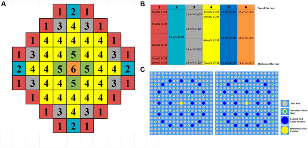
FIGURE 1. KSMR optimized radial core loading (A); Axial core enrichment distribution (B); (C) FA layout with 20 (left) and 24 (right) burnable poison rods.
As far as the control rods (CRs), they were designed to provide fast reactivity insertion as well as reactivity adjustment as required for power manoeuvring and transient compensation. Figure 2 shows the CRs configuration that satisfies these goals. The final core design (Figure 1) has 53 rodded FAs divided in two banks, namely, for regulation and shutdown. All the additional details of the KSMR core design can be found in (Alzaben, et al., 2019).
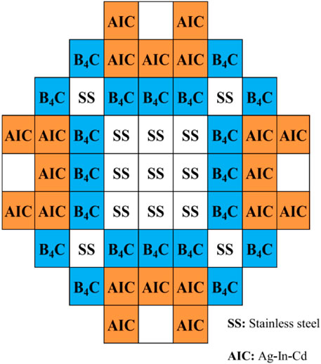
FIGURE 2. KSMR control rods configuration.
3 The REA transient scenario
The transient scenario considered in this study consists in a Rod Ejection Accident (REA) (Szilard, et al., 2011), (Abdo, 2014), (Khalil, 2011), (Kim, et al., 2011). This a typical design basis event where a CR assembly is rapidly completely ejected out of the core due to a failure of the Control Rod Mechanism (CRDM) housing structure (OECD/NEA, 2010). In safety analysis, the case studied for this type of scenario is the one corresponding to the ejection of the rod with the highest reactivity worth. In particular, in our analysis this is investigated at the beginning of cycle (BOC) and at Hot Zero Power (HZP) conditions. The initial core configuration for the REA transient is shown in Figure 3 and the initial conditions are summarized in Table 1. In this arrangement, all the boron carbide (B4C) control rods are fully extracted whereas the remaining ones are fully inserted. This configuration is not in a critical state and as a consequence in the solutions presented in this paper the fission source is accordingly normalized. The reason for choosing this type of condition is because in this way the most reactive CR to be ejected is worth approximately 1.5$, thus enabling the possibility of studying a super-prompt critical transient with an asymmetrical power distribution.
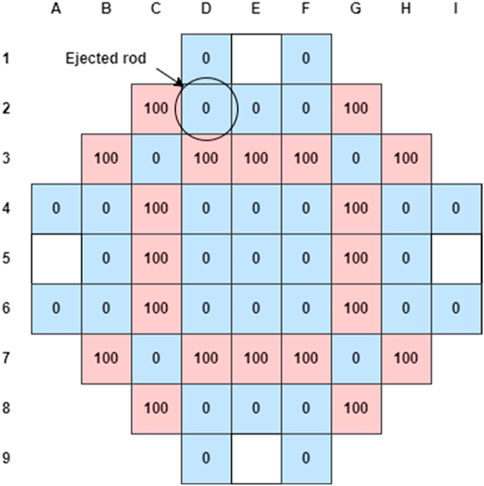
FIGURE 3. Initial CRs configuration for the REA transient (”100” indicates CR completely withdrawn and “0” indicates CR completely inserted. White-boxes mean there is no CR at that position).
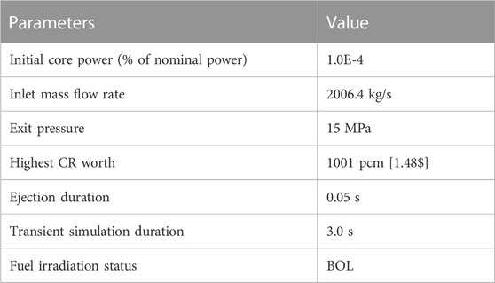
TABLE 1. Initial conditions for the REA scenario at HZP.
4 The PARCS/Subchanflow nodal solution
In this study the solution of the REA transient at the nodal level has been performed by means of the PARCS code (Downar, 2017) coupled with the Subchanflow code (U. Imke, U.; V.H. Sanchez and al, 2012).
PARCS is a three-dimensional core solver able to simulate static and dynamic reactor conditions in both Cartesian and Hexagonal geometries using either the multi-group diffusion approximation or the SP3 simplified transport formulation. In particular, for the PARCS simulations carried out in this work, the hybrid ANM/NEM nodal scheme has been used, which is based on the finite difference method in the x and y directions and on the well-established nodal expansion method in the z direction (Lee, et al., 2004).
Subchanflow (SCF) is a four equations (mass, energy, axial and lateral momentum) subchannel thermal-hydraulic code developed at KIT. It can be used for both static and transient simulations and is widely adopted and validated for LWRs applications.
In order to generate the PARCS solution of the REA transient, the first step consists in the transport calculation at the lattice level in order to produce the multi-group homogenized cross sections. In our approach this task has been performed using the Serpent2 Monte Carlo code (J. Leppänen et al., 2015).
Detailed Serpent 2 2D FA models with explicit pin-wise geometrical description have been created taking into consideration the variation of the material compositions as a function of the core height. Subsequently, spatial homogenization and energy-group condensation have been carried-out for each model using reflective boundary conditions (BCs) and a two-group energy structure with the typical cut-off at 0.625 eV. For each model, the homogenized cross-sections have been generated for branch variations originating from the variation of the moderator temperature, the fuel temperature and the CRs position (Table 2). As far as the statistics in the Monte Carlo simulations, for each branch a total of 109 active particle histories divided into 2000 active cycles are used with 500 inactive cycles in order to make sure that the fission source is converged. The main reason for such a large number of active neutron histories is the need to reduce the statistical noise associated with the generation of the group-wise form functions that are subsequently used in PARCS for the pin powers reconstruction.
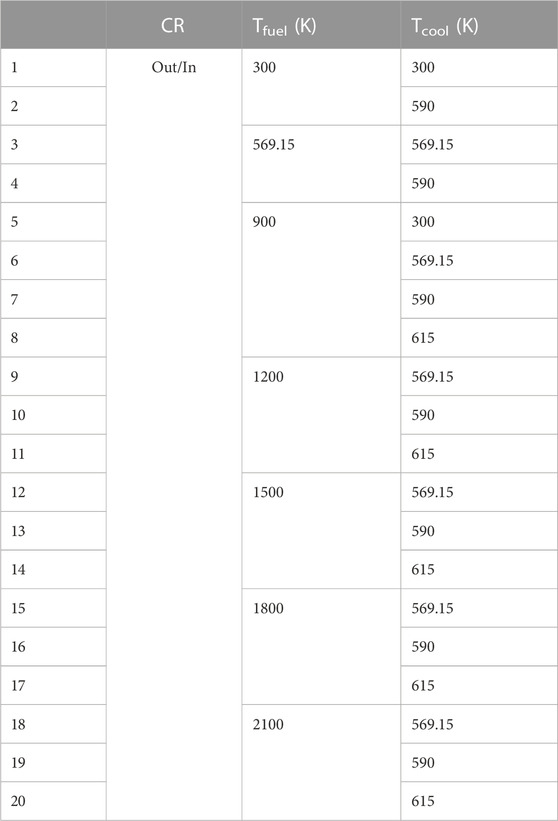
TABLE 2. Branch variations for the homogenized XSs generation.
The group constants for the top and bottom axial reflectors have been produced according to the same two group-structure used for the FAs energy condensation through a Serpent2 3D FA model using reflective BCs in the radial direction and black BCs in the axial direction. In the spatial homogenization, for the top axial reflector the average core outlet temperature is considered while for the bottom part the coolant conditions are set to the core inlet temperature. For the radial reflector, a Serpent2 3D full core model has been considered, in which all regions are set to the average core temperatures for fuel and coolant. As shown in Figure 4, each node in which the radial reflector is divided is adjacent to a FA. Each homogenized region has the same dimension of a FA where the core baffle is homogenized with the coolant around. As a consequence, nine reflector group constants data are generated for each unique position in a quarter of the core (Figure 4). Therefore, with this methodology it is possible to get the detailed spectrum used in the reflector energy-group condensation process.
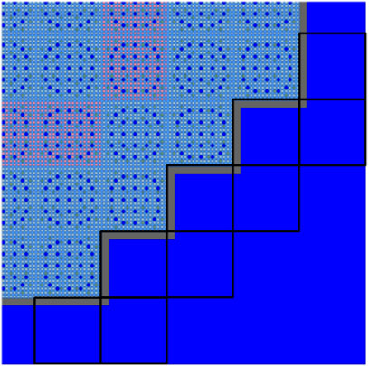
FIGURE 4. Model used for the reflector homogenized XSs generation (1/4 of the full core).
After having generated the 2-group XSs with the approach described above, these are subsequently converted into the PARCS Macroscopic XS (PMAXS) format via the GenPMAXS code (Ward, et al., 2016) in order to be used for the solution of the REA transient.
The coupling between PARCS and SCF has been implemented at KIT through the ICoCo interface (salome-platform, 2007). The main advantage of this coupling approach is that it does not interfere with the syntax of the codes, i.e., inputs have to be made for PARCS and SCF as usual. A MED mesh, as available in the SALOME platform (salome-platform, 2007) is generated using a MED pre-processor (Garcia, 2019a), for the codes to store the variables fields, and, via ICoCo routines, both codes communicate using get and set functions for fields and time step definition.
The core neutronic model consists radially in one node per FA or reflector element (it may contain sub-nodes) and has an axial discretization of 27 elements: 20 for the active height, 3 for the bottom reflector and 4 for the upper reflector. In SCF only the active height has been modelled with the same radial and axial discretization as the neutronic model. Each FA has been modelled as a single channel with a representative rod considering cross flow between neighbour nodes.
The transient calculation for the REA scenario was performed with an explicit time scheme between neutronics and TH with a time step of 0.0005 s without relaxation factors applied during the feedback fields’ exchange. Given that the core is not initially in a critical configuration, the source has been normalized at the beginning of the transient calculations.
5 The Serpent2/subchanflow high-fidelity solution
As an alternative to the standard two-steps method usually adopted in reactor safety analysis, an increasing effort is currently being observed in the nuclear community to develop high accurate multi-physics approaches based both on high-fidelity Monte Carlo and deterministic codes coupled with subchannel thermal hydraulic codes. This trend is also driven by large and cheap HPC-clusters for massive parallel computing. In this context and within the framework of the EU H2020 McSAFE Project (Sanchez-Espinoza, et al., 2021), several attempts have been undertaken to develop Monte Carlo-based high-fidelity coupling schemes capable to simulate pin-by-pin full cores’ behaviour both at steady state but also with burnup and time dependent capabilities. In particular, a new beyond state-of-the-art master-slave coupled code was developed based on Serpent2 (as master) and SCF (as slave) (Ferraro et al., 2020a; Ferraro et al., 2020b; Ferraro et al., 2020c). This scheme is strongly based on the use of the advanced capabilities available in the two codes, including the possibility to handle variable temperatures and density profiles in a convenient way for coupled calculations through superimposed meshes (namely, Multiphysics Interface Files (IFC)) and the Serpent2 capability to model time dependent geometry transformations (such as CR movements) as well as prompt and delayed neutrons. The fields’ exchange (TH parameters and fission power) is carried out through the values from this IFC, where proper mapping files are included to consider the FAs’ position. In the developed Serpent2/SCF coupling, on one side a number of so called open door functions are offered by Serpent2 which allow managing the typical issues of a coupled scheme (i.e., initialization, iteration, termination, deallocation, etc.) and on the other side SCF is used as a shared library, where ad–hoc high–level functions are used (Garcia, 2019b). In order to connect these two aspects, specific routines were implemented to properly consider their interaction. Thanks to this type of implementation, both Serpent2 and SCF are independently maintainable and the tool can be easily updated with the next releases of the codes.
As far as for the transient capabilities of the Serpent2/SCF coupling, the standard approach for time-dependent Monte Carlo is used, in which a complex number of different issues need to be taken into consideration. In general, since the position and the energy of any neutron at each interaction point are known, generally these simulations are performed as an external source with a proper time steps discretization and a population control between each time step (Leppänen, 2013). One of the most important challenges is also the large difference in the time scales between the prompt neutrons and the delayed neutrons precursors which need also to be considered. In order to cope with this problem, the approach adopted in Serpent2 (as well as in other MC codes) is to track the precursors’ producing the delayed neutrons instead of directly sampling the delayed neutron from fission (Valtavirta, 2016). As a consequence, two different external sources have to be taken into consideration, namely, the one that can be identified with the so called live neutrons and a second one representative of the precursors. In order to properly generate these two sources a prior criticality calculation need to be performed. Therefore, Serpent2 time-dependent calculations are based on a two-steps approach, as shown in Figure 5.
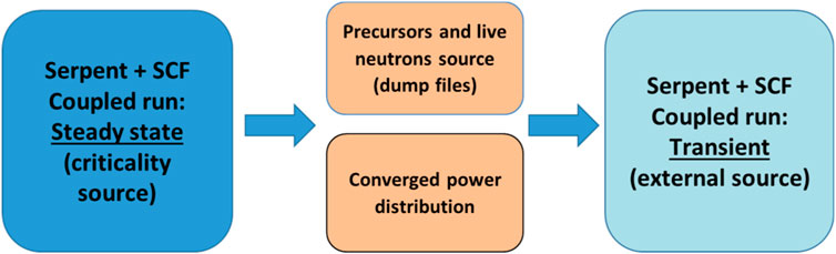
FIGURE 5. Transient two-step approach for coupled calculations.
Since SCF has already time-dependent capabilities by its own (Imke et al., 2012; .; Sanchez and al, 2012), from the TH point of view of the actual coupling approach, the main issue is to properly update the power fields at each time bin. From the neutronic side, in Serpent2 a time-dependent calculation is carried out by tallying the fission power at each time bin, a population control for live neutrons and precursors is applied and the IFC TH fields are updated using the SCF’s results. In order to generate the two initial source distributions, a steady-state criticality calculation is performed in which the positions of live neutrons and delayed neutron precursors are recorded for the converged steady state critical configuration into dedicated files. In the second step the actual transient calculation is performed based on the values stored in the previous step. Moreover, the converged power from the criticality coupled calculation in the first step is used for an initial SCF run in order to consider the right TH fields for the first time step.
5.1 The KSMR models developed
5.1.1 Serpent2 neutronic model
The coupling approach described above together with the capabilities of the Serpent2 code to consider time-dependent geometry transformations (as for example, CR movements) allow the modelling of the REA-type scenarios.
A detailed Serpent2 3D pin-by-pin model has been developed (Figure 6), making up to 16473 fuel pins. As far as the cross section data, the ENDF-B/VII library has been used for the simulations, containing eight families of precursors’ groups. Independent IFC fuel pin-by-pin and coolant subchannel-by-subchannel with a Cartesian mesh covering the active core axial length with 20 layers have been used, to be further coupled with the TH fields. As far as the neutron histories, 107 neutrons in 100 batches have been used in Serpent2 for the transient analysis, while 105 are used for the source generation. As far as the convergence criteria for the initial steady-state and source generation, 5 pcm has been used for reactivity, 1°C for fuel temperature, 1°C for coolant temperature and 0.01 g/cm3 for coolant density.
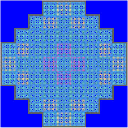
FIGURE 6. Serpent2 full pin-by-pin model of the KSMR core (configuration with all CRs extracted).
5.1.2 SUBCHANFLOW TH model
As far as the TH model in SCF, a coolant-centered subchannels model with 20 axial layers has been used (Figure 7) and for each FA 18 × 18 channels were considered, making a total of 18468 channels.
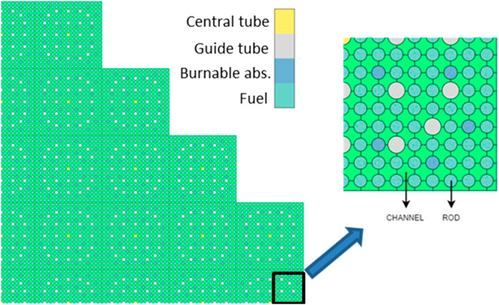
FIGURE 7. SCF pin-by-pin subchannel centered model (1/4 of the core).
5.2 Running environment
As far as the computational resources used, the coupled Serpent2/SCF simulations were run in the Horeka HPC cluster of KIT (Horeka, 2022). The Serpent2 calculations were performed using the MPI-OMP approach while the SCF code was executed sequentially. In particular, 20 nodes of 150 CPUs each (Intel Xeon Platinum 8368) have been utilized. The total running time to simulate 3s of REA transient was 3660 min.
6 Discussion of results
6.1 Core reactivity and power
Beginning from the aforementioned initial condition the CR is ejected in 0.05s from fully inserted to fully extracted conditions. Given that the rod worth is over 1$ the system quickly becomes super prompt critical (Figure 8) and therefore the fission chain can be sustained only by prompt neutrons with generation times of a few microseconds. In this way, an extremely rapid exponential power increase is observed (Figure 9). The fuel temperature increase first and the moderator density decrease later will counteract this reactivity with some delay due to the energy deposition mechanisms until it reaches a value under 1$. At this point, the fission chain is no longer sustained only by prompt neutrons but it will also need the delayed neutrons production. This will cause the power to decrease until the generation of delayed neutrons is strong enough to sustain the fission chain again. An agreement within 3.9% on the maximum reactivity value computed by PARCS/SCF and Serpent2/SCF has been found (Table 3). Also, according to the nodal solution a power peak of 48.35 times the nominal power (330 MWth) is achieved at t = 0.1645 s when the reactivity crosses under 1$ as observed in Figure 8. The power peak calculated by Serpent/SCF was found to be ∼25% lower with respect to PARCS/SCF solution and the peak time is observed at t = 0.195s (time-bin 1.192s–0.198s). The nodal and pin-by-pin axially integrated pin power maps at peak time are show in Figure 10. In order to have an estimation of the statistical uncertainty associated to the pin power values computed with the high-fidelity solution, the relative statistical error distributions at different time bins and the relative statistical error core map for axial cell 11 (from 1.0 to 1.1 m) at the peak time bin (0.192s–0.198s) are shown in Figure 11. In particular, at peak time, a root-mean-square (RMS) of 4.4% has been achieved.
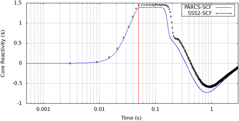
FIGURE 8. REA reactivity evolution in time (the red line marks when the CR is fully extracted, 3-sigmas are considered for power error bars, points are plotted in the middle of the time bin).
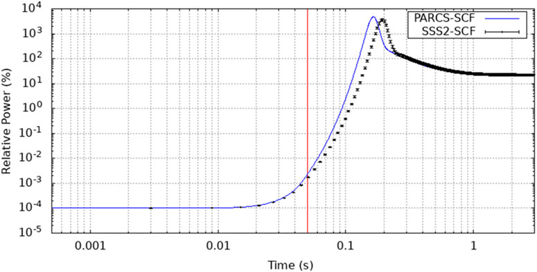
FIGURE 9. REA relative power evolution in time (the red line marks when the CR is fully extracted).
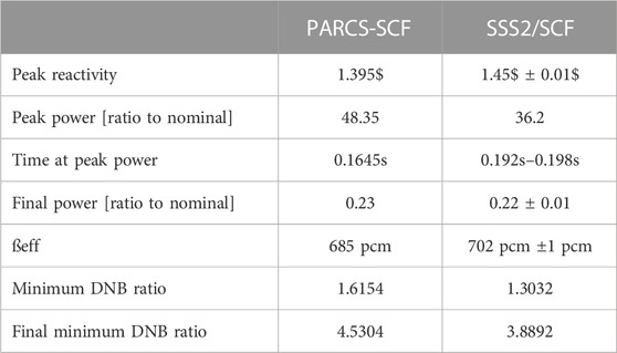
TABLE 3. Maximum values reached during the REA transient.
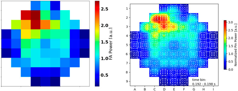
FIGURE 10. PARCS/SCF (left) and Serpent2/SCF (right) axially integrated (normalized) pin power map for the REA scenario at peak time.
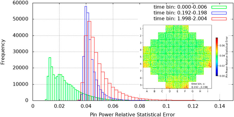
FIGURE 11. Pin power relative statistical error distribution and pin power relative statistical error core map for axial cell 11 (from 1.0 to 1.1 m) at the peak time bin (0.192s–0.198s).
Fuel temperature will continue to rise as well as the coolant density will continue to decrease with the rate of the power from some instant before and, thus, the effect in the reactivity will be higher than the instantaneous power. As shown in Figure 8 the reactivity becomes negative and subsequently starts to increase once the coolant and fuel decreases in temperature. The system will continue to evolve until the reactivity reaches the zero value and a new steady state will be achieved but this is out of the scope of the transient’s duration analysed in our study (3s). An excellent agreement on the final power levels after 3 s of REA transient has also been found (Table 3).
6.2 Temperatures
The fuel temperature starts to increase following the power excursion and it is the first parameter inserting a negative reactivity into the core and thus counteracting the supercritical state. In Figure 12 the evolution in time during the transient of the maximum fuel centreline temperature is shown. The peak values for fuel temperatures provided by the high-fidelity solutions were found to be 107 K higher with respect to the ones provided by the nodal solution. However, maximum fuel temperature values for both PARCS/SCF and Serpent/SCF are well below the UO2 melting point (∼2800°C) (Carbajo, et al., 2001). Moreover, the pin/subchannel Serpent/SCF core model allows the knowledge of the hottest pin rod during the transient. For the pin rods SCF calculates temperatures at the centre, outer or external radius as well as an average value inside the pin. All maximum values were found to be in two pin rods belonging to the same FA in position C2 (Table 4). These pins are the (ROD (14,5,10)) and ROD (13,4,11), they are next to each other and close to a guide tube filled with water which improves the neutron moderation and fission reactions (Figure 13). The nodal solution provides the hottest pin rod to be in the FA positioned in D2.
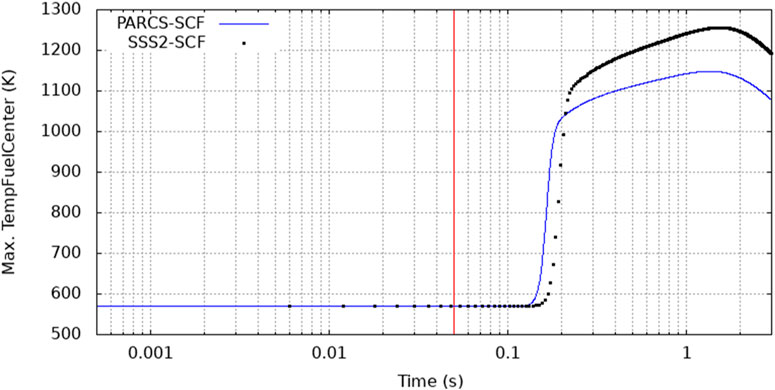
FIGURE 12. Evolution in time of the maximum fuel centreline temperature.
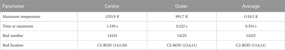
TABLE 4. Maximum values for centre, outer and average fuel temperatures (values reached at different times during the transient).
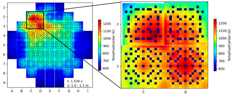
FIGURE 13. Fuel centreline temperature distribution in axial zone 11 (1.0–1.1 m): KSMR full core map (left), four FAs in the hot spot near the CR ejection position (right).
According to Serpent/SCF, the highest coolant temperature is found in FA-C2 (channel 15961 and 15980) starting at t = 0.954 s up to t = 1.140 s. The high-fidelity solution shows that in this case the saturation temperature (i.e. 615°K at 15 MPa) is reached in two channels next to the hottest fuel pin rods (Figure 14), while the PARCS/SCF solution provides lower values (Figure 15). Axially maximum coolant temperatures are at the exit of the channel. A temperature map distribution at peak time is shown in Figure 16.
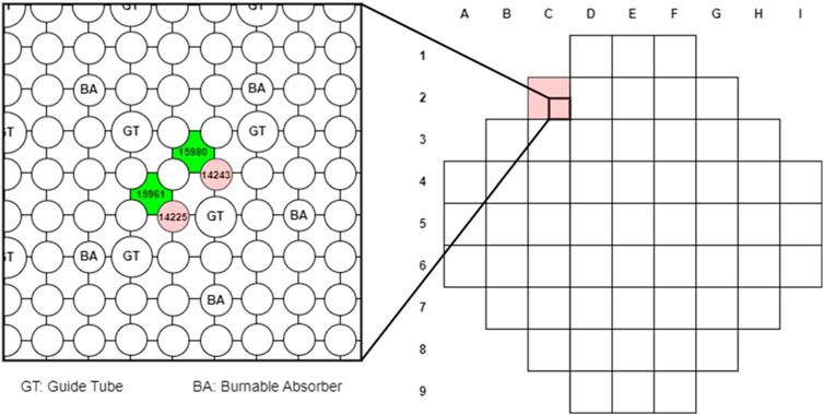
FIGURE 14. KSMR core configuration with highest temperature during the REA transient (C2 FA) (right). Pins and channels hottest points in C2 FA (left).
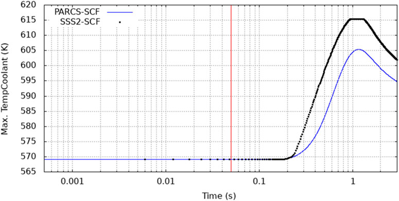
FIGURE 15. REA maximum coolant evolution in time.

FIGURE 16. Coolant temperature map (t = 1.002) at exit channels.
The maximum inner and outer cladding temperatures evolutions during the transient are presented in Figure 17 and Figure 18. The maximum temperature is reached in FA-D3 and FA-C2 (rod 14225) for the PARCS/SCF and Serpent2/SCF solutions respectively and in any case the peak values were found to be far below the Zr-4 cladding melting point (1480°C) (IAEA, 2003).
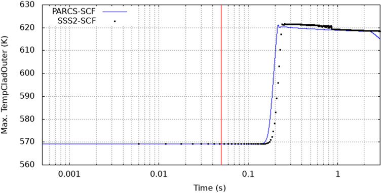
FIGURE 17. REA maximum cladding inner temperature evolution in time.
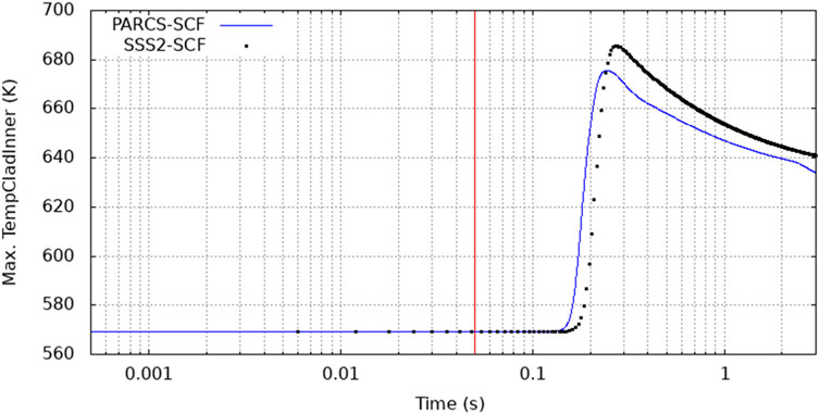
FIGURE 18. REA maximum cladding outer temperature evolution in time.
6.3 Departure from nucleate boiling (DNB)
The results of the departure from nucleate boiling ratio (DNB) are summarized in Table 5; Figure 19. The minimum DNB value estimated with the Serpent2/SCF coupling has been found in FA-D2 at t = 0.246s of the REA transient, while the minimum DNB predicted by PARCS/SCF occurs in the same D2 position and is higher by about 24%. In Figure 20 the DNB ratio sequence in time on the compromise region due to the REA transient (axial zone 11 of C2, D2, C3, and D3 FAs) is presented. Results for the inverse DNB ratio are given for a better visibility of the minimum values. One can observe that only a few amounts of fuel rods are compromised at t = 0.246 and this number is going to increase with the progression of the transient. This is an example of the type of interesting information that one can get when using a very detailed resolution in the modeling, which can in principle allow to investigate safety related parameters at the local level. This eventually can lead to cope with one of the most important needs of the reactor operators and licensing authorities, namely, the reduction of the safety margins.
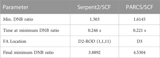
TABLE 5. DNB ratio results.
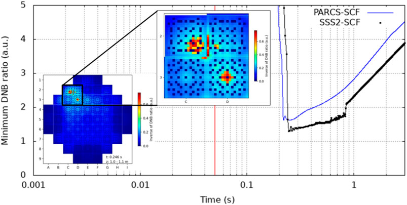
FIGURE 19. Minimum DNB ratio during transient at pin level detail. A DNB ratio core map is presented at time where minimum value was found (t = 0.246s), minimum DNB ratio was found in the FA D2 (first pin fuel rod starting from bottom left in axial cell 11 (1.0–1.1 m)).
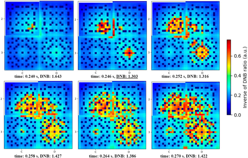
FIGURE 20. Inverse of DNB ratio time-sequence (minimum value found at 0.246 s of the transient).
7 Conclusion
In this study the modeling of a reactivity insertion accident for the KSMR boron-free core has been presented. This type of investigation is of relevance as part of the deterministic safety analysis in support to the licensing process for most of the future SMRs. The scenario considered, representative of a super-prompt critical design basis accident, has been simulated at two different fidelity levels, namely, the classical two-steps diffusion based nodal approach and a more accurate high-fidelity approach based on the Serpent2/SCF coupling tool. The exercise represents the first verification of the nodal PARCS/SCF solution against a Serpent2/SCF high-fidelity solution. Based on the comparison of key parameters predicted by both solution approaches it can be concluded that the nodal solution is not conservative. It means that the high-fidelity solution predicts a higher local power peak, higher cladding temperature and lower MDNBR compared to the one of the nodal approach. Both solutions predict similar evolution of the total power, reactivity, cladding temperature but the timing is not the same. The high quality of the PARCS/SCF results with the pin power reconstruction (PPR) approach is achieved through the use of detailed Serpent2 FAs and core models for the fuel’s and reflector’s group constants generation including discontinuity factors and form functions for the PPR-approach. It is worth to highlight that the Serpent2/SCF simulation allows identifying the rod with the highest power and the subchannel with the highest coolant temperature and the local respective safety parameters, which cannot be obtained by a nodal solution. From a safety analysis point of view, the investigations allow to conclude that the integrity of the fuel rod cladding is not challenged during the REA (fuel and cladding peak temperatures are below the melting points). Further investigations including a more realistic description of the irradiated fuel by incorporating a fuel performance code in the coupled system will allow us to quantify the impact of burnup on the final results for end of cycle (EOC) conditions.
Data availability statement
The raw data supporting the conclusion of this article will be made available by the authors, without undue reservation.
Author contributions
LM: Writing original draft, Writing review and editing, Models development, Methodology, Conceptualization and comparison of the two numerical solutions. GH: Writing review, Software, Methodology, Models development, Simulations. V-HS: Writing review and editing, Funding acquisition, Project administration, Supervision.
Funding
This work has received funding from the Euratom research and training program 2019–2020 under grant agreement No 945063 H2020 McSAFER project and the NUSAFE program of the Karlsruhe Institute of Technology (KIT). This work was performed on the Horeka supercomputer funded by the Ministry of Science, Research and Arts Baden-Württemberg and by the General Federal Ministry of Education and Research.
Conflict of interest
The authors declare that the research was conducted in the absence of any commercial or financial relationships that could be construed as a potential conflict of interest.
Publisher’s note
All claims expressed in this article are solely those of the authors and do not necessarily represent those of their affiliated organizations, or those of the publisher, the editors and the reviewers. Any product that may be evaluated in this article, or claim that may be made by its manufacturer, is not guaranteed or endorsed by the publisher.
References
Abdo, M. (2014). Reactivity effects of control rod ejection accidents in pressurized water reactors. Nucl. Eng. Technol. 46 (1).
Alex, G., Meir, S., and Alvin, R. (1986). Substitution of the soluble boron reactivity control system of a pressurized water reactor by gadolinium burnable poisons. Nucl. Technol. 75, 127–133. doi:10.13182/nt86-a33855
Alzaben, Y., Sanchez-Espinoza, V.-H., and Stieglitz, R. (2019). Core neutronics and safety characteristics of a boron-free core for Small Modular Reactors. Ann. Nucl. Energy 132, 70–81. doi:10.1016/j.anucene.2019.04.017
Carbajo, J., Yoder, G., Popov, S., and Ivanov, V. (2001). A review of the thermophysical properties of MOX and UO2 fuels. J. Nucl. Mater. 299, 181–198. doi:10.1016/S0022-3115(01)00692-4
Downar, T., (2017). PARCS v3.3.0 - volume I: Input manual. Nuclear Engineering and radiological sciences, s.l. Ann Arbor, MI, USA: University of Michigan.
Ferraro, D., García, M., Valtavirta, V., Imke, U., Tuominen, R., Leppänen, J., et al. (2020c). Serpent/SUBCHANFLOW pin-by-pin coupled transient calculations for a PWR minicore. Ann. Nucl. Energy 137, 107090. doi:10.1016/j.anucene.2019.107090
Ferraro, D., García, M., Valtavirta, V., Imke, U., Tuominen, R., Leppänen, J., et al. (2020a). Serpent/SUBCHANFLOW pin-by-pin coupled transient calculations for the SPERT-IIIE hot full power tests. Ann. Nucl. Energy 142, 107387. doi:10.1016/j.anucene.2020.107387
Ferraro, D., Valtavirta, V., García, M., Imke, U., Tuominen, R., Leppänen, J., et al. (2020b). OECD/NRC PWR MOX/UO2 core transient benchmark pin-by-pin solutions using Serpent/SUBCHANFLOW. Ann. Nucl. Energy 147, 107745. doi:10.1016/j.anucene.2020.107745
Garcia, M. (2019b). “Advanced modelling capabilities for pin-level subchannel analysis of PWR and VVER reactors,” in Proceeding of the 18th International Topical Meeting on Nuclear Reactor Thermal Hydraulics, NURETH-2019, Portland (Oregon, USA).
Garcia, M. (2019a). “Development of an object-oriented serpent2-SUBCHANFLOW coupling and verification with problem 6 of the VERA core physics benchmark,” in Proceedings of the International Conference on Mathematics and Computational Methods (M&C 2019), Portland, OR, USA.
Horeka (2022). Steinbuch centre for computing (SCC) Available at: https://www.scc.kit.edu/en/services/horeka.php. [Online] [Accessed 12 12 2022].
IAEA (2003). Accident analysis for nuclear power plants with pressurized water reactors. s.l. Saf. Rep. Ser. No. 30.
Imke, U., and Sanchez, V. H. (2012). Validation of the subchannel code SUBCHANFLOW using the NUPEC PWR tests (PSBT). Sci. Technol. Nucl. Installations 12, 1–12. doi:10.1155/2012/465059
Jose', N., and Reyes, J. (2017). NuScale plant safety in response to extreme events. Nucl. Technol. 17, 153–163. doi:10.13182/NT12-A13556
Khalil, H. (2011). Control rod ejection accidents in pressurized water reactors: A review. Ann. Nucl. Energy 38 (12).
Kim, J., L Cho, H., Do, M., and Seong, K. (2016). Use of solid pyrex rod for conceptual soluble boron free SMR. Transactions of the American Nuclear Society.
Kim, S., Kim, H., and Choi, S. (2011). Reactivity transients induced by control rod ejection accidents in pressurized water reactors. J. Nucl. Sci. Technol. 48 (4).
Lee, C., and Zee, S. (2003). “Nuclear and thermal hydraulic design Characteristics of the SMART core,” in Proceedings of the International Conference on Global Environment and Advanced Nuclear Power Plants, Kyoto, Japan.
Lee, D., Downar, T., and Kim, Y. (2004). A nodal and finite difference hybrid method for pin-by-pin heterogeneous three-dimensional light water reactor diffusion calculations. Nucl. Sci. Eng. 146, 319–339. doi:10.13182/nse04-a2412
Leppänen, J. (2013). “Development of a dynamic simulation mode in the Serpent2 Monte Carlo code,” in Proceedings of the M&C2013 International Conference, Paris, France.
Leppänen, J., Pusa, M., Viitanen, T., Valtavirta, V., and Kaltiaisenaho, T. (2015). The Serpent Monte Carlo code: Status, development and applications in 2013. Ann. Nucl. Energy 82, 142–150. doi:10.1016/j.anucene.2014.08.024
Merwe, L., and Hah, C. (2018). Reactivity balance for a soluble boron-free small modular reactor. Nucl. Eng. Technol. 50, 648–653. doi:10.1016/j.net.2018.01.019
OECD/NEA (2010). Nuclear fuel behaviour under reactivity-initiated accident (RIA) conditions, s.l. Report.
salome-platform (), The ICoCo API, [Online] Available at: https://docs.salome-platform.org/7/dev/MEDCoupling/icoco.html (Accessed 13 12 2022).
Sanchez, V., al, e., Suikkanen, H., Telkkä, J., Valtavirta, V., Bencik, M., et al. (2021). The H2020 McSAFER project: Main goals, technical work program, and status. Energies 14 (19), 6348. doi:10.3390/en14196348
Sanchez-Espinoza, V., Mercatali, L., Leppänen, J., Hoogenboom, E., Vocka, R., and Dufek, J. (2021). The McSAFE project - high-performance Monte Carlo based methods for safety demonstration: From proof of concept to industry applications. EPJ Web Conf. 247, 06004. doi:10.1051/epjconf/202124706004
Szilard, A., Williams, M., and Driscoll, M. J. (2011). Analysis of reactivity transient induced by control rod ejection accidents in PWRs. Nucl. Technol. 175 (3).
Valtavirta, V. (2016). “Delayed neutron emission model for time dependent simulations with the Serpent2 Monte Carlo code - first results,” in Proceedings of the PHYSOR2016 International Conference. ANS.
Ward, A., Xu, Y., and Downar, T. (2016). GenPMAXS - v6.2 code for generating the PARCS cross section interface file MPAXS, s.l. Ann Arbor: University of Michigan.
Keywords: SMRs, multiphysics, Rod Ejection Accident (REA), nodal solution, high-fidelity solution
Citation: Mercatali L, Huaccho G and Sanchez-Espinoza V-H (2023) Multiphysics modeling of a reactivity insertion transient at different fidelity levels in support to the safety assessment of a SMART-like small modular reactor. Front. Energy Res. 11:1130554. doi: 10.3389/fenrg.2023.1130554
Received: 23 December 2022; Accepted: 14 April 2023;
Published: 26 May 2023.
Edited by:
Mingjun Wang, Xi’an Jiaotong University, ChinaReviewed by:
Wan Sun, Chongqing University, ChinaBahman Zohuri, Golden Gate University, United States
Copyright © 2023 Mercatali, Huaccho and Sanchez-Espinoza. This is an open-access article distributed under the terms of the Creative Commons Attribution License (CC BY). The use, distribution or reproduction in other forums is permitted, provided the original author(s) and the copyright owner(s) are credited and that the original publication in this journal is cited, in accordance with accepted academic practice. No use, distribution or reproduction is permitted which does not comply with these terms.
*Correspondence: Luigi Mercatali, bHVpZ2kubWVyY2F0YWxpQGtpdC5lZHU=