 K. T. Maheswari1*
 C. Kumar
 Praveen Kumar Balachandran
 Tomonobu Senjyu
- 1Department of Electrical and Electronics Engineering, Bannari Amman Institute of Technology, Sathyamangalam, India
- 2Department of Electrical and Electronics Engineering, Karpagam College of Engineering, Coimbatore, India
- 3Department of Electrical and Electronics Engineering, Vardhaman College of Engineering, Hyderabad, India
- 4Faculty of Engineering, University of the Ryukyus, Okinawa, Japan
A Quasi Z-Source Indirect Matrix Converter (QZSIMC) is proposed in this paper for Permanent Magnet Generator (PMG) based Direct Drive Wind Energy Conversion Systems (DDWECS) to enhance the voltage transfer ratio and also to control the output voltage under various loading conditions. The QZSIMC comprises three Quasi Z-Source (QZS) networks connected between PMG and load through a three-phase Indirect Matrix Converter (IMC). Two different PWM control techniques such as Carrier Based Pulse Width Modulation Technique and Modified Space Vector Pulse Width Modulation Technique are proposed to analyze the performance of QZSIMC. By changing the shoot through time period, the duty ratio of quasi Z-Source network can be increased which in turn increases the boost factor of both QZSIMC without affecting the efficiency of the converter. A closed-loop control system has also been designed to sustain constant parameters at the output. The proposed QZSIMC for PMG based DDWECS along with two different PWM Control Schemes are to be modeled using MATLAB/SIMULINK environment. To validate the simulation results, a 1 kW, 415 V, 50 Hz experimental setup with an FPGA SPARTAN-6 processor has been developed in the laboratory for QZSIMC and the results are investigated based on the parameters such as output voltage, output current, Switching Stress, Boost Factor, inductor current, capacitor voltage, Total Harmonic Distortion.
1 Introduction
With the increased demand for electrical energy, the generation of electricity from alternate sources of energy has become essential (Chalmers et al., 1999). As the fixed speed generators are running at the same speed for different wind speeds, the fixed speed systems are less efficient than variable speed systems. Mostly, the generators used in variable speed systems are doubly fed induction generators (DFIGs) and synchronous generators (SGs) (Chan and Lai, 2007). At present, due to the development of permanent magnet characteristics and price reduction, the direct-drive permanent magnet generator (PMG) becomes more attractive. The PMG is directly connected to the turbine without any gearbox, and thus, it can be operated at a very low speed (Dubois et al., 1992).
Due to the fluctuating nature of wind, the PMG output voltage and frequency vary continuously (Li and Chen, 2007). To facilitate the regulation of the terminal voltage and frequency of direct-drive wind energy conversion systems (DDWECS), power conditioning circuits are required. The use of conventional three-stage conversion produces high switching stress, increased total harmonic distortion (THD), and reduced efficiency (Shigeuchi et al., 2021). In addition, in single-stage conversion, the problems of a matrix converter include a limited voltage transfer ratio of 0.866, increased complexity of control, complex commutation methods, and sensitivity to input voltage disturbances (Zuckerberg et al., 1996). The function of both the indirect and direct matrix converters is the same, but the indirect matrix converter (IMC) does not have any commutation problems like the direct matrix converter (DMC) (Jussila and Tuusa, 2006; Waghmare et al., 2023). Another disadvantage of the IMC is that it is a buck regulator (Maheswari et al., 2019), which limits the highest voltage gain to 0.866 (Nguyen and Lee, 2014). In order to make the commutation easier and to allow short circuits, a Z-source direct matrix converter (ZSDMC) has been proposed recently. However, the disadvantages of the ZSDMC are the limited voltage transfer ratio, inaccurate control, and discontinuous input current (TrentinEmpringham et al., 2016). In this paper, a quasi Z-source indirect matrix converter (QZSIMC)-based DDWECS has been proposed to enhance the voltage transfer ratio.
A new improved control scheme for the intermediate Z-source matrix converter (ZSMC) has been proposed by Xiong et al. (Park et al., 2009). The fictional dc link of the indirect MC has a Z-source impedance network added to it. Two modulation schemes, with and without current source rectifier null, have been proposed to obtain buck–boost capability, and moreover, it is proven mathematically. However, even though the voltage gain of the Z-source (ZS) network integrated at the intermediate dc link of the IMC is prolonged, it does not provide a complete silicon structure, which results in a greater size than a conventional IMC.
Liu et al. (Maheswari et al., 2019) have investigated the comparative evaluation of a three-phase ZS/QZS IMC. ZS and quasi Z-source (QZS) circuits of current DMCs are employed for an indirect topology to increase the voltage gain and simplify commutation, but still, additional input filters are needed. Liu et al. have discussed LC filter-integrated QZSIMC, which prevails over the voltage limitations to the conventional IMC and also eliminates the necessity of an input filter which is used to reduce harmonics. A small-signal model has been developed to design the voltage gain, LC filtering function, and QZS network parameters.
Sri Vidhya and Venkatesan (Deng, 2020) have proposed a QZSIMC-based adjustable speed drive for the flow control of dye in the paper mill. In the middle of the inverters and the IMC, a QZS network is utilized. The shoot-through duty ratio of the QZSIMC is controlled using a fuzzy logic controller to obtain the higher gain. In addition, the space vector modulation (SVM) mechanism is used to obtain the IMC vector control.
Amir and Mohammad (Thangavel et al., 2020) achieved a high voltage gain by combining two ZS networks with an IMC to integrate the sources of renewable energy into the grid. In this paper, voltage boosting is divided between two ZS networks and shoot-through duty ratios are varied to achieve an increased voltage gain (Anderson and Peng, 2008). The presented topology not only provides more voltage boost ability but also ensures smooth waveforms. However, two ZS networks are used, which increases the extra complexity that results in increased system cost, volume, weight, etc. (Guo et al., 2023).
The QZS network links the source and conventional IMC (Li et al., 2009; Shuo et al., 2013) to eliminate the voltage gain limitations to conventional MC (Liu et al., 2012; Liu et al., 2016; Vidhya and Venkatesan, 2018). In this paper, a quasi Z-source matrix converter (QZSMC)-based DDWECS has been proposed to enhance the voltage transfer ratio. Although different shoot-through boost control methods used for traditional ZSMC can be applied to the QZSMC, pulse-width modulation (PWM) techniques have become the most important control methods. Mostly, the carrier-based pulse-width modulation technique (CBPWM) is preferred for the QZSMC. However, the use of conventional CBPWM for the QZSMC results in high switching voltage and current stress, increased losses, reduced THD, and less efficiency.
To overcome the drawbacks in conventional CBPWM, a novel modified space vector pulse-width modulation scheme (MSVPWM)-based variable shoot-through duty ratio in the QZSMC applied to the DDWECS has been proposed. By changing the shoot-through distribution in SVM, the duty ratio of the QZS network can be increased, which, in turn, increases the boost factor of the QZSMC without affecting the efficiency of the converter.
The proposed novel MSVPWM is based on the space vector representation of output voltages and input currents (Zahra et al., 2015; Hakemi and Monfared, 2017). This MSVPWM algorithm is able to get full control of both the output voltage vector and displacement angle of the input current. The shoot-through distribution is observed in the zero states, without disturbing the active states of the QZSMC. Thus, the proposed QZSMC provides a higher voltage gain, reduced switching voltage and current stress, and continuous input current.
Several works of the literature have introduced new topologies by interfacing ZS/QZS networks with an IMC. The circuit is very compact by connecting ZS/QZS to the AC input side. The experimental results proved the boost capability of the ZS/QZS network (Bharanikumar et al., 2010a). However, the ZS network provides discontinuous input current and high-harmonic components. Among all the literature studies reviewed in the QZSMC, the QZS network integrates the function of a filter and thus prevents the addition of an extra input filter and also overcomes the commutation problem of CMC. However, modeling, control, and application of QZSMC to the PMG-based variable-speed DDWECS have not been addressed yet. A comparison study has been conducted to compare the converter topologies presented in the literature with the proposed continuous QZSIMC. Supplementary Table S1 shows the comparison of discontinuous QZSIMC and continuous QZSIMC topologies. From the comparison, it is ensured that the QZSIMC offers a high-voltage boost ratio, good waveform quality, lower capacitor voltage stress, and continuous input current.
Further in the paper, the operating modes of the QZSIMC have been explained in Section 2. In Section 3, the QZSIMC has been utilized as an interface between PMG-WECS and the standalone load, and the controller is designed to obtain the desired output. In Section 4, the performance of the proposed QZSIMC with the MSVPWM control strategy has been compared with the CBPWM strategy. Section 5 deals with the results and discussion of the proposed system and its performance analysis. Finally, Section 6 concludes this paper.
2 Quasi Z-source indirect matrix converter
2.1 Topology
The wind is the fundamental source of energy. The energy of motion from the wind is changed to mechanical energy by the wind turbine (Bharanikumar et al., 2010b; Xu et al., 2022). The PMG, which is directly connected to the turbine without any gearbox, is operated at a very low speed to generate a three-phase sinusoidal voltage (Xu et al., 2020; Liao et al., 2022). The output voltage and frequency of PMG will vary due to varying wind speeds. So, the output from the generator can be held fixed with the use of the QZSIMC (Lei et al., 2012; Liu et al., 2015). The desired output parameters can be obtained by controlling the switching operations of the QZSIMC (Yaramasu and Wu, 2014; Ramalho et al., 2022).
The QZS network of the QZSIMC considerably enhances the voltage gain and removes the input filter, which results in a decrease in the system cost, size, weight, etc. (Kim et al., 2000; Wheeler et al., 2002; Cho and Cho, 2013; Shuo et al., 2014). Figure 1A represents the circuit of the QZSIMC. To avoid the problems of the dc link capacitor, the proposed circuit lacks a huge capacitor in the dc bus. The ac–dc converter and the inverter stages are controlled individually but are synchronized. The foremost intention of the ac–dc converter is to produce a maximal dc voltage and to provide minimum distortion to the input source current (Hojabri et al., 2013; You et al., 2016).
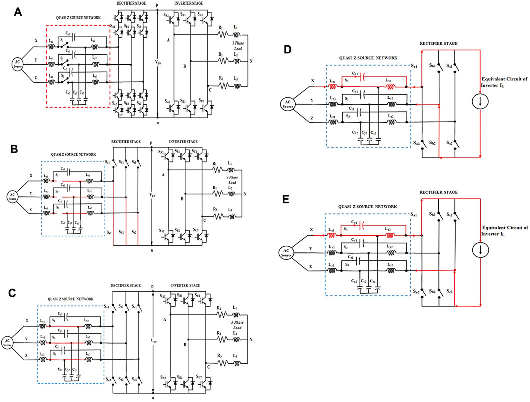
FIGURE 1. Equivalent circuit of the QZS indirect matrix converter: (A) circuit diagram, (B) shoot-through state, (C) non-shoot-through state, (D) when Sb2 is turned ON, and (E) Sc2 is turned ON.
2.1 Operating modes
The proposed continuous QZS network comprises three inductor pairs (Lx1 and Lx2, Ly1 and Ly2, and Lz1, Lz2), six capacitors (Cx1, Cx2, Cy1, Cy2, Cz1, and Cz2), and three switches (S1, S2, and S3). As the three switches have the same switching behavior, a single pulse S0 can be used to control switches S1, S2, and S3. Figures 1B, C indicate the equivalent circuit of the QZSIMC for the shoot-through and active states.
2.2 Shoot-through state
During the shoot-through state, the power switches S1, S2, and S3 of the QZS network are turned off (S0 = 0), as shown in Figure 1B. At the same time, the switches at the bottom of the rectifier are turned ON, initiating the charging of QZS inductors in each phase. For a total time period of Ts, the shoot-through state’s time interval is given by DTs.
During this state, the voltage equations across the inductors Lx1, Ly1, and Lz1 are given by Eqs 1–3, and the voltage across the capacitors Cx2, Cy2, and Cz2 is equal to the voltage across the inductors Lx2, Ly2, and Lz2, as shown in Eq. 4.
The current equations of inductor pairs during the shoot-through state are given by Eqs 5, 6:
2.3 Active state
For the duration of the active state, all three switches are twisted ON (S0 = 1), as shown in the equivalent circuit of Figure 1C. The output voltage at the QZS network, across each phase, is the summation of two capacitor voltages due to the discharge of the inductor to the capacitors. However, the time period of the active state is given by (1-D) Ts.
Furthermore, during the non-shoot-through state (Liu et al., 2015), the voltage across the capacitors Cx1, Cy1, and Cz1 can be given by Eq. 7, and the voltage across the inductors Lx1, Ly1, and Lz1 can be derived, as shown in Eqs 8–10.
Hence, by substituting the values of VCX1, VCy1, and VCZ1 in Eqs 8–10, Eqs 11–13 can be obtained.
The current equations during the active state are given by Eqs 14–16.
For a total time period of Ts, the shoot-through time period is T0, the active time period is T1, and the duty ratio at the time of shoot-through is given as D = T0/Ts. Under a steady state, over one total time period, the average voltages of the inductor and average currents of the capacitor should be 0. From Eqs 1–16, the following Eqs 17–20 have been derived:
Combining Eqs 11–20, we obtain
where
If Vs is stated as the amplitude of input voltages (VX, VY, and VZ) and Vo is denoted as the amplitude of the voltages at the output (V'X, V'Y, and V'Z) (Siwakoti et al., 2015), then the boost factor is given in Eq. 21:
The gain G of the QZSIMC is given by Eq. 22:
where
M = mim0 is the modulation index of the QZSIMC.
In the design of QZS, parameters such as QZS inductors have to be chosen such that it should limit the high frequency current ripple and the QZS capacitors must limit the voltage ripples in the circuit, and hence, the QZS network must satisfy the aforementioned functions of the filter.
3 Modified space vector modulation
The QZSIMC is made up of a rectifier and inverter. The rectifier can be adjusted by the input current-fed MSVPWM to accomplish a convenient power factor. Meanwhile, to adjust the output voltage, the voltage-fed MSVPWM is utilized in the back-end converter.
3.1 The rectification stage input current MSVPWM
The rectification stages of the new QZSIMC have an active vector, shoot-through vector, and zero vector. The modified space vector diagram of the rectification stage is separated into six separate sectors.
We assume that the rectifier operates in sector 1 and that the voltage at the input VX is positive with the highest value. This results in the superior switch Sa1 of leg X being turned ON, and the switches Sb2 and Sc2 in the next phase are modulated. The zero current vector I0 and the two non-shoot-through vectors (I1 and I6) are used to create the input current reference vector Iref in a specific sector. Figures 1D, E show the circuit of the rectifier when Sb2 is in the ON state and Sc2 is in the ON state, respectively.
The modified space vector diagram of the rectification stage is shown in Figure 2A. To boost the voltage, the ac sources are short-circuited when the shoot-through state is added to the zero states of the rectifier, as shown in Supplementary Table S2.
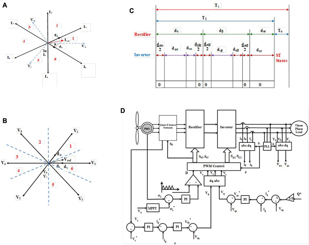
FIGURE 2. Modified space vector diagram for the (A) front-end rectifier and (B) back-end inverter. (C) Switching sequence of the QZSIMC and (D) closed-loop controller for the QZSIMC.
The constant shoot-through vector is included in the zero vector, and the vector duty cycle can be given by Eq. 23.
where
mi—rectifier modulation;
3.2 The inversion stage output voltage MSVPWM
The two switches in the output phases are operated complementarily to one another to prevent switching states that could lead to short-circuit of the dc link. The inverter comprises six active and two zero vectors. Figure 2B shows the modified space vector representation of the voltage inversion stage, which has six sectors in the complex plane. The vector duty cycle can be calculated as shown in Eq. 24.
where
mo—modulation index corresponding to the inversion stage;
Supplementary Table S4 provides the switching sequence of the inverter stage. By using two contiguous switching voltage vectors (V1 and V2) and a zero vector V0, the modified space vector of the required output can be synthesized.
3.3 Rectification and inversion stage switch combination synchronization
The control technique should combine all possible combinations of switching states for rectifiers and inverters to balance currents at the input and voltages at the output within a switching time period. T0 is the time period of the shoot-through state. In contrast, the time period of the active state T1 combines the switching time period of both the rectification and inversion stages. The duty cycle of the input current vector Iref in vectors I1, I6, and Io is dα and dβ, which are then shared in proportion between the duty cycle of output voltage vectors V1, V2, and V0, labeled as dµ and dυ. This complete switching sequence is given in Figure 2C, and its duty cycle can be given by Eq. 25.
where Ts is the total switching period, and
4 Controller for the QZSIMC-based WECS
The main function of the QZSIMC is to retain the fixed voltage and frequency, regardless of the wind fluctuations at the input side and variations in load conditions. The high-performance QZSIMC should have distortion-free and constant output voltage fed to the load. Thus, the closed-loop controller for the QZSIMC (Amei et al., 2002) has been emphasized in this section to keep up constant output parameters and also to generate the reference sinusoidal signals (Rodriguez et al., 2012). Figure 2D shows the diagrammatic representation of the proposed PWM control scheme for the QZSIMC, which includes two parts: the main circuit and the modulation algorithm.
In the MPPT approach of the closed-loop controller, from the obtained wind velocity, the reference rotor speed ωr* at which utmost power can be extracted has been estimated. The error signal acquired by subtracting the real rotor speed ωr measured from the PMG and reference rotor speed ωr* at each wind speed Vω is fed to a PI controller. Hence, the maximum power is attained when the rotor speed tracks its reference value ωr*.
The closed-loop controller consists of two loops to control active and reactive powers. The closed-loop controller is mainly built on Park/Clarke transformation, which transforms the electrical quantities into a dqo reference frame. In this closed-loop controller, the three-phase load voltages and currents are converted to dq axis components such as Vds, Vqs, id, and iq using Park/Clarke transformation. The error signal generated by comparing the actual capacitor voltage with the reference capacitor voltage is managed through the PI controller to produce the reference d-axis current id*. Similarly, the current reference component of q-axis iq* is estimated from the measured reactive power and d-axis voltage Vds.
Furthermore, error signals obtained by comparing the actual dq-axis current and reference dq-axis current are processed through the controllers to produce the dq-axis reference voltages, which are then compared with the actual dq-axis voltages (Vds and Vqs) to generate the two-phase dq axis voltages (Vd and Vq). Furthermore, the two-phase voltages are converted into the three-phase reference voltages (Vx, Vy, and Vz) using inverse Park/Clarke transformation. The obtained sinusoidal reference signal is set as input to the PWM controller, which, in turn, generates PWM pulses for the QZSIMC.
5 Results and discussion
The simulation of the QZSIMC topology suggested in the previous section has been performed in a MATLAB/SIMULINK platform along with the modeled wind turbine and radial flux permanent magnet generator (RFPMG) (Alizadeh and Shokri Kojuri, 2017). To obtain stable voltage and current in the output from a variable voltage source of PMG, a suitable controller has been designed. Figure 3A shows the simulated PMG-generated output voltage for a wind speed of 7 m/s with the turbine speed and output voltage of approximately 130 rpm and 173 V, respectively.
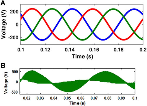
FIGURE 3. Simulated output voltage of (A) PMG; (B) QZS network for CBPWM-based QZSIMC.
5.1 Performance analysis of the QZSIMC-based WECS
The performance analysis of the QZSIMC with two PWM schemes has been carried out based on the parameters like switching voltage stress, current stress, shoot-through duty ratio, voltage gain, and THD for various wind velocity and load conditions. The two PWM schemes considered are CBPWM and MSVPWM schemes, and the results are analyzed under two cases to predict the better PWM scheme for the QZSIMC.
5.1.1 Case 1: QZSIMC with carrier-based pulse-width modulation
Figure 3B presents the voltage waveform of the QZS network for CBPWM-based QZSIMC with a value of 548 V. Figure 4A–C shows the current of an inductor, the voltage of the capacitor, and the intermediate dc link voltage of QZSIMC with a carrier-based PWM technique for a wind velocity of 7 m/s.
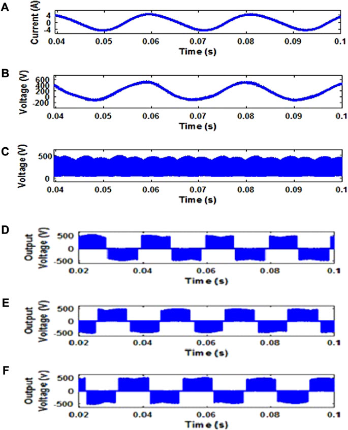
FIGURE 4. Simulated outputs of CBPWM-based QZSIMC for (A) inductor current, (B) capacitor voltage, (C) DC link voltages, and (D) Vab, (E) Vbc, and (F) Vca line voltages without a filter.
The output line voltage of the QZSIMC with the PMG-based WECS under the CBPWM scheme is shown in Figure 4D–F separately for three phases without a filter. Figure 5 demonstrates the constant three-phase voltages of the QZSIMC without a filter and with a filter, respectively. Figure 6A, B denotes the constant output 230-V phase voltage of the QZSIMC corresponding to three phases separately without a filter and with a filter. The constant output voltage is obtained for a D value of 0.3 and an M value of 0.7.
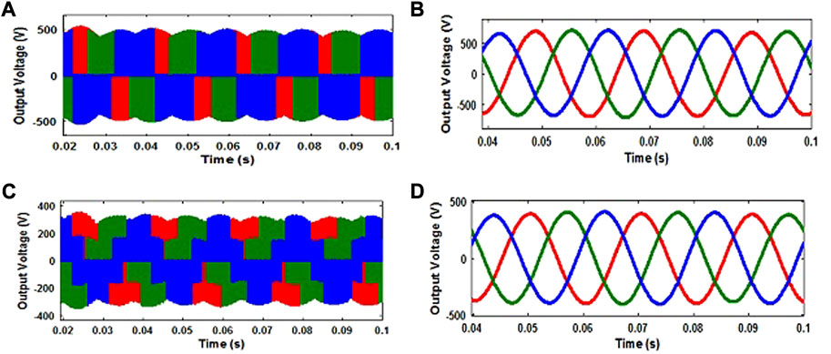
FIGURE 5. Simulated outputs of CBPWM-based QZSIMC for (A) line voltage without a filter, (B) line voltage with a filter, (C) phase voltage without a filter, and (D) phase voltage with a filter.
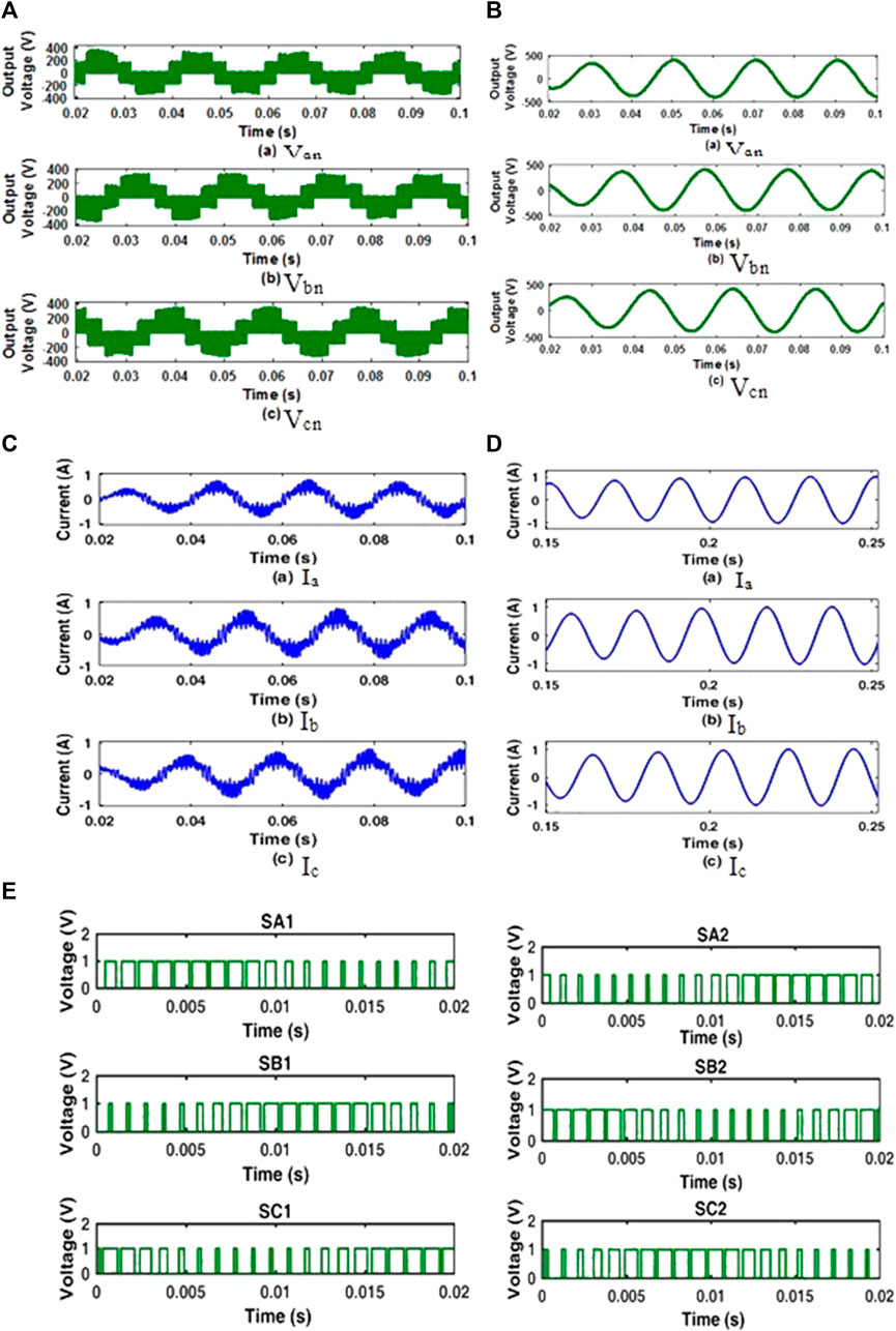
FIGURE 6. Simulation results of CBPWM based QZSIMC (i) Phase Voltages without filter (ii) Phase voltages with filter (iii) Output Currents without filter (iv) Output Currents with filter (v) Switching Pattern.
The output currents of CBPWM-based QZSIMC without a filter and with a filter at a load of 0.25 kW are shown in Figure 6C, D respectively. In addition, the switching pattern for the inverter part of the QZSIMC under the CBPWM scheme is shown in Figure 6E.
5.1.2 Case 2: QZSIMC with modified space vector pulse-width modulation
The QZSIMC performance under the MSVPWM scheme is investigated for a wind velocity of 7 m/s. The inductor current, voltage across the capacitor, and inter-link voltage waveforms under the MSVPWM scheme are presented in Figure 7A–C. When compared to CBPWM, the magnitude of the current and voltage ripples of the QZS network under the MSVPWM scheme are very much reduced, and thus, the switching loss is also reduced.
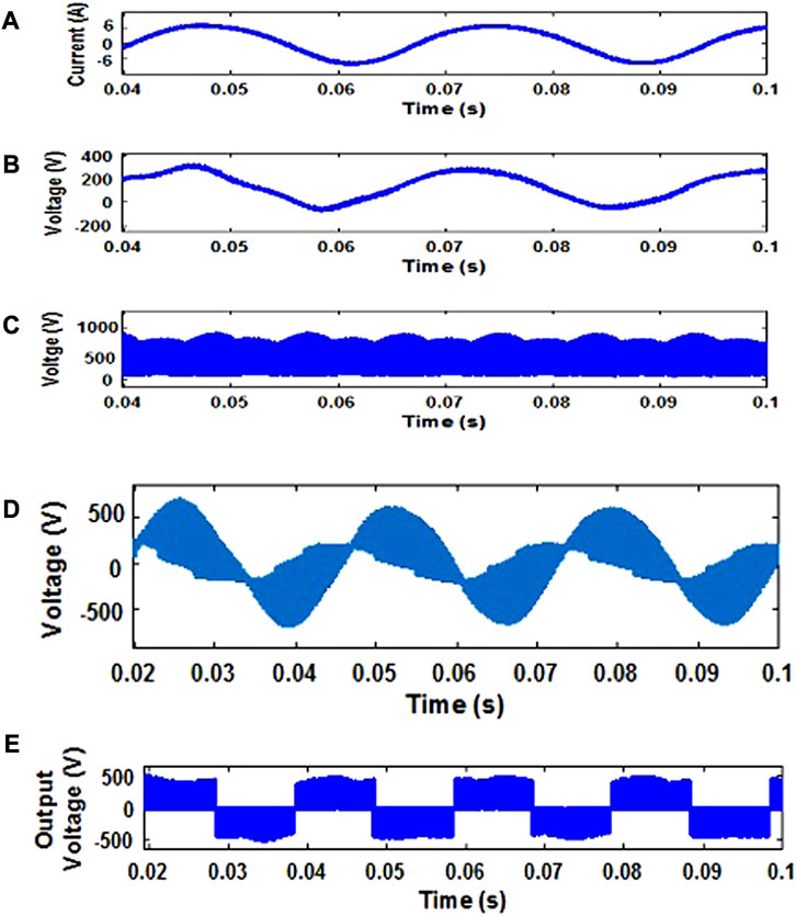
FIGURE 7. Simulated outputs of MSVPWM-based QZSIMC for (A) inductor current, (B) capacitor voltage, (C) DC link voltage, (D) output voltage of the QZS network, and (E) line voltage without a filter.
Figure 7D illustrates the output voltage waveform of the QZS network for the MSVPWM-based QZSIMC with a value of 777 V. The output line voltage of the QZSIMC with PMG-based WECS under the MSVPWM scheme is shown in Figure 7E separately for a single phase without a filter. Figure 8 shows the three-phase voltage waveforms of QZSIMC without a filter and with a filter. Figure 9A, B denotes the constant output 230-V phase voltage of QZSIMC corresponding to three phases separately without a filter and with a filter, respectively, under the MSVPWM scheme.
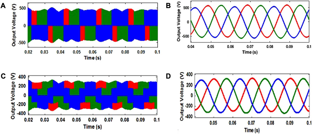
FIGURE 8. Simulated outputs of MSVPWM-based QZSIMC for the (A) line voltage without a filter, (B) line voltage with a filter, (C) phase voltage without a filter, and (D) phase voltage with a filter.
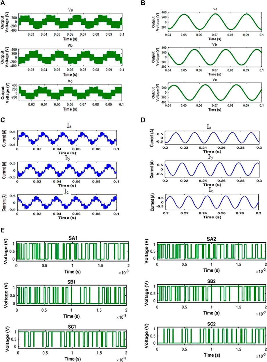
FIGURE 9. (A) Simulation on results of MSVPWM based QZSIMC for phase voltages without filter. (B) Simulation results of MSVPWM based QZSIMC for phase voltages with filter. (C) Simulation on results of MSVPWM based QZSIMC for output currents without filter. (D) Simulation results of MSVPWM based QZSIMC for output currents with filter. (E) Switching pattern of MSVPWM based QZSIMC.
The individual output currents of MSVPWM-based QZSIMC without a filter and with a filter for all three phases at an RL load of 0.25 kW are shown in Figure 9C, D respectively. To obtain the required value of current and voltage at the output, the pulses generated for a D value of 0.23 and an M value of 0.74 with a switching frequency of 10 kHz are shown in Figure 9E.
5.2 Performance analysis of QZSIMC under different loading conditions
The fast Fourier transform spectra of output parameters are analyzed under one-fourth load conditions. Figure 10A–C shows the simulated THD of the output voltage and current of the QZSIMC with a filter under both CBPWM and MSVPWM schemes with an RL load of 0.25 kW. The figure perceived that the output line voltage THD values of CBPWM and MSVPWM schemes are 2.44% and 1.8%, respectively, and the fundamental line voltage is different for both PWM techniques. Since the reference waveforms and the modulation index are different for the two PWM techniques, it may be realized that the notch instances may not occur at regular time intervals.
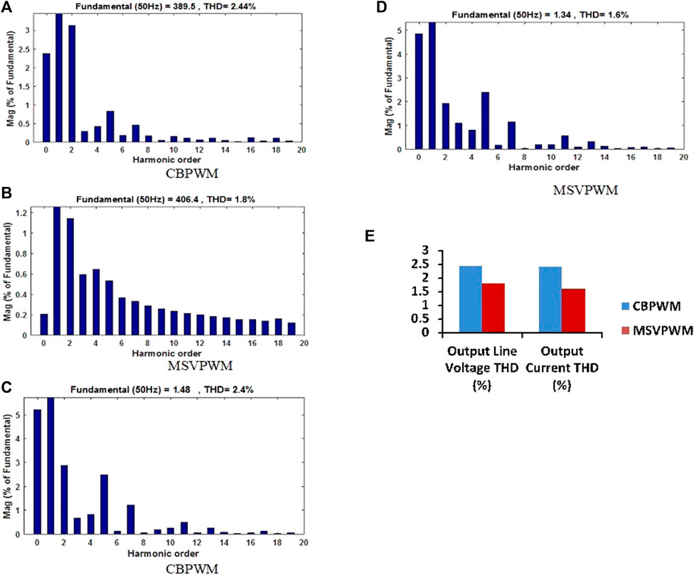
FIGURE 10. (A,B) Simulated output line voltage THD of QZSIMC, (C,D) Simulated output current THB of QZSIMC (E) Comparsion of output line voltage and current THB for QZSIMC.
However, the output current THD of CBPWM and MSVPWM schemes are 2.4% and 1.6%, correspondingly, as shown in Supplementary Table S4. The output voltage and current THD of the QZSIMC for CBPWM and MSVPWM schemes are given in Figure 10E. From Figure 10E, it is suggested that the voltage THD of the MSVPWM scheme based on the QZSIMC is almost 0.64% lesser than that of the CBPWM scheme.
However, the output current THD of the MSVPWM scheme-based QZSIMC with a filter is almost 0.8% lesser than that of the CBPWM scheme. As the THD of MSVPWM-based QZSIMC is less, the conduction loss in the switches will also be less, which, in turn, results in an increased efficiency.
5.3 Analysis of switching stress
Figure 11A shows the switching current stress of MSVPWM-based QZSIMC is 3 A lower than that of CBPWM-based QZSIMC at all operating points. Figure 11B shows the variation in switching voltage stress in the power switches of the QZSIMC with the variation in the shoot-through duty ratio under both CBPWM and MSVPWM schemes. The voltage stress in the MSVPWM scheme is approximately 150 V lower than that of the CBPWM scheme.
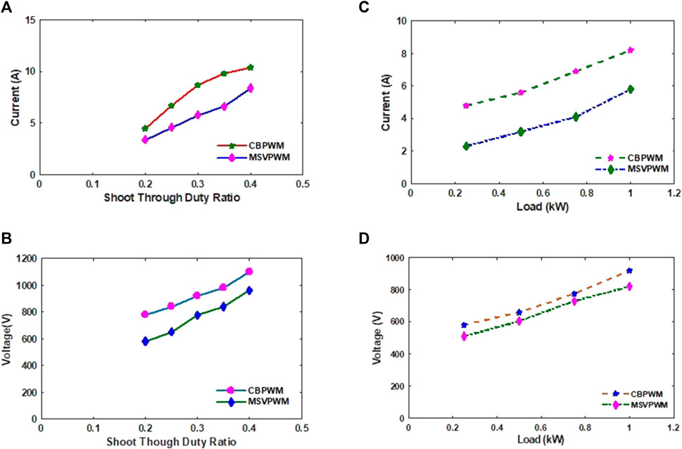
FIGURE 11. (A) Current stress versus shoot through duty ratio of QZSIMC. (B) Voltage stress versus Shoot through duty ratio of QZSIMC. (C) Current stress of QZSIMC at different loading conditions. (D) Voltage stress of QZSIMC at different loading conditions.
Figure 11C, D shows the variation in current stress and voltage stress across power switches of the QZSIMC under both CBPWM and MSVPWM schemes correspondingly for different load conditions. For a load of 1 kW, the current stress and voltage stress of the MSVPWM scheme are approximately 2.5 A and 80 V lesser than those of the CBPWM-based QZSIMC.
5.4 Experimental setup
An experimental prototype of the three-phase rectifier, inverter, and QZS network has been set up to validate the experimental and simulation results, as shown in Figure 12A. The prototype model of the QZSIMC has been developed, and the experiments are conducted to obtain the output voltages for different loading conditions. Figure 12B depicts the block diagram of the experimental setup of the proposed QZSIMC. The experimental prototype consists of four parts: the FPGA processor, power circuit, gate driver circuit, and measurement circuits. The FPGA Spartan-6 processor is used to control the proposed matrix converters. The analog signals are measured with the help of voltage and current sensors. The measured analog signals are processed through signal conditioners and fed as input to the add-on card of the FPGA processor. The add-on card is utilized to convert the input analog signal into the digital signal, which is then fed as input to the FPGA for further processing.
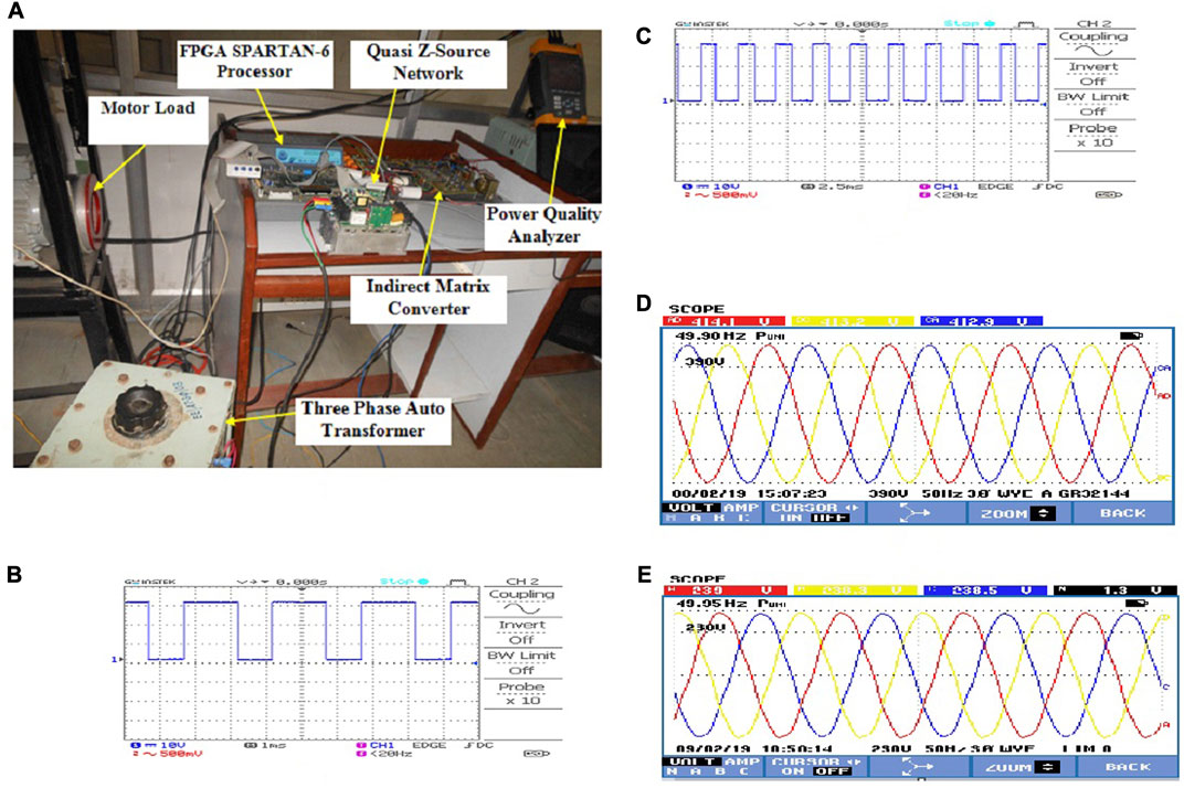
FIGURE 12. Experimental outputs of QZSIMC (A), prototype (B), and (C) PWM pulses for QZSIMC, (D) output line voltage, and (E) phase voltage.
The voltage transducers are employed to measure the output voltage. The measured output AC signal is given as input to the A/D converter through a signal conditioning circuit. Likewise, the current transducers are utilized to measure the output currents. The function of the signal conditioning circuit is to modify the measured ac output signal from the current transducer and fed as input to the A/D converter. The digital outputs obtained from the A/D converter are linked to the I/O ports of the FPGA interface board.
To attain the preferred output voltage, the time period of the QZS network is properly adjusted according to the input variations. The Spartan-6 FPGA processor is utilized to produce the PWM pulses along with the shoot-through period. From the simulation results, it could be inferred that the MSVPWM scheme is more suitable for the QZSIMC than the CBPWM scheme. Hence, the PWM pulses for the proposed QZSIMC are generated by implementing the MSVPWM strategy. The PWM pulses for the IGBT switches in the first leg of the rectifier with a duty ratio of 0.23 and modulation index of 0.74 are shown in Figure 12C, D.
For a wind velocity of 7 m/s, the experimental output line voltage obtained for the QZSIMC is 414.1 V, 50 Hz with an input voltage of approximately 173 V, which is represented in Figure 12E. Due to the intermittent nature of wind, the output of the PMG and proposed QZSIMC will be varying. By adjusting the duty ratio and modulation index, the desired constant output line voltage has been obtained for a standalone load. Figure 12F illustrates the output phase voltage of the proposed QZSIMC under the MSVPWM scheme. The output phase voltage obtained experimentally is approximately 239 V. For a load of 0.25 kW, the output load current with a filter is 0.5 A, as shown in Figure 13A–C, which represents the experimental output line voltage THD of 4.2% and an output current THD of 4% for the QZSIMC with the MSVPWM scheme, respectively. As the output line voltage THD and current THD with the MSVPWM scheme are very less, the loss in the converter will be reduced, which, in turn, increases the efficiency.
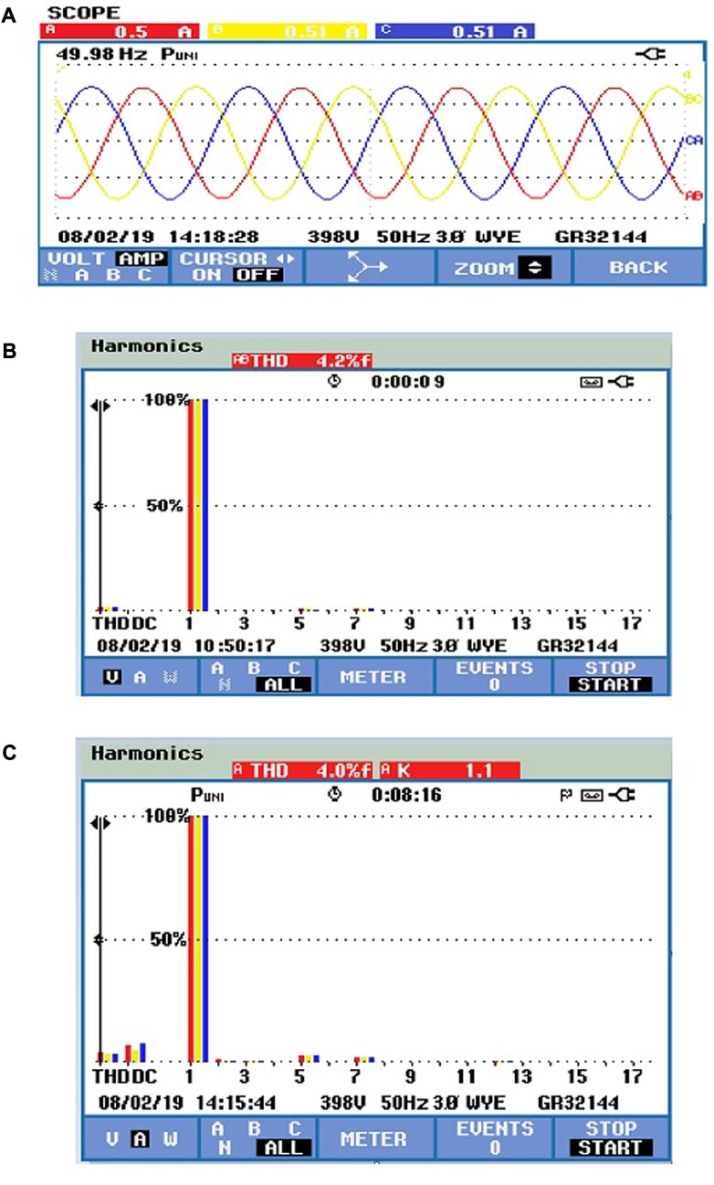
FIGURE 13. Experimental output for QZSIMC (A) load current, (B) line voltage THD, and (C) output current THD.
6 Conclusion
To overcome the drawbacks of conventional power converters, in this paper, a QZSIMC has been proposed. The novel QZSIMC topology provides advantages such as a simpler structure, easy operation, and filtering function that avoids the need for an extra LC filter. The carrier-based PWM technique has been suggested to control the proposed QZSIMC, and it has been found that even though the shoot-through insertion is simple, it is complex to implement and provides high switching loss and poor power quality. Hence, a modified space vector modulation scheme with easy control overshoot was proposed in this paper, which effectively enhance the voltage transfer ratio and reduces the voltage stress at the capacitor of the QZS network. To predict suitable PWM techniques and also to verify the simulation results, an experimental prototype set up for the QZSIMC has been fabricated and tested. Two different switching schemes have been implemented and compared based on the parameters like switching stress, shoot-through period, boost factor, and THD. From the result analysis, it could be observed that the switching stress of the MSVPWM scheme is lesser than that of the CBPWM scheme, and moreover, the shoot-through variation according to the input voltage variation is faster in MSVPWM than that in CBPWM. For a load of 0.25 kW, the experimental output line voltage harmonic spectra and output current harmonic spectra of MSVPWM are 4.2% and 4%, respectively. It has been concluded that among the two switching schemes, the MSVPWM scheme is a better choice for the QZSIMC. Wind’s unpredictable nature creates voltage instability, frequency oscillation, and minor signal stability concerns in wind power systems. As a result, the transient stability of PMG-based WT must be investigated. The limitations in voltage amplification, the complexity of the control circuit, and the vast amount of energy electronic devices are some of the key restrictions in implementing the QZSIMC for the WECS. The future perspective is to investigate the performance of the proposed converter under the over-modulation region of SVPWM and to develop a flexible and efficient intelligent control algorithm for maximum power point tracking (MPPT) with independent wind turbine characteristics. The intelligent algorithm can capture maximum power under varying wind velocities and air density by utilizing its estimate mechanism and adaptive memory. As the algorithm is trained, it continuously adjusts to its given turbine by developing system characteristics throughout the system operation.
Data availability statement
The original contributions presented in the study are included in the article/Supplementary Material; further inquiries can be directed to the corresponding author.
Author contributions
Conceptualization, KM and CK; methodology, KM and CK; software, KM and CK; validation, KM and CK; formal analysis, KM and CK; investigation, KM and CK; resources, KM and CK; data curation, KM and CK; writing—original draft preparation, KM and CK; writing—review and editing, KM and CK; visualization, PB and TS; supervision, PB and TS; project administration, PB and TS. All authors contributed to the article and approved the submitted version.
Conflict of interest
The authors declare that the research was conducted in the absence of any commercial or financial relationships that could be construed as a potential conflict of interest.
Publisher’s note
All claims expressed in this article are solely those of the authors and do not necessarily represent those of their affiliated organizations, or those of the publisher, the editors, and the reviewers. Any product that may be evaluated in this article, or claim that may be made by its manufacturer, is not guaranteed or endorsed by the publisher.
Supplementary material
The Supplementary Material for this article can be found online at: https://www.frontiersin.org/articles/10.3389/fenrg.2023.1230641/full#supplementary-material
Abbreviations
B, voltage boost factor; Cx1, Cx2, Cy1, Cy2, Cz1, and Cz2, quasi Z-source network capacitances; CMC, conventional matrix converter; CBPWM, carrier-based pulse-width modulation; D, shoot-through duty ratio; DMC, direct matrix converter; DDWECS, direct-drive wind energy conversion systems; G, voltage gain; IMC, indirect matrix converter; IGBT, insulated gate bipolar transistor; io, output current (A); Lx1, Lx2, Ly1, Ly2, Lz1, and Lz2, quasi Z-source network inductances; MC, matrix converter; MSVPWM, modified space vector pulse-width modulation; PMG, permanent magnet generator; QZSIMC, quasi Z-source indirect matrix converter; QZS, quasi Z-source; RFPMG, radial flux permanent magnet generator; S1, S2, and S3, quasi Z-source network power switches; T0, shoot-through state; T1, non-shoot-through state; Ts, switching cycle; THD, total harmonic distortion; Vo, output voltage (V); Vs, input voltage; VSI, voltage source inverter; VX, VY, and VZ, input voltages; V’X, V’Y, and V’Z, output reference voltages; WECS, wind energy conversion system; ZSMC, Z-source matrix converter.
References
Alizadeh, M., and Shokri Kojuri, S. (2017). Modelling, control, and stability analysis of quasi-Z-source matrix converter as the grid interface of a PMSG-WECS. Transm. Distribution 11 (14), 3576–3585. doi:10.1049/iet-gtd.2017.0178
Amei, K., Takayasu, Y., Ohji, T., and Sakui, M. (2002). A maximum power control of wind generator system using a permanent magnet synchronous generator and a boost chopper circuit. Proc. PCC, Osaka, Jpn. 3, 1447–1452.
Anderson, J., and Peng, F. Z. (2008). “A Class of quasi-Z-source inverters,” in Proc. Of IEEE industry applications society annual meeting, 1–7.
Bharanikumar, R., Kumar, A. N., and Maheswari, K. T. (2010b). Novel MPPT controller for wind turbine driven permanent magnet generator with power converters. Int. Rev. Electr. Eng. 5 (4).
Bharanikumar, R., Nirmalkumar, A., and Maheswari, K. T. (2010a). Modelling and simulation of wind turbine driven axial type permanent magnet generator with Z-source inverter. Aust. J. Electr. Electron. Eng. 9 (1), 27–42. doi:10.7158/e10-849.2012.9.1
Chalmers, B. J., Wu, W., and Spooner, E. (1999). An axial-flux permanent-magnet generator for a gearless wind energy system. IEEE trans. Energy Convers. 14 (2), 251–257. doi:10.1109/60.766991
Chan, T. F., and Lai, L. L. (2007). An axial-flux permanent-magnet synchronous generator for A direct-coupled wind-turbine system. IEEE Trans. Energy Convers. 22 (1), 86–94. doi:10.1109/tec.2006.889546
Cho, J. G., and Cho, G. H. (2013). Soft-switched matrix converter for high-frequency direct AC-to-AC power conversion. Int. J. Electron. 72 (4), 669–680. doi:10.1080/00207219208925607
Deng, Weitao (2020). Maximum voltage transfer ratio of matrix converter under DTC with rotating vectors. IEEE Trans. Energy Convers. 36 (6), 6137–6141. doi:10.1109/tpel.2020.3033414
Dubois, M. R., Polinder, H., and Ferreira, J. A. (1992). Comparison of generator topologies for direct-drive wind turbines. Manchester UK: ICEM 92, 761–765.
Guo, M., Liu, Y., Ge, B., Xiao, L., Aníbalde Almeida, T., and Fernando, J. T. E. (2023). Dual, three-level, quasi-Z-source, indirect matrix converter for motors with open-ended windings. IEEE Trans. Energy Convers. 38 (1), 64–74. doi:10.1109/tec.2022.3187419
Hakemi, A., and Monfared, M. (2017). Very high gain three-phase indirect matrix converter with two Z-source networks in its structure. IET Renew. Power Gener. 11 (5), 633–641. doi:10.1049/iet-rpg.2016.0368
Hojabri, H., Mokhtari, H., and Chang, L. (2013). Reactive power control of permanent magnet synchronous wind generator with matrix converter. IEEE Trans. Power Deliv. 28 (2), 575–584. doi:10.1109/TPWRD.2012.2229721
Jussila, M., and Tuusa, H. (2006). “Comparison of direct and indirect matrix converters in induction motor drive,” in Proc. 32nd Annu. Conf. IEEE Ind. Electron, Paris, France, 6-10 Nov. 2006 (IEEE), 1621–1626. doi:10.1109/IECON.2006.347423
Kim, S., Sul, S., and Lipo, T. A. (2000). AC/AC power conversion based on matrix converter topology with unidirectional switches. IEEE Trans. Ind. Appl. 36 (1), 139–145. doi:10.1109/28.821808
Kumar Ramasamy, B., and Maheswari, K. T. (2017). Single stage power conversion for wind energy system using Ac-ac matrix converter. J. Electr. Eng. 17 (4), 1–7.
Lei, Q., Peng, F. Z., and Ge, B. (2012). Pulse-width-amplitude modulated voltage-fed quasi-Z-source direct matrix converter with maximum constant boost. 27th Annu. IEEE Appl. Power Electron. Conf. Expo. 6, 641–646. doi:10.1109/APEC.2012.6165886
Li, H., and Chen, Z. (2007). “Design optimization and comparison of large direct-drive permanent magnet wind generator systems,” in Proc International Conference on Electrical Machines and Systems, Seoul, Korea (South), 8-11 Oct. 2007 (IEEE), 685–690. doi:10.1109/ICEMS12746.2007.4412171
Li, J., Keqing, Q., Song, X., and Chen Guo, C. (2009). “Study on control methods of direct drive wind generation system based on three-phase Z-source inverter,” in Ieee int. Conf. Power electronics motion control, IPEMC, 644–649.
Liao, K., Lu, D., Wang, M., and Yang, J. (2022). A low-pass virtual filter for output power smoothing of wind energy conversion systems. IEEE Trans. Industrial Electron. 69 (12), 12874–12885. doi:10.1109/tie.2021.3139177
Liu, S., Ge, B., Jiang, X., Abu-Rub, H., and Peng, F. Z. (2015). Simplified quasi-Z source indirect matrix converter: SIMPLIFIED QZS INDIRECT MATRIX CONVERTER fied quasi-Z source matrix converter. Intern. J. Circuit Theory Appl. 43. 1775–1793. doi:10.1002/cta.2032
Liu, S., Ge, B., Liu, Y., Abu-Rub, H., Balog, R. S., and Sun, H. (2016). Modeling, analysis, and parameters design of LC-filter-integrated quasi-Z-source indirect matrix converter. IEEE Trans. Power Electron. 31 (11), 7544–7555. doi:10.1109/tpel.2016.2553582
Liu, X., Loh, P. C., Wang, P., and Han, X. (2012). Improved modulation schemes for indirect Z-source matrix converter with sinusoidal input and output waveforms. IEEE Trans. Power Electron. 27 (9), 4039–4050. doi:10.1109/tpel.2012.2188415
Maheswari, K. T., Bharanikumar, H., and Bhuvaneswari, S. (2019). “A review on matrix converter topologies for adjustable speed drives,” in International journal of innovative Technology and exploring engineering (IJITEE), 8, 53–57.
Nguyen, T. D., and Lee, H. H. (2014). A new SVM method for an indirect matrix converter with common-mode voltage reduction. IEEE Trans. Ind. Inf. 10 (1), 61–72. doi:10.1109/tii.2013.2255032
Park, K., Jou, S. T., and Lee, K.-B. (2009). “Z-source matrix converter with unity voltage transfer ratio,” in Proc. 35th IEEE IECON (Porto, Portugal: IEEE), 4523–4528.
Ramalho, A. W. S., Vitorino, M. A., Corrêa, M. B. d. R., Costa, L. A. L. d. A. C., and Braga-Filho, E. R. (2022). New family of two-to-three-phase AC–AC indirect matrix converters with open-end rectifier stage. IEEE Trans. Industry Appl. 58 (1), 517–530. doi:10.1109/tia.2021.3128369
Rodriguez, J., Rivera, M., Kolar, J. W., and Wheeler, P. W. (2012). A review of control and modulation methods for matrix converters. IEEE Trans. Ind. Electron. 59 (1), 58–70. doi:10.1109/TIE.2011.2165310
Shigeuchi, K., Xu, J., Shimosato, N., and Sato, Y. (2021). A modulation method to realize sinusoidal line current for bidirectional isolated three-phase AC/DC dual-active-bridge converter based on matrix converter. IEEE Trans. Power Electron. 36 (5), 6015–6029. doi:10.1109/tpel.2020.3026977
Shuo, L., Baoming, G., Abu-Rub, H., Xinjian, J., and Peng, F. Z. (2014). Modeling, analysis, and motor drive application of quasi-Z source indirect matrix converter. Int. J. Comput. Math. Electr. Electron. Eng. 33 (12), 298–319.
Shuo, L., Baoming, G., Abu-Rub, H., Xinjian, J., and Peng, F. Z. (2013). “A novel indirect quasi-Z-source matrix converter applied to induction motor drives,” in Proc. IEEE energy convers. Congr. Expo, 2440–2444.
Siwakoti, Y. P., Peng, F. Z., Blaabjerg, F., Loh, P. C., and Town, G. E. (2015). Impedance-source networks for electric power conversion part I: A topological review. IEEE Trans. Power Electron. 30 (2), 699–716. doi:10.1109/tpel.2014.2313746
Thangavel, M. K., Ramasamy, B. K., and Ponnusamy, P. (2020). Performance analysis of dual space vector modulation technique-based quasi Z-source direct matrix converter. Electr. Power Components Syst. Vo. 48 (11), 1185–1196. doi:10.1080/15325008.2020.1834018
Trentin, A., Empringham, L., de Lillo, L., Zanchetta, P., Wheeler, P., and Clare, J. (2016). Experimental efficiency comparison between a direct matrix converter and an indirect matrix converter using both Si IGBTs and SiC <sc>mosfet</sc>s. IEEE Trans. Ind. Appl. 52 (5), 4135–4145. doi:10.1109/tia.2016.2573752
Vidhya, S., and Venkatesan, T. (2018). Quasi-Z-source indirect matrix converter fed induction motor drive for flow control of dye in paper mill. IEEE Trans. Power Electron. 33 (2), 1476–1486. doi:10.1109/tpel.2017.2675903
Waghmare, M. A., Umre, B. S., Aware, M. V., Iqbal, A., and Kumar, A. (2023). Dual stage single-phase to multiphase matrix converter for variable frequency applications. IEEE Trans. Energy Convers. 38 (2), 1372–1377. doi:10.1109/tpel.2022.3207515
Wheeler, P. W., Rodriguez, J., Clare, J. C., Empringham, L., and Weinstein, A. (2002). Matrix converters; a technology review. IEEE Trans. Ind. Electron. 49 (2), 276–288. doi:10.1109/41.993260
Xu, Y., Wang, Z., Liu, P., Qiang, W., Deng, F., and Zou, Z. (2020). The modular current-fed high-frequency isolated matrix converters for wind energy conversion. IEEE Trans. Energy Convers. 37 (4), 4779–4791. doi:10.1109/tpel.2021.3123204
Xu, Y., Wang, Z., Zou, Z., Buticchi, G., and Liserre, M. (2022). Voltage-fed isolated matrix-type AC/DC converter for wind energy conversion system. IEEE Trans. Industrial Electron. 69 (12), 13056–13068. doi:10.1109/TIE.2022.3140524
Yaramasu, V., and Wu, B. (2014). Predictive control of a three-level boost converter and an NPC inverter for high-power PMSG-based medium voltage wind energy conversion systems. IEEE Trans. Power Electron. 29 (10), 5308–5322. doi:10.1109/TPEL.2013.2292068
You, X., Ge, B., Liu, S., Nie, N., Jiang, X., and Abu-Rub, H. (2016). Common mode voltage reduction of quasi-Z source indirect matrix converter. Int. J. Circuit Theory Appl. 44 (1), 162–184. doi:10.1002/cta.2069
Zahra, M., Mohammad, J., Dan, X., and Jianguo, Z. (2015). “Analysis of direct matrix converter operation under various switching patterns,” in IEEE Conference on Power Electronics and Drives Systems (PEDS), Sydney, Australia, 9-12 June 2015 (IEEE), 630–634. doi:10.1109/PEDS.2015.7203549
Keywords: quasi Z source indirect matrix converter (QZSIMC), modified space vector pulse width modulation (MSVPWM), small signal model, total harmonic distortion (THD), voltage gain
Citation: Maheswari KT, Kumar C, Balachandran PK and Senjyu T (2023) Modeling and analysis of the LC filter-integrated quasi Z-source indirect matrix converter for the wind energy conversion system. Front. Energy Res. 11:1230641. doi: 10.3389/fenrg.2023.1230641
Received: 29 May 2023; Accepted: 08 August 2023;
Published: 25 August 2023.
Edited by:
Joshuva Arockia Dhanraj, Hindustan University, IndiaReviewed by:
Anitha Gopalan, Saveetha University, IndiaMohamed Salem, University of Science Malaysia (USM), Malaysia
Mohit Bajaj, Graphic Era University, India
Copyright © 2023 Maheswari, Kumar, Balachandran and Senjyu. This is an open-access article distributed under the terms of the Creative Commons Attribution License (CC BY). The use, distribution or reproduction in other forums is permitted, provided the original author(s) and the copyright owner(s) are credited and that the original publication in this journal is cited, in accordance with accepted academic practice. No use, distribution or reproduction is permitted which does not comply with these terms.
*Correspondence: K. T. Maheswari, bWFoZXN3YXJpa3RAZ21haWwuY29t