 G. A. B. Matthews
 S. Wheeler1,2
- 1Department of Materials, University of Oxford, Oxford, United Kingdom
- 2The Faraday Institution, Quad One, Harwell Science and Innovation Campus, Didcot, United Kingdom
The microstructure and electrochemical performance of solvent-free processed and slurry cast Li(Ni0.6Co0.2Mn0.2)O2 (NMC622) based electrodes for Li-ion batteries has been investigated. In contrast to a moss-like PVDF-based carbon binder domain in slurry cast electrodes, the PTFE binder in solvent-free electrodes had a hierarchical morphology composed of primary fibrils of a few µm in diameter and 100’s µm in length that branched into secondary and then ever finer fibrils, down to diameters of 10s nm or below. A mechanism for the formation of the branch-like morphology observed in PTFE-based solvent-free electrodes is also presented. Even the finest fibrils were confirmed to survive typical cathode cycling conditions. The solvent-free electrodes showed progressive improvement in capacity with increasing charge-discharge rate (up to 150% at 2C) compared with slurry cast equivalents. The capacity of solvent-free electrodes faded 40% slower over 200 cycles at C/3. Impedance analysis showed the solvent-free microstructure enabled reduced charge transfer resistance and ionic resistance, arising from minimal obscuration of the active material surface and no pore blockage.
1 Introduction
Solvent-free processing, also known as dry-processing, refers to a group of manufacturing methods that avoid the use of solvents in the production of electrodes for use in energy storage applications, such as Li-ion batteries (LiBs). The concept originated in the early 1980s, and interest increased dramatically following the purchase of Maxwell Technologies by Tesla in 2019. Previously in 2003, Maxwell had patented a novel supercapacitor electrode processing route that involved dry mixing of the electrochemically active material powder with a small quantity of polytetrafluoroethylene (PTFE) binder in order to form an electrode, without the use of any solvent. The primary intention was to evolve the process into a competitive alternative to the ubiquitous slurry casting manufacture for LiB electrodes, which is highly productive but for many electrode formulations requires large volumes of solvent and is energy intensive (Li et al., 2022; Zhang et al., 2023).
Analysis of slurry casting showed that approximately a quarter of the total manufacturing cost of a LiB pack originated from solvent-associated steps (Liu et al., 2021). In addition, avoiding the use of toxic and flammable solvents such as N-methyl pyrrolidone (NMP), which is used for most Li-ion battery cathode formulations, provides an improvement in the safety of the manufacturing environment. NMP is required because, most cathode active materials, such as LiCoO2 (LCO) and Li(Ni0.6Co0.2Mn0.2)O2 (NMC622), suffer from Li leaching if an aqueous solvent is used (Hawley et al., 2020). Furthemore, the manufacturing steps associated with organic solvent removal (drying, recovery and recycling) accounted for half of the embodied energy (and associated embedded carbon) of a typical LiB (Liu et al., 2021; Zhang et al., 2023). For example, Volvo recently published a carbon analysis for the fully electric Volvo C40 Recharge, and compared it with their internal combustion engine (ICE) equivalent, the XC40 (Evrard et al., 2019). The production of the ICE version generated 15.7 tonnes of CO2-equivalent compared with 26.4 tonnes for the electric model, with a significant fraction of the excess carbon associated with the LiB. More generally, customer demands, manufacturer aspirations and government policies on phasing out the ICE and reducing carbon emissions simultaneously are demanding the development of novel and more sustainable manufacturing processes. Reducing the embodied energy of the increasingly used LiB and related batteries can therefore make a major contribution to greater sustainability.
Because solvent-free processing is apparently simple and the benefits significant, industry has been quick to explore the new manufacturing approaches required, and the resulting electrochemical and energy storage performance (Forytta, 2021; Forytta, 2022; Grant et al., 2022; Li et al., 2022; Lu et al., 2022; Lee et al., 2023; Zhang et al., 2023).
A family of solvent-free processes has evolved, comprising three main techniques: dry painting, powder extrusion moulding, and PTFE-fibrillation. In dry painting, also known as electrostatic coating, a spray gun is used to charge a mixture of dry particles (active material, carbon additive and binder) that have been fluidized by a dispensing device such as a venturi pump. The charged particles are electrostatically drawn to a current collector by an electric field and deposited to progressively form an electrode. A final consolidation step, such as hot pressing or hot calendering, is required to thermally activate the binder and confer sufficient mechanical stability (Ludwig et al., 2016; Al-Shroofy et al., 2017; Schälicke et al., 2020; Zhen et al., 2021). In the case of powder extrusion moulding, the active material and carbon additive are first mixed with a larger fraction of polymeric binder (usually 40–50 vol.%). The blend is then extruded to produce a so-called “green” material that undergoes thermal and/or solvent de-binding before being sintered at high temperature (500°C–900°C) (Sotomayor et al., 2018; Sotomayor et al., 2019; de la Torre-Gamarra et al., 2020). Although the two processes are promising, industrial interest has focused on the PTFE fibrillation process. In 2020, Tesla announced during their Battery Day that their new generation of electrodes would be produced by a dry-process based on PTFE-fibrillation (Li et al., 2022). Research teams from Samsung and LG have also published on dry-processed PTFE based all-solid-state-batteries (ASSB) (Hippauf et al., 2019; Lee et al., 2023).
The PTFE-fibrillation process consists of (i) dry-mixing the electrode components (active material, carbon additive and PTFE), followed by (ii) the PTFE-fibrillation step, and then (iii) hot calendering to produce an electrode of the desired thickness. A laboratory-scale version of this process is shown schematically in Figure 1 number of process variants have evolved that operate over a range of batch sizes, up to many kgs. For example, to obtain dense composite electrodes for an ASSB, Hippauf et al. (Hippauf et al., 2019) first mixed NMC active material, Li6PS5Cl solid electrolyte (SE) and carbon nanofibres in a mortar. They then added 0.1-1 wt.% PTFE powder and obtained an electrode precursor flake by mixing and shearing the mixture in a heated mortar (unspecified temperature) for 1 min; the flake was subsequently hot rolled to approximately 100 μm. In contrast, Zhang et al. (Zhang et al., 2021) manufactured a SE separator by mixing Li6PS5Cl powder with 0.2 wt.% PTFE via ball milling to achieve PTFE fibrillation; the SE-PTFE mixture was then hot calendered at 80°C to yield a 30 μm thick separator for an ASSB. Lee et al. (Lee et al., 2023) produced similar Li6PS5Cl SE separators by shear-mixing with 0.2-5 wt.% PTFE in a mortar. The “dough” obtained was then rolled at temperatures between 20°C and 120°C to give SE separators with a thickness of 300 μm. Zhang et al. (Zhang et al., 2022) dry fabricated graphite electrodes by mixing graphite powder with 5 wt.% carbon black and 5 wt.% PTFE for 10 min in a V-blender followed by jet-milling to fibrillate the PTFE; the mixture was then hot calendered at 160°C to form 80 μm electrodes. Tao et al. (Tao et al., 2023) made NMC and graphite electrodes by mixing the active material with 3 wt.% carbon black and 5 wt.% PTFE in a blender. The mixture was then put through a vertical hot calender at 50°C to produce 120–150 μm electrodes.
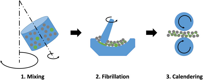
FIGURE 1. Schematic of the three main steps involved in the PTFE-fibrillation process to make dry LiB electrodes. The active material and the PTFE are represented in grey and green respectively.
A large fraction of PTFE fibrillation research has focused on ASSB composite electrodes and SE separators (Hippauf et al., 2019; Zhang et al., 2021; Lee et al., 2023); the fewer studies on LiBs have tended to use relatively large PTFE fractions up to 5wt.% (Zhang et al., 2022; Tao et al., 2023), even though ASSB work has shown lower PTFE fractions (0.2-1 wt.%) can be functional. Nonetheless, all the studies show that PTFE fibrillation is critical to ensure mechanically stable electrodes and SE separators. However, the resulting electrode microstructures are both significantly different to slurry cast equivalents and hard to characterise fully due to the fine-scale nature of the PTFE fibrils. Moreover, how these microstructural differences relate to any performance differences has not been studied in detail.
In this paper we focus on the characterisation of a dry processed LiB electrode microstructure containing a small fraction of PTFE. In particular we resolve the details of the PTFE fibril network at high resolution, before and after cycling. We propose a qualitative model for the origin of the distinctive morphology of the PTFE fibril network. We highlight the microstructural differences between dry-processed and slurry cast electrodes and how these differences influence electrochemical performance.
2 Materials and methods
2.1 Materials
The cathode active material was LiNi0.6Mn0.2Co0.2O2 (NMC622) powder with a median particle size of 10 μm (Targray, Canada) and a typical discharge capacity of 175 mAh/g when cycled between 2.8 and 4.25 V. The polytetrafluoroethylene (PTFE) powder had a particle size between 100 and 200 μm (3M, Germany) and the carbon nanofibres (CNF) for electrical conduction had an average diameter of 150–200 nm and a length of several tens of μm (Pyrograf, United States). For the slurry cast cathodes, the same NMC622 powder was used together with a polyvinylidene fluoride (PVDF) powder (Solvay, Belgium) as binder and C65 carbon black (Timcal, Belgium) as conductive additive.
2.2 Electrode preparation
For the solvent-free process, the active material, binder and carbon nanofibres (CNF) were mixed together in a Thinky planetary mixer for 6 min from 300 up to 2000 rpm before being transferred to an agate mortar. The mortar containing the mixed powders and the pestle were subsequently heated in an oven at 80°C for 20 min, and then mixed manually. After 5 min, a single integral flake was obtained, which was then calendered at a temperature of 80°C and a line pressure of 50 N/mm to approximatively 100 μm thickness using a SUMET CA3 hot calender. Although the processing route described here is typical of the laboratory, it involves the same key steps of shear mixing at elevated temperature followed by compression due to calendering found in industrial pilot lines. The solvent-free processing parameters used here are a result of in-house optimisation based on variations in shearing temperature, volume fraction of constituents, and calendering parameters. The Li4Ti5O12 (LTO) (median particle size 5–10 μm, MSE, United States) counter anodes used in full cells were fabricated using the same solvent-free process. The same LTO anodes were used as counter electrodes for both the solvent-free and slurry cast full cells for consistency. The composition used for electrochemical characterisation of solvent-free electrodes was NMC622 + 1 wt.% PTFE + 3.5 wt.% CNFs. For the microstructural analysis additional NMC622 + 1 wt.% PTFE electrodes were fabricated to more easily focus on the detailed morphology of the PTFE fibrils.
The slurry cast electrodes were manufactured by first mixing the C65 with a stock solution of PVDF/NMP (8% PVDF in NMP) for 5 min using a Thinky planetary mixer. The active material and additional NMP were then added to the mixture to yield a solid content of 60 wt.%, and mixed for a further 10 min in the Thinky mixer to obtain an homogeneous slurry. The slurry was then cast onto a 15 μm thick aluminium current collector using a doctor blade and was dried at 80°C on a hot plate in a fume cupboard. The dried electrodes were finally calendered to reach the target thickness. The composition used for electrochemical characterisation and microstructural analysis of slurry cast electrodes was NMC622 + 2 wt.% PVDF + 2 wt.% C65. The slurry cast electrode fabrication procedure was based on an optimized approach developed across multiple laboratories, and produces performance consistent with electrodes of the same formulation produced in industry (Grant et al., 2022).
2.3 Coin cell assembly
Disks of 14 mm diameter were punched out of the calendered electrodes and dried overnight in a vacuum oven (flushed with Ar) at 120°C. All the slurry cast and solvent-free cathodes had a thickness in the range 100–110 μm and an areal loading of 30–32 mg/cm2 (see Tables S1 and S2 in SI). CR2032 half-cells were assembled with the cathode working against a cleaned and flattened Li chip. CR2032 full-cells were made with the cathode working against the LTO anode. A glass fibres separator (Whatman, United States) was used and the electrolyte was 1 M LiPF6 in ethylene carbonate and dimethyl carbonate (EC/EMC 3/7) + 2wt.% VC (Elyte, Germany). 140 μL of electrolyte was used in the half-cells and 180 μL in full-cells. The coin-cell assembly was performed in a glove box under a high purity Ar atmosphere (O2 < 0.1 ppm) and all the components were dried overnight under vacuum in an antechamber at 80°C. For the full-cells, the cathodes were matched with anodes to give an areal and gravimetric capacity ratio of approximatively 1:1.1. The coin cells were firmly crimped before being taken out of the glovebox for testing.
Three electrodes cells were also prepared for electrochemical impedance spectroscopy (EIS) using El-cell PAT cells with a Li reference electrode and a Li chip as the counter electrode.
2.4 Electrochemical characterisation
Coin cells were tested using a battery cycler (Arbin Instruments, United States) in the potential range of 2.5–4.2 V for NMC-based half-cells at room temperature. The NMC-LTO full cells were cycled in the potential range of 1–2.8 V at room temperature and at a C-rate of C/3. The cells were formed by performing two charge-discharge cycles at C/20 followed by two further cycles at C/10. The cells were charged using a standard CC-CV protocol (the cut-off current was half the current used in the CC step) followed by a CC discharge. For the full-cells the current used for the cycling test was computed based on an assumed cathode theoretical capacity of 175 mAh/g. Impedance measurements were taken at room temperature using a Biologic VSP potentiostat (measurement accuracy ± 0.1%), over the frequency range 100 mHz – 1 kHz with a nominal ac voltage of 10 mV. Data analysis and equivalent circuit fitting was performed using ZVIEW software (ZVIEW-Impedance Software version 4.0c Scribner Associates).
2.5 Microstructure characterisation
The SEM and EDX analysis was performed with a high-resolution Merlin field emission scanning electron microscope (Zeiss, Germany) equipped with an EDX X-max detector (Oxford Instruments, UK) at an accelerating voltage of 3 kV.
3 Results and discussion
LiNi0.6Co0.2Mn0.2O2 (NMC622) based solvent-free Li-ion battery (LiB) electrodes containing 1 wt.%. PTFE binder and 3.5 wt.% carbon nanofibres (CNF) were prepared according to Figure 1 as described in materials and methods. NMC622 was chosen as a representative and well-established cathode material used in the electric vehicle (EV) sector. The typical PVDF-based carbon binder domain (CBD) found in slurry cast electrodes cannot be obtained in solvent-free electrodes, and therefore as is common in the field, CNFs were used to provide the required electrical conductivity. High aspect ratio carbon additives tend to be used in solvent-free electrodes due to their good electronic conductivity and electrical percolation at low volume fraction (Hippauf et al., 2019; Lee et al., 2023; Ryu et al., 2023). The overall composition was chosen after optimisation that involved minimising the binder and carbon fraction while providing a mechanically stable electrode. For comparison, typical NMC622-based slurry cast electrodes using NMP solvent were also fabricated containing 2 wt.% polyvinyldifluoroethylene (PVDF) and 2 wt.% C65 carbon black. Again, compositional optimisation was carried out to minimise binder and carbon fraction.
3.1 Microstructure
The general microstructure of solvent-free electrodes involving PTFE-fibrillation has been reported (Hippauf et al., 2019; Zhang et al., 2021; Grant et al., 2022; Zhang et al., 2022; Lee et al., 2023; Tao et al., 2023) but high resolution fibril characterisation is generally unavailable.
Figures 2A, C show the typical electrode top surface microstructure of the NMC-based solvent-free and slurry cast electrodes prior to calendering, but without any CNFs in the solvent-free electrode so there was no confusion with PTFE fibrils. Corresponding EDX maps in Figures 2B, D reveal the distribution of the active material (blue) obtained from the Ni and O EDX signals and PTFE and PVDF (green) respectively obtained from the F and C EDX signals. Figure 2A shows very fine (
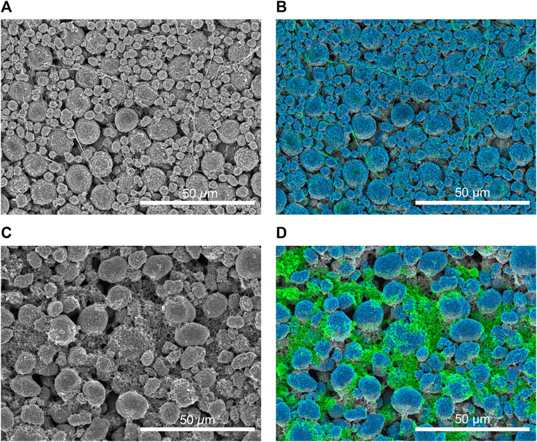
FIGURE 2. Typical microstructures of (A) NMC + 1 wt.% PTFE solvent-free electrode, and (C) NMC + 2 wt.% PVDF + 2 wt.% C65 slurry cast electrode. Respective EDX maps (B, D) showing the distribution of the active material (Ni and O signals in blue) and PTFE and PVDF binders (F and C signals in green).
At higher magnification, Figure 3C shows patches of the PVDF binder covered a significant surface fraction of the NMC particles, and sometimes partially or fully blocked pores that lead into the electrode interior. At further magnification in Figure 3D, the PVDF binder contained the fine carbon C65 particulate to form the carbon binder domain (CBD). For the dry processed electrode, Figure 3A shows a distinct branch-like fibril morphology with much reduced obscuration of the NMC particle surface and no pore blockage. At higher magnification, Figure 3B shows that larger fibrils again branched into extremely fine fibrils of a few 10s of nm or less, forming a 3D fibril net that enmeshes the NMC particles. A further key feature is the way the fibrils are “anchored” to the NMC surface at numerous points. At the macroscale, the fibril web provided an electrode with a flexible and fabric-like handling quality.
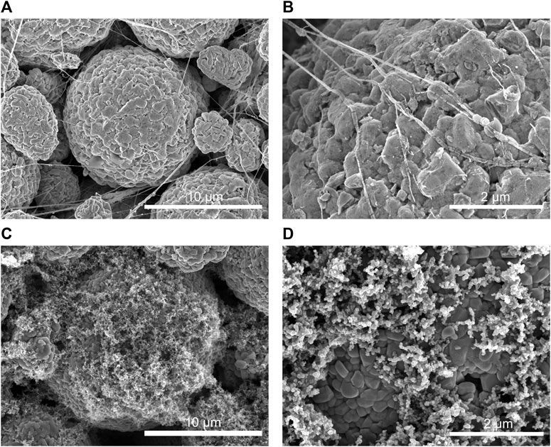
FIGURE 3. Typical microstructures of (A, B) NMC + 1 wt.% PTFE solvent-free electrode, and (C–D) NMC + 2 wt.% PVDF + 2 wt.% C65 slurry cast electrode.
Note that PVDF binder migration to the upper electrode surface during drying is a common feature of slurry cast electrodes, especially when electrodes are dried too quickly. Binder migration can lead to exacerbated pore clogging, restricted electrolyte penetration and inhibited Li ion mobility; it may also cause reduced electrode lifetimes (Westphal et al., 2015; Baunach et al., 2016; Jaiser et al., 2016; Müller et al., 2017; Font et al., 2018; Nikpour et al., 2022). On the other hand, the absence of drying for the solvent-free electrode ensures that binder migration cannot occur, and such problems are avoided.
Based on our many similar observations of the dry processed microstructure, Figure 4A proposes a qualitative model for the formation of the PTFE fibril network and its hierarchical nature. First, during the shear mixing process common to all the fibrillation approaches, The 10–20 μm NMC particles are pressed into the 100–200 μm feedstock PTFE particles. The microscale roughness of the NMC surface readily interlocks with the surface crysallites of the PTFE particles, providing a robust anchor point. An example of this initial adhesion is shown in the inset micrograph by the arrow in Figure 4A. Next, on further mixing and shearing, NMC particles move past and away from one another, leading to the drawing out of the first, relatively large (up to a few μm in diameter) primary fibrils, which can extend over large distances, as shown in Figure 4A.
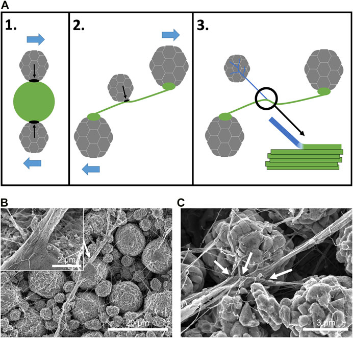
FIGURE 4. (A) Schematic showing the three stages of formation of primary and secondary fibrils during compression and shear mixing of NMC and PTFE. (B) Micrograph showing the formation of a primary fibril with a large PTFE particle being flattened and anchored to the surface of a NMC particle (indicated by the arrow) and drawn out into a large primary fibril composed of a bundle of smaller PTFE strands (inset). (C) Micrograph showing the formation of secondary fibrils. Two smaller NMC particles have drawn out smaller bundles of PTFE strands from a primary fibril to form secondary fibrils (indicated by the arrows).
Ariawan et al. (Ariawan et al., 2002) investigated the paste extrusion of PTFE only powders that were composed of densely packed, connected crystallites. During extrusion, crystallites at the PTFE surface became interlocked, and then as the particles continued to slide past one another, the crystallites “unwound” to form long fibrils. Fibrillation of PTFE only powders has also been suggested to require a combination of compression and shear deformation (Ardakani et al., 2013).
Although the electrodes here used only a small fraction of PTFE powder and shear mixing rather than extrusion, the electrode microstructures suggest the same mechanism of crystallite interlocking and then unwinding is occuring. The relatively rough NMC particle surface in Figure 3B readily provides adhesion and interlocking of the PTFE crystallites. The inset in Figure 4B shows a bundle of fibrils anchored to the surface of a NMC particle.
The freshly formed primary fibrils themselves now interact and adhere to the moving NMC particles as shear mixing continues, drawing, or unwinding, smaller secondary fibrils from the primary fibril, as indicated by the arrows in Figure 4C, creating the branch-like morphology with occasional nodules. This process can repeat to form finer and finer fibrils, without breakage, resulting in a hierarchical web of PTFE fibrils.
3.2 Electrochemical characterisation
The first charge and discharge curves at C/20 for a solvent-free electrode and a slurry cast are shown in Figure 5. The charge-discharge profiles were highly similar, and both consistent with the typical capacity stated by the NMC provider. The solvent-free electrode showed a slightly higher discharge capacity (169 mAh/g compared with 163 mAh/g respectively). The first-charge coulombic efficiencies (CE) were also very similar at 91.1% and 91.3%. As is well known, a CE
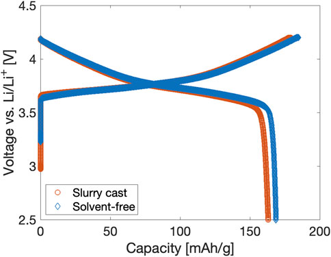
FIGURE 5. First charge and discharge curves at C/20 of solvent-free and slurry cast NMC-based electrodes.
There is not yet consensus on the electrochemical and mechanical stability of the PTFE fibrils in solvent-free electrodes and SE separators. Hippauf et al. suggested that fibrils would break during the compression of their composite NMC-Li6PS5Cl cathodes, mentioning that the PTFE binder did not contribute to the mechanical integrity of the cathode after cell assembly. In contrast, Lee et al. (Lee et al., 2023) observed a dense network of PTFE fibrils in their Li6PS5Cl SE separator even after extensive calendering and concluded that PTFE was instrumental to the mechanical stability of their SE separator. Zhang et al. (Zhang et al., 2022) could not observe any fibrils in their PTFE-graphite anode after cycling and concluded that PTFE fibrils were unstable at anodic potentials and reduced to carbyne during the first lithiation process. However, others reported stable cycling behaviour in graphite anodes based on a PTFE binder (Manev et al., 1995; Novfik et al., 1997).
Post-cycling microstructural analysis was carried out on the solvent-free NMC based electrodes after a charge/discharge rate test consisting of 30 cycles from 0.1C up to 2C, then back to 0.1C. Figure 6A shows that the fibrils are still clearly observed after cycling, confirming the stability of the PTFE network during cell assembly/disassembly and after 30 charge-discharge cycles. In this case, CNFs were also present and were similarly enmeshed in the PTFE fibril network. Typical PTFE fibrils and CNFs are identified by the green and orange arrows in Figure 6A. For comparison, the typical microstructure of a slurry cast cathode cycled under the same conditions is also presented in Figure 6B. The PVDF + C65 CBD domains are clearly identified after cycling and have the same morphology as the pristine slurry cast electrode shown in Figure 3C (the CBD distribution was confirmed by EDX elemental analysis in Supplementary Figure S1).
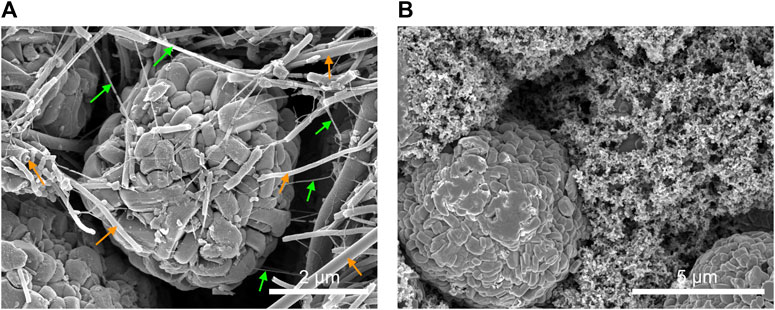
FIGURE 6. Typical microstructure of (A) cycled solvent-free NMC-based electrode containing 1 wt.% PTFE and 3.5 wt.% CNF and (B) cycled slurry cast electrode composed of 2 wt.% PVDF and 2 wt.% C65 (30 charge-discharge cycles at rates between 0.1C and 2C). The green and orange arrows in (A) indicate typical PTFE fibrils and CNFs, respectively.
Figure 7A shows the discharge capacity of the solvent-free and slurry cast NMC based electrodes at charge/discharge rates from 0.1C up to 2C. The electrodes had similar thickness and aerial loading (further details are provided in Supplementary Table S1) to provide a fair comparison. As expected, all electrodes showed reduced capacity with increasing C rate, but the solvent-free electrodes performed slightly better than slurry cast equivalents over the C-rate range investigated. The difference in discharge capacities increased with C-rate, with improvements in the average discharge capacity of the solvent-free electrode of 4.5% at 0.1C, 6% at 0.2C, 10% at 0.5C, 27% at 1C and 146% at 2C. Thus even at the lowest rates, the microstructural differences were sufficient for the solvent-free electrodes to deliver an extra 5%–10% capacity.
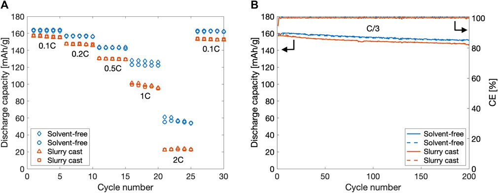
FIGURE 7. (A) Discharge capacity of solvent-free and slurry cast cathodes at different C-rates in half-cell configuration (against Li metal). (B) Discharge capacity (left) and coulombic efficiency (right) of solvent-free and slurry cast cathodes at C/3 in full-cell configuration (against LTO).
Figure 7B shows the cycling stability of self-standing solvent-free and slurry cast cathodes in a full cell configuration (NMC-LTO) over 200 cycles at C/3. The solvent-free electrodes had an average capacity retention of 96% compared with 93% for the slurry cast electrodes, corresponding to a degradation rate of 0.02%/cycle and 0.035%/cycle respectively.
The higher discharge capacity and improved cycling response of the solvent-free electrodes may originate from reduced charge transfer resistance and/or higher ionic mobility. Therefore, electrochemical impedance spectroscopy (EIS) was performed on both electrode types in a three-electrode arrangement. Figure 8A shows their impedance response comprised a broad arc with a curved tail at low frequency. Qualitatively, this shape is typical of insertion cathode materials (Atebamba et al., 2010; Alavi et al., 2015; Meddings et al., 2020). Figure 8B shows the same data in a spectroscopic capacitance plot and three plateaux can be identified at high (1 kHz), intermediate (10–100 Hz) and low (100 mHz) frequency. With reference to a detailed study of similar materials in (Atebamba et al., 2010), the three plateaus were attributed to (from high to low frequencies) contact resistance with the current collector, double layer capacitance and its related Li insertion resistance, and finally the Li ion diffusion through the electrode pores. Each of these electrochemical processes can be identified by a time constant τ, defined as τ = RC, where R and C are the resistance and capacitance (Atebamba et al., 2010; Alavi et al., 2015). An equivalent circuit analysis was performed using the circuit in Figure 8A, and the best-fit to the data also shown in Figure 8A.
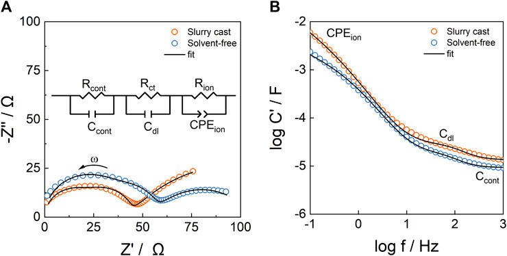
FIGURE 8. (A) Nyquist plot of solvent-free and slurry cast NMC-based electrodes (in the discharged state) in a 3 electrode arrangement with inset equivalent circuit used for best-fit modelling. (B) Spectroscopic capacitance plot of the same data and best-fit to the data from the equivalent circuit in (A).
The best-fit resistances are presented in Table 1 and indicated that the contact resistance of the solvent-free electrode (36 Ω) was larger than the slurry cast electrode (25 Ω), probably because the solvent-free electrode was not formed onto a current collector. The charge transfer resistance were similar (18 and 21 Ω), but the ionic diffusion resistance was significantly lower (50 vs. 114 Ω), in the solvent-free electrode. As shown previously, in the slurry cast electrodes there were large patches of CBD covering a significant fraction of the NMC particle surface and some pore blockage (Figure 3C). In contrast, the solvent-free electrodes had no pore blockage and minimal NMC surface obscuration (Figure 3A), enabling charge transfer at the NMC/electrolyte interface and, most notably, improved ionic mobility through the electrode pores, which dominated capacity at higher C rates (Besnard et al., 2017). At the lowest C-rates, ionic mobility plays a more limited role in controlling capacity, and the modest 5%–10% improvements in the capacity of the solvent-free electrodes likely originated from their slightly lower charge transfer resistance.
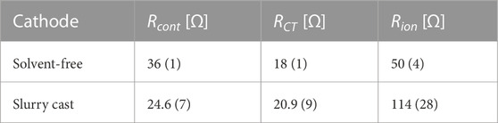
TABLE 1. Resistances obtained from an equivalent circuit analysis and corresponding to the best-fit curves shown in Figure 8A.
4 Conclusion
Solvent-free manufacturing can offer significant environmental, safety, cost and operational advantages over slurry casting for the manufacture of Li-ion battery and similar electrodes. A comprehensive comparison of solvent-free NMC based electrodes with conventional slurry cast electrodes of similar thickness (100 μm) and areal loading (30–32 mAh/cm2) has shown significant microstructural differences and corresponding differences in electrochemical response. High resolution microscopy designed to probe the PTFE fibrils critical to solvent-free electrodes revealed a complex hierarchical morphology distinct from the mossy carbon binder domain of slurry cast electrodes. Repeated PTFE-fibrillation caused by PTFE anchoring onto the NMC surface followed by unwinding of crystalline units from PTFE powders led to a hierarchical branch-like morphology. Large primary fibrils of a few microns in diameter and hundreds of microns in length branched into finer secondary and ever finer fibrils down to diameters of tens of nanometers. The hierarchy of fibrils formed a web-like structure throughout the electrode, providing a cloth-like texture even at a fraction as low as 1 wt.% of PTFE.
Electrochemical investigation showed that solvent-free electrodes had better rate performance over the C-rate range 0.1C–2C, and in particular, at the highest rate the discharge capacity increased by 150% compared with the slurry cast equivalent; solvent-free electrodes also degraded 40% slower and retained 96% of their initial capacity after 200 cyles at C/3. Electrochemical impedance spectroscopy and equivalent circuit modelling revealed that the charge transfer and particularly the ionic diffusion resistances were reduced in the solvent-free electrodes. The solvent-free electrodes had minimal obscuration of the active material surface and no pore blockage.
Even if solvent-free and slurry cast performance were essentially similar, the cost, simplicity and safety advantages of solvent-free electrodes could be compelling. However, our results suggest that there may also be electrochemical performance benefits in Li-ion battery cathode applications. Nonetheless, challenging the ubiquity and high productivity of slurry casting, will require ensuring that the benefits at laboratory scale can be translated to a productive, high yield manufacturing environment.
Data availability statement
The original contributions presented in the study are included in the article or Supplementary Material, further inquiries can be directed to the corresponding author.
Author contributions
GM: Writing–original draft, Writing–review and editing. SW: Writing–review and editing. JR-G: Writing–original draft, Writing–review and editing. PG: Writing–original draft, Writing–review and editing.
Funding
The author(s) declare financial support was received for the research, authorship, and/or publication of this article. The authors would like to thank the Faraday Institution for financial support through grant “Nextrode-next-generation electrodes” (FIRG015 and FIRG066).
Acknowledgments
The authors acknowledge the use of characterisation facilities within the David Cockayne Centre for Electron Microscopy, Department of Materials, University of Oxford.
Conflict of interest
The authors declare that the research was conducted in the absence of any commercial or financial relationships that could be construed as a potential conflict of interest.
Publisher’s note
All claims expressed in this article are solely those of the authors and do not necessarily represent those of their affiliated organizations, or those of the publisher, the editors and the reviewers. Any product that may be evaluated in this article, or claim that may be made by its manufacturer, is not guaranteed or endorsed by the publisher.
Supplementary material
The Supplementary Material for this article can be found online at: https://www.frontiersin.org/articles/10.3389/fenrg.2023.1336344/full#supplementary-material
References
Alavi, S. M., Birkl, C. R., and Howey, D. A. (2015). Time-domain fitting of battery electrochemical impedance models. J. Power Sources 288, 345–352. doi:10.1016/j.jpowsour.2015.04.099
Almar, L., Joos, J., Weber, A., and Ivers-Tiffée, E. (2019). Microstructural feature analysis of commercial li-ion battery cathodes by focused ion beam tomography. J. Power Sources 427, 1–14. doi:10.1016/j.jpowsour.2019.04.019
Al-Shroofy, M., Zhang, Q., Xu, J., Chen, T., Kaur, A. P., and Cheng, Y. T. (2017). Solvent-free dry powder coating process for low-cost manufacturing of lini1/3mn1/3co1/3o2 cathodes in lithium-ion batteries. J. Power Sources 352, 187–193. doi:10.1016/j.jpowsour.2017.03.131
Ardakani, H. A., Itsoulis, E. M., and Atzikiriakos, S. G. H. (2013). Regular contributed articles polytetrafluoroethylene paste extrusion: af ibrillation model and its relation to mechanical properties.
Ariawan, A. B., Ebnesajjad, S., and Hatzikiriakos, S. G. (2002). Paste extrusion of polytetrafluoroethylene (ptfe) fine powder resins. Can. J. Chem. Eng. 80, 1153–1165. doi:10.1002/cjce.5450800617
Atebamba, J.-M., Moskon, J., Pejovnik, S., and Gaberscek, M. (2010). On the interpretation of measured impedance spectra of insertion cathodes for lithium-ion batteries. J. Electrochem. Soc. 157, A1218. doi:10.1149/1.3489353
Balbuena, P. B., and Wang, Y. X. (2004). Lithium-ion batteries: solid-electrolyte interphase. World Scientific.
Baunach, M., Jaiser, S., Schmelzle, S., Nirschl, H., Scharfer, P., and Schabel, W. (2016). Delamination behavior of lithium-ion battery anodes: influence of drying temperature during electrode processing. Dry. Technol. 34, 462–473. doi:10.1080/07373937.2015.1060497
Besnard, N., Etiemble, A., Douillard, T., Dubrunfaut, O., Tran-Van, P., Gautier, L., et al. (2017). Multiscale morphological and electrical characterization of charge transport limitations to the power performance of positive electrode blends for lithium-ion batteries. Adv. Energy Mater. 7, 4. doi:10.1002/aenm.201602239
de la Torre-Gamarra, C., Sotomayor, M. E., Sanchez, J. Y., Levenfeld, B., Várez, A., Laïk, B., et al. (2020). High mass loading additive-free lifepo4 cathodes with 500 microns thickness for high areal capacity li-ion batteries. J. Power Sources 458, 5. doi:10.1016/j.jpowsour.2020.228033
Entwistle, J., Ge, R., Pardikar, K., Smith, R., and Cumming, D. (2022). Carbon binder domain networks and electrical conductivity in lithium-ion battery electrodes: a critical review, 9.
Font, F., Protas, B., Richardson, G., and Foster, J. M. (2018). Binder migration during drying of lithium-ion battery electrodes: modelling and comparison to experiment. J. Power Sources 393, 177–185. doi:10.1016/j.jpowsour.2018.04.097
Forytta, M. (2021). Environmentally friendly manufacture of battery electrodes sustainable battery production, 9.
Grant, P. S., Greenwood, D., Pardikar, K., Smith, R., Entwistle, T., Middlemiss, L. A., et al. (2022). Roadmap on li-ion battery manufacturing research. JPhys Energy 4, 042006. doi:10.1088/2515-7655/ac8e30
Hawley, W. B., Parejiya, A., Bai, Y., Meyer, H. M., Wood, D. L., and Li, J. (2020). Lithium and transition metal dissolution due to aqueous processing in lithium-ion battery cathode active materials. J. Power Sources 466, 228315. doi:10.1016/j.jpowsour.2020.228315
Hippauf, F., Schumm, B., Doerfler, S., Althues, H., Fujiki, S., Shiratsushi, T., et al. (2019). Overcoming binder limitations of sheet-type solid-state cathodes using a solvent-free dry-film approach. Energy Storage Mater. 21, 390–398. doi:10.1016/j.ensm.2019.05.033
Jaiser, S., Müller, M., Baunach, M., Bauer, W., Scharfer, P., and Schabel, W. (2016). Investigation of film solidification and binder migration during drying of li-ion battery anodes. J. Power Sources 318, 210–219. doi:10.1016/j.jpowsour.2016.04.018
Lee, D. J., Jang, J., Lee, J. P., Wu, J., Chen, Y. T., Holoubek, J., et al. (2023). Physio-electrochemically durable dry-processed solid-state electrolyte films for all-solid-state batteries. Adv. Funct. Mater. 7. doi:10.1002/adfm.202301341
Li, Y., Wu, Y., Wang, Z., Xu, J., Ma, T., Chen, L., et al. (2022). Progress in solvent-free dry-film technology for batteries and supercapacitors, 5.
Liu, Y., Zhang, R., Wang, J., and Wang, Y. (2021). Current and future lithium-ion battery manufacturing. iScience 24, 102332. doi:10.1016/j.isci.2021.102332
Lu, Y., Zhao, C. Z., Yuan, H., Hu, J. K., Huang, J. Q., and Zhang, Q. (2022). Dry electrode technology, the rising star in solid-state battery industrialization, 3.
Ludwig, B., Zheng, Z., Shou, W., Wang, Y., and Pan, H. (2016). Solvent-free manufacturing of electrodes for lithium-ion batteries. Sci. Rep. 6, 23150. doi:10.1038/srep23150
Manev, V., Naidenov, I., Puresheva, B., Zlatilova, P., and Pistoia, G. (1995). Electrochemical performance of natural brazilian graphite as anode material for lithium-ion rechargeable cells.
Meddings, N., Heinrich, M., Overney, F., Lee, J. S., Ruiz, V., Napolitano, E., et al. (2020). Application of electrochemical impedance spectroscopy to commercial li-ion cells: a review, 12.
Müller, M., Pfaffmann, L., Jaiser, S., Baunach, M., Trouillet, V., Scheiba, F., et al. (2017). Investigation of binder distribution in graphite anodes for lithium-ion batteries. J. Power Sources 340, 1–5. doi:10.1016/j.jpowsour.2016.11.051
Nikpour, M., Liu, B., Minson, P., Hillman, Z., Mazzeo, B. A., and Wheeler, D. R. (2022). Li-ion electrode microstructure evolution during drying and calendering. Batteries 8, 107. doi:10.3390/batteries8090107
Novfik, P., Scheifele, W., Winter, M., and Haas, O. (1997). Power sources graphite electrodes with tailored porosity for rechargeable ion-transfer batteries.
Ryu, M., Hong, Y. K., Lee, S. Y., and Park, J. H. (2023). Ultrahigh loading dry-process for solvent-free lithium-ion battery electrode fabrication. Nat. Commun. 14, 1316. doi:10.1038/s41467-023-37009-7
Schälicke, G., Landwehr, I., Dinter, A., Pettinger, K. H., Haselrieder, W., and Kwade, A. (2020). Solvent-free manufacturing of electrodes for lithium-ion batteries via electrostatic coating. Energy Technol. 8, 2. doi:10.1002/ente.201900309
Sotomayor, M. E., de la Torre-Gamarra, C., Levenfeld, B., Sanchez, J. Y., Varez, A., Kim, G. T., et al. (2019). Ultra-thick battery electrodes for high gravimetric and volumetric energy density li-ion batteries. J. Power Sources 437, 226923. doi:10.1016/j.jpowsour.2019.226923
Sotomayor, M. E., Torre-Gamarra, C. D. L., Bucheli, W., Amarilla, J. M., Varez, A., Levenfeld, B., et al. (2018). Additive-free li4ti5o12 thick electrodes for li-ion batteries with high electrochemical performance. J. Mater. Chem. A 6, 5952–5961. doi:10.1039/c7ta10683a
Tao, R., Steinhoff, B., Sun, X. G., Sardo, K., Skelly, B., Meyer, H. M., et al. (2023). High-throughput and high-performance lithium-ion batteries via dry processing. Chem. Eng. J. 471, 144300. doi:10.1016/j.cej.2023.144300
Verma, P., Maire, P., and Novák, P. (2010). A review of the features and analyses of the solid electrolyte interphase in li-ion batteries, 9.
Westphal, B., Bockholt, H., Günther, T., Haselrieder, W., and Kwade, A. (2015). Influence of convective drying parameters on electrode performance and physical electrode properties. ECS Trans. 64, 57–68. doi:10.1149/06422.0057ecst
Zhang, Y., Huld, F., Lu, S., Jektvik, C., Lou, F., and Yu, Z. (2022). Revisiting polytetrafluorethylene binder for solvent-free lithium-ion battery anode fabrication. Batteries 8, 57. doi:10.3390/batteries8060057
Zhang, Y., Lu, S., Wang, Z., Volkov, V., Lou, F., and Yu, Z. (2023). Recent technology development in solvent-free electrode fabrication for lithium-ion batteries, 9.
Zhang, Z., Wu, L., Zhou, D., Weng, W., and Yao, X. (2021). Flexible sulfide electrolyte thin membrane with ultrahigh ionic conductivity for all-solid-state lithium batteries. Nano Lett. 21, 5233–5239. doi:10.1021/acs.nanolett.1c01344
Keywords: solvent-free electrodes, Li-ion batteries (LIBs), PTFE fibrils, dry processing, electrode manufacturing, NMC cathodes, PTFE binder, microstructure
Citation: Matthews GAB, Wheeler S, Ramírez-González J and Grant PS (2024) Solvent-free NMC electrodes for Li-ion batteries: unravelling the microstructure and formation of the PTFE nano-fibril network. Front. Energy Res. 11:1336344. doi: 10.3389/fenrg.2023.1336344
Received: 10 November 2023; Accepted: 13 December 2023;
Published: 11 January 2024.
Edited by:
Mona Faraji Niri, University of Warwick, United KingdomReviewed by:
Carl David Reynolds, University of Birmingham, United KingdomSamuel Cooper, Imperial College London, United Kingdom
Copyright © 2024 Matthews, Wheeler, Ramírez-González and Grant. This is an open-access article distributed under the terms of the Creative Commons Attribution License (CC BY). The use, distribution or reproduction in other forums is permitted, provided the original author(s) and the copyright owner(s) are credited and that the original publication in this journal is cited, in accordance with accepted academic practice. No use, distribution or reproduction is permitted which does not comply with these terms.
*Correspondence: G. A. B. Matthews, Z3VpbGxhdW1lLm1hdHRoZXdzQG1hdGVyaWFscy5veC5hYy51aw==