 Tianjiao Huang1
 Wu Xia
 Fnu Joshua
 Ao Yu
Ao Yu- 1College of Chemistry and Chemical Engineering, Jishou University, Jishou, China
- 2NanoScience Technology Center, University of Central Florida, Orlando, FL, United States
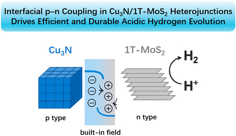
Rational interfacial engineering is crucial to designing non-precious electrocatalysts for the hydrogen evolution reaction (HER). Here we report a Cu3N/1T-MoS2 heterojunction in which ultrathin 1T-MoS2 nanosheets are conformally grown on conductive p-type Cu3N nanocubes. Spectroscopy and microscopy reveal intimate lattice contact and interfacial strain, while XPS indicates charge redistribution across the junction. In 0.5 M H2SO4, the optimized 1:1 composite delivers an overpotential of 387 mV at 50 mA cm−2 and a Tafel slope of 57 mV dec−1, outperforming both constituents (MoS2 ≈ 456 mV; Cu3N inactive at this current density). Continuous operation for 150 h demonstrates excellent acid stability. Electrochemical impedance and double-layer capacitance analyses show the lowest charge-transfer resistance and the highest electrochemically active surface area among all samples (Cdl = 103.6 mF cm−2), corroborating rapid electron transport and abundant accessible sites. The activity enhancement arises from a p–n heterojunction with a built-in field that promotes directional electron flow to MoS2 active edges, together with strain-induced defect exposure. This work identifies Cu3N as an effective platform to stabilize conductive MoS2 and provides design rules for interface-engineered HER catalysts.
1 Introduction
Hydrogen is a versatile clean-energy carrier crucial for deep decarbonization across chemicals, transportation, and grid storage (Ayodele et al., 2019; Li et al., 2020; McHugh et al., 2020; Sun et al., 2023). Electrochemical water splitting (Sun Y. et al., 2021) offers a modular, high-purity route to hydrogen (H2) when powered by renewables, but cost-effective deployment still requires non-precious electrocatalysts that combine low overpotentials, high current densities, and long-term stability − requirements that remain a major challenge (Boretti et al., 2021; Li et al., 2016; Sun H. et al., 2021; Vasiliadou et al., 2018).
Among non-precious metal candidates, transition-metal dichalcogenides (TMDs) are promising for the hydrogen evolution reaction (HER) (Chia et al., 2015; Liu et al., 2019; Meshesha et al., 2023; Rao et al., 2021; Xue et al., 2022). Molybdenum disulfide (MoS2) is particularly attractive owing to its tunable chemistry and edge-site activity, yet performance is constrained by the largely inert basal plane of semiconducting 2H-MoS2 and by limited in-plane conductivity. Metallic 1T-MoS2 improves conductivity and increases the population of active sites, but it is metastable under operating conditions and prone to activity decay (Amiinu et al., 2017; Chiu et al., 2024). Conventional remedies − defect/phase engineering, heteroatom doping, and conductive supports − can accelerate kinetics but often compromise stability or require complex syntheses (Gong et al., 2023; Jin et al., 2025; Liu et al., 2020; Miao et al., 2024).
To overcome these limitations, we couple p-type copper nitride (Cu3N) with 1T-MoS2 (Kwon et al., 2025). Cu3N is an attractive yet underexplored semiconductor with good conductivity, nitrogen-vacancy-rich cubic lattices, and a moderate work function (Gan et al., 2022; Wang et al., 2023; Zhang et al., 2021; Zhu et al., 2020a), enabling rapid carrier transport and scalable synthesis, enabling a p-n heterojunction with a built-in field that directs electrons to MoS2 edge sites while extracting holes into Cu3N, thereby enhancing charge separation and accelerating HER kinetics. Strong interfacial coupling further stabilizes the 1 T phase of MoS2, and favorable adsorption/transport characteristics support high-current, durable operation (Du et al., 2022; Jin et al., 2025; Wang et al., 2024). Compared with recent MoS2-based heterojunctions (typically n–n or metal–semiconductor pairings, Supplementary Table S1), the Cu3N/1 T-MoS2 architecture combines directional charge transfer, noble-metal-free electronic wiring, improved 1T-phase stability, and robust acidic performance.
In this work, Cu3N/1T-MoS2 achieves η50 = 387 mV (under 50 mA cm−2 of current density) and a Tafel slope of 57 mV dec−1 in 0.5 M H2SO4, maintaining performance for 150 h, demonstrating advantages in comprehensive performance. These results highlight the benefits of p-n interfacial coupling and the built-in field in funneling electrons to MoS2 edge sites, delivering mechanism-anchored gains in both kinetics and durability, and offering a simple, non-precious route toward practical HER catalysts1.
2 Materials and methods
2.1 Chemicals
All reagents were of analytical grade and used without further purification. Sodium hydroxide (NaOH, 95%) was purchased from Macklin Biochemical Technology Co., Ltd. Hydrochloric acid (HCl, 36%) and sulfuric acid (H2SO4, 98%) were obtained by Hunan Huihong Reagent Co., Ltd. Ammonium heptamolybdate tetrahydrate ((NH4)6Mo7O24·4H2O, 99%) and thiourea (CH4N2S) were supplied from Sinopharm Chemical Reagent Co., Ltd. Copper (II) acetate monohydrate (Cu(OAc)2·H2O, 99%) and potassium hydroxide (KOH, 95%) were obtained from Aladdin Biochemical Technology Co., Ltd. Urea (CH4N2O, 99%) was acquired from Xilong Scientific Co., Ltd.
2.2 Synthesis of Cu3N
Cu3N was synthesized via a chemical vapor deposition route. Specifically, 0.33 g of Cu(OAc)2·H2O and 0.50 g of urea were separately placed in two porcelain boats. The precursors were heated to 300 °C at a ramp rate of 5 °C·min-1 under a continuous Ar flow (40 sccm) and maintained for 2 h. After cooling to room temperature, the black powder was collected, washed with deionized water (3 × 50 mL) and ethanol (3 × 50 mL) successively, and dried under vacuum at 60 °C for 12 h (Mondal and Raj, 2018).
2.3 Synthesis of MoS2
1 T phase MoS2 was synthesized following a modified hydrothermal procedure. Briefly, 1.25 g ammonium heptamolybdate tetrahydrate ((NH4)6Mo7O24·4H2O, 1.0 mmol) and 2.28 g thiourea (30.0 mmol) were dissolved in 35 mL deionized water and stirred for 30 min. The homogeneous solution was transferred to a 100 mL Teflon-lined stainless-steel autoclave, sealed, and heated at 180 °C for 24 h. After cooling, the resulting black precipitate was separated by centrifugation (6,000 rpm, 10 min per cycle), washed thoroughly with deionized water and ethanol, and vacuum-dried at 60 °C for 12 h (Wang et al., 2020).
2.4 Synthesis of Cu3N/MoS2 composites
To synthesize the Cu3N/MoS2(1:1) composite, 0.21 g of Cu3N (1.0 mmol), 0.54 g (NH4)6Mo7O24·4H2O (0.43 mmol), and 0.98 g thiourea (12.87 mmol) were dispersed in 35 mL of deionized water with stirring for 30 min. The mixture was sealed in a 100 mL Teflon-lined autoclave and subjected to hydrothermal treatment at 180 °C for 24 h. After natural cooling, the solid product was collected by centrifugation, washed with water and ethanol successively for three times, and dried under vacuum at 60 °C for 12 h. Additional composites with Cu3N/MoS2 of 1:0.5 and 1:2 were prepared under identical conditions.
2.5 Electrode preparation
Catalyst inks were prepared by dispersing 2.5 mg of Cu3N/MoS2 powder in 400 μL ethanol and 90 μL deionized water, followed by ultrasonication to achieve a homogeneous suspension. Then, 10 μL of Nafion® 117 solution (∼5 wt%) was added, and the mixture was sonicated again. A 6 μL aliquot of the resulting ink was drop-cast onto a glassy carbon electrode (GCE, 3 mm diameter), yielding a loading of ∼0.4 mg cm-2. The electrode was dried at ambient temperature prior to electrochemical testing.
2.6 Characterization
X-ray diffraction (XRD) was performed on a TD-3500 diffractometer using Cu Kα radiation (λ = 0.15406 nm), scanned over a 2θ range of 5°–90° with a scan rate of 2.4°·min−1. X-ray photoelectron spectroscopy (XPS) was carried out on a Thermo Scientific K-Alpha spectrometer equipped with an Al Kα source (hν = 1486.6 eV). Scanning electron microscopy (SEM) and energy-dispersive X-ray spectroscopy (EDS) were conducted on a ZEISS Sigma 300 microscope using INLENS and ET detectors. Transmission electron microscopy (TEM) and EDS mapping were conducted using a JEOL JEM-F200 system equipped with JED-2300T.
2.7 Electrochemical measurements
Electrochemical HER measurements were conducted in 0.5 M H2SO4 (pH ≈ 0.34) using a three-electrode setup: the modified GCE as the working electrode, a graphite rod as the counter electrode, and an Ag/AgCl (3 M KCl) electrode as the reference. Linear sweep voltammetry (LSV) was recorded at 5 mV s-1 with 90% iR compensation. Potentials were converted to the reversible hydrogen electrode (RHE) scale using related formula (ERHE = EAg/AgCl + 0.0592 pH + 0.197 V). Tafel slopes were derived from LSV curves. Electrochemical impedance spectroscopy (EIS) was conducted at an overpotential of 387 mV over the frequency range of 0.1 Hz–100 kHz. The electrochemically active surface area (ECSA) was estimated from the double-layer capacitance (Cdl), obtained via cyclic voltammetry (CV) at scan rates of 5–25 mV s-1 within the non-Faradaic potential window (0.2175–0.3175 V vs. RHE).
3 Results and discussion
Scanning-electron-microscopy (SEM) images for pristine Cu3N and for Cu3N/MoS2 composites obtained with Cu3N-to-Mo precursors of 1:0.5, 1:1 and 1:2 are compiled, while the corresponding energy-dispersive X-ray spectroscopy (EDS) elemental maps for the 1:1 sample are presented in Figures 1c,d, Supplementary Figure S1B. The as-synthesized Cu3N consists of smooth cubes. The narrow size distribution and sharp edges corroborate the phase purity inferred from XRD (Figure 2a) (Mallick et al., 2024; Mondal and Raj, 2018).
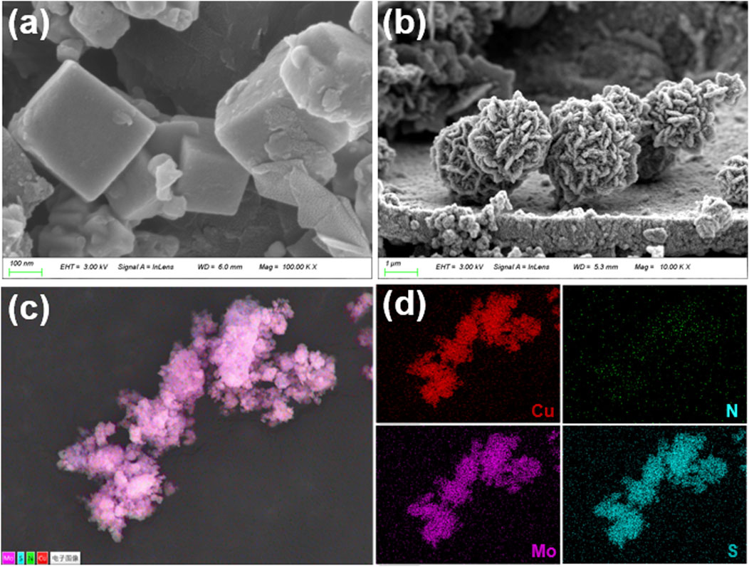
Figure 1. SEM of (a) Cu3N, and (b) Cu3N/MoS2(1:1). (c) and (d) EDS of Cu3N/MoS2(1:1) with Cu, Mo, N and S elements.
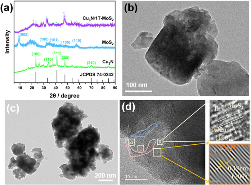
Figure 2. (a) XRD patterns of Cu3N, MoS2 and Cu3N/MoS2(1:1). (b) TEM of Cu3N. (c) TEM of Cu3N/MoS2(1:1). (d) HRTEM of Cu3N/MoS2(1:1) with characteristic lattice fringes.
Introducing a limited amount of Mo precursor leads to the nucleation of ultrathin MoS2 nanosheets directly on the Cu3N cubes. The flakes anchor preferentially on the vertices and edges, giving rise to a rough texture while preserving the underlying cubic morphology (Figures 1a,b, Supplementary Figures S1C, D). At a stoichiometric precursor ratio, MoS2 growth becomes self-sustaining, producing densely packed, radially oriented nanosheets that coalesce into rose-like microflowers (overall diameter 0.8–2 µm). Each flower encloses a Cu3N core that is completely obscured by the MoS2 shell, suggesting a core-shell or yolk-shell heterostructure (Chiu et al., 2024; Gong et al., 2023). The hierarchical porosity created by the inter-flake voids is expected to facilitate electrolyte infiltration and accelerate mass transport in electrocatalytic operation. Further increasing the Mo precursor leads to excessive MoS2 deposition. Thick, entangled nanosheets (∼20 nm) intergrow into open networks that protrude several hundred nanometers from the core. Although this architecture maximizes the content of MoS2, it may compromise electronic coupling to the Cu3N core and partially block ion channels, underscoring the need for stoichiometric optimization (Supplementary Figures S1C, D). Element-specific signals for Cu, N, Mo and S are co-distributed throughout the 1:1 heterostructure. The Cu and N maps coincide with the core region, whereas Mo and S extend uniformly over the entire flower-like particle, confirming the conformal growth of MoS2 on Cu3N. No extraneous elements are detected, attesting to the chemical integrity of the composite (Figures 1c,d). The systematic evolution from sparsely decorated cubes to fully encapsulated core-shell flowers demonstrates that MoS2 nucleation and growth can be finely tuned by the Cu3N: Mo precursor ratio. These morphological attributes rationalize the superior electrochemical performance discussed in next section.
The crystal structures of Cu3N, MoS2, and Cu3N/MoS2 heterojunction were analyzed by X-ray diffraction (XRD) (Figure 2a). Distinct reflections at 23.2°, 33.2°, 41.0° and 47.7° are assigned to the (100) (110), (111), and (200) planes of cubic Cu3N (JCPDS No. 74-0242), confirming phase purity (Mallick et al., 2024; Mondal and Raj, 2018). The MoS2 sample shows reflections at 33°, 49°, and 58° for the (100) (105), and (110) planes of the 1 T phase, with additional peaks at 19° and 43° further indicating 1 T formation. A broad basal reflection centred at 9.5° corresponds to an interlayer spacing of d002 = 0.93 nm, markedly larger than the 0.62 nm of bulk 2H-MoS2. Such expansion is characteristic of the 1 T polymorph generated by chemical exfoliation or intercalation-driven electron injection (Jayabal et al., 2018; Wang et al., 2020; Yu et al., 2018). All fingerprint peaks of both parent lattices are retained in Cu3N/MoS2 composite, indicating that hydrothermal assembly proceeds without alloying or oxide/sulfide by-products. The peak shifts of Cu3N(111) (41.0° → 40.78°) and MoS2(100) (33.0° → 33.26°), together with line broadening, indicate strong interfacial interactions between Cu3N and MoS2, further corroborated by TEM and XPS analyses.
Transmission-electron microscopy (TEM) was employed to visualize the crystal architecture of pristine Cu3N (Figure 2b) and of the Cu3N/MoS2(1:1) heterostructures synthesised with Cu3N: Mo precursor ratios of 1:1 (Figure 2c). Low-magnification images reveal monodisperse nanocubes (Figure 2b). Lattice fringes of 0.19 nm assigned to the Cu3N (200) planes extend coherently before intersecting with 0.32 nm fringes originating from the MoS2 (100) planes (Figure 2d) (Jayabal et al., 2018; Mallick et al., 2024; Mondal and Raj, 2018; Wang et al., 2020; Yu et al., 2018). The acute intersection angle (≈90°) reveals a semi-coherent interface, indicating epitaxial alignment despite the large symmetry mismatch between cubic Cu3N and hexagonal MoS2. No amorphous halos or disordered fringe terminations are detected, indicating that the hydrothermal overgrowth does not induce grain-boundary amorphisation. The absence of misfit dislocations within the examined field further supports coherent, low-defect bonding.
Supplementary Figures S3a, b displays the selected-area electron-diffraction (SAED) pattern acquired from an individual Cu3N nanocube, fully corroborating the XRD results (Figure 2a). The pattern shows discrete, azimuthally discontinuous spots arranged on concentric rings rather than continuous Debye–Scherrer rings (Jiang et al., 2014; Mallick et al., 2024; Mondal and Raj, 2018). This indicates that the probed area contains a limited number of well-oriented crystallites–consistent with monocrystalline cubes observed by TEM–rather than a random powder. The SAED analysis substantiates that the as-synthesized Cu3N nanocubes are highly crystalline, phase-pure and possess long-range order–prerequisites for achieving intimate electronic contact and efficient charge transfer in the Cu3N/MoS2 heterostructures discussed in the subsequent sections. Supplementary Figures S3b presents the SAED pattern collected from a single Cu3N/MoS2 particle synthesized at the optimal Cu3N: Mo precursor ratio of 1:1. In contrast to the spot-like pattern of pristine Cu3N (Supplementary Figures S3a), the composite exhibits a series of nearly continuous diffraction rings populated by discrete spots, reflecting the coexistence of a highly ordered Cu3N core and a polycrystalline shell of few-layer MoS2 nanosheets with random in-plane orientation. All diffraction maxima can be indexed exclusively to Cu3N and metallic 1T-MoS2, confirming the phase purity inferred from XRD. The innermost rings (2.6, 3.7, 4.5 nm−1) are dominated by discrete spots rather than continuous arcs, indicative of a single-crystalline Cu3N core whose zone axis is preserved across the illuminated area (Jayabal et al., 2018; Mallick et al., 2024; Mondal and Raj, 2018; Wang et al., 2020; Yu et al., 2018). In contrast, the outer rings (3.2, 5.2, 6.2 nm-1) are quasi-continuous, signifying that the MoS2 shell is composed of numerous nanoflakes with random azimuthal distribution–fully consistent with the radially oriented “rose-like” nanosheets observed in SEM/TEM. the SAED evidence validates the successful construction of a coherent Cu3N/1T-MoS2 core–shell heterostructure with intimate lattice contact and well-defined crystallographic orientation, underpinning the superior electrochemical performance.
The atomically intimate juxtaposition of the metallic 1T-MoS2 flakes with the conductive Cu3N core, together with the measured bidirectional strain, is expected to (i) enhance orbital overlap for interfacial electron transfer and (ii) modulate the d-band centre of MoS2, thereby optimising the adsorption free energy of reaction intermediates. Increasing the Mo precursor to the stoichiometric ratio yields a conformal, flower-like MoS2 shell composed of radially aligned nanosheets. The original cubic outline remains discernible as a bright core in TEM, suggesting a core–shell rather than a yolk–shell arrangement. The tight interface and hierarchical porosity of this architecture rationalize its optimal electrochemical behaviour. A further increase in Mo results in excessive MoS2 deposition. Thick, intergrown sheets envelop the cubes and protrude outward, forming an open network that partially detaches from the core. Such over-growth is likely to impede charge transfer between the catalytic MoS2 surface and the conductive Cu3N core.
Across all hybrids, the observed lattice juxtaposition matches the compressive/tensile peak shifts detected by XRD, corroborating the presence of elastic lattice strain at the heterojunction. The TEM study verifies that controlled MoS2 growth on Cu3N proceeds via an edge-selective nucleation mechanism, allowing precise tuning of shell thickness. The 1:1 composite offers the optimal compromise between interfacial area, electronic coupling and mass transport, providing a structural basis for the superior catalytic metrics.
XPS analysis confirms the formation of the Cu3N/MoS2 heterojunction through distinct interfacial electronic interactions (Figure 3 and Supplementary Figures S4). For pristine Cu3N, Cu 2p peaks at 933.87 eV (Cu+ 2p3/2) and 935.93 eV (Cu2+ 2p3/2), along with the N 1s signal at 399.13 eV, are observed (Amiinu et al., 2017; Mallick et al., 2024; Mondal and Raj, 2018; Zhu et al., 2020a), while in Cu3N/MoS2 these shift to 932.55 eV and 934.86 eV for Cu 2p3/2 and 399.39 eV for N 1s, indicating electron redistribution at the interface. For MoS2, Mo 3d peaks at 229.02 eV/232.22 eV (1 T-Mo4+ 3d5/2 and 3d3/2) and S 2p peaks at 161.98 eV/163.10 eV are characteristic of 1T-MoS2, while in Cu3N/MoS2 the Mo 3d signals shift positively to 232.7 eV/235.7 eV and the S 2p peaks remain slightly perturbed. The opposite shifts of Cu and Mo binding energies demonstrate interfacial charge transfer between Cu3N and MoS2, consistent with p-n junction formation. These results, together with XRD and TEM evidence, confirm strong interfacial coupling and validate the construction of the Cu3N/1 T-MoS2 heterostructure. The observed charge transfer and chemical potential equilibration also align with the strain couple revealed by XRD/TEM, which is expected to modulate the d-band center of MoS2, strengthen adsorption of intermediates, and facilitate interfacial electron delivery, thereby promoting HER kinetics.
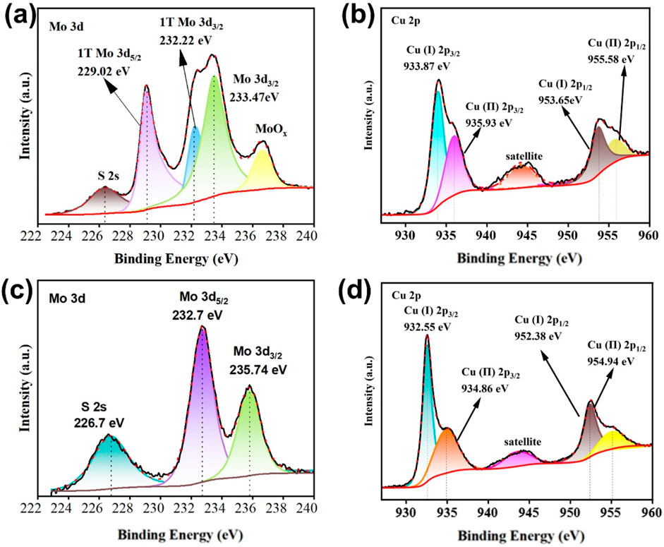
Figure 3. XPS of Cu3N, MoS2 and Cu3N/MoS2. (a) Mo 3d spectrum of MoS2. (b) Cu 2p spectrum of Cu3N. (c) Mo 3d spectrum of Cu3N/MoS2. (d) Cu 2p spectrum of Cu3N/MoS2.
HER activity was evaluated in 0.5 M H2SO4 (pH ≈ 0.34) using a standard three-electrode configuration (Ag/AgCl reference, graphite counter). All potentials were converted to the RHE scale according to E(RHE) = E(Ag/AgCl) + 0.0592 pH + 0.197, and iR-drop was corrected by 90% unless otherwise noted. Polarization curves (LSV) and Tafel plots for pristine Cu3N, pristine MoS2 and Cu3N/MoS2 with feed ratios of 1:0.5, 1:1 and 1:2 are shown in Figure 4.
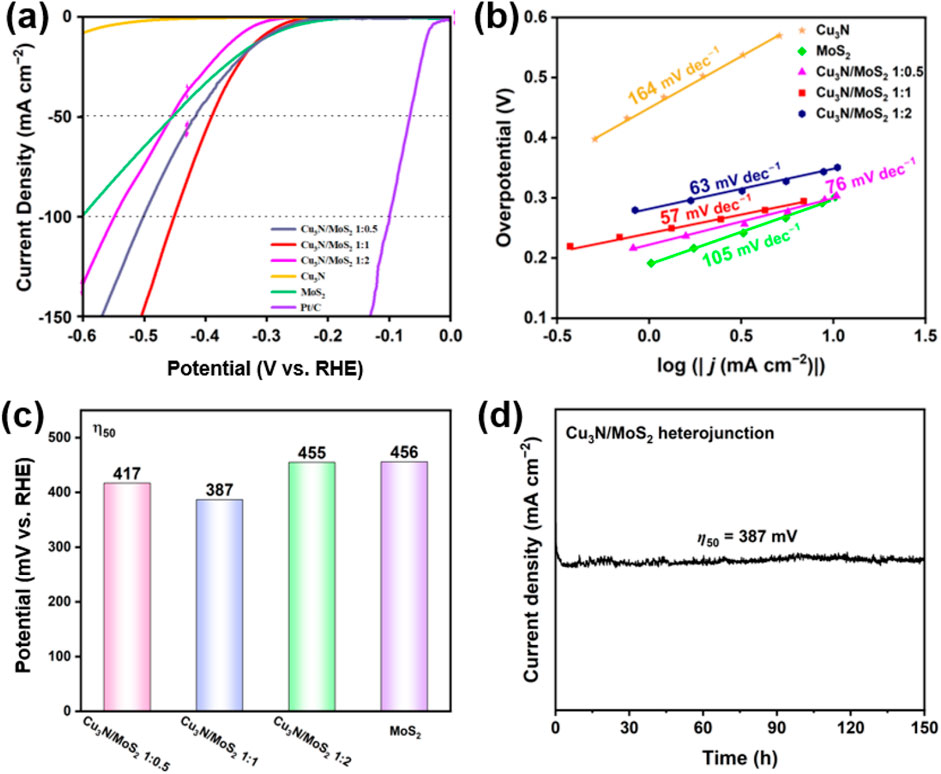
Figure 4. (a) LSV curves of Cu3N, MoS2 and Cu3N/MoS2 with different feed ratios. (b) Tafel slope of Cu3N, MoS2 and Cu3N/MoS2 with different feed ratios. (c) Overpotential of MoS2 and Cu3N/MoS2 with different feed ratios at 50 mA cm−2 of current density. (d) Chronopotentiometry at 387 mV overpotential for 150 h.
The overpotential required to deliver j = 50 mA cm−2 (η50) and the Tafel slope extracted from the low-overpotential region are summarized in Figure 4. Consistent with the LSV traces (Figure 4a), the Cu3N/MoS2 (1:1) heterostructure exhibits the lowest η50 (387 mV), outperforming pristine MoS2 (≈456 mV) and far exceeding Cu3N, which shows negligible activity at this current density (Figures 4a,c). Increasing or decreasing the MoS2 fraction from the 1:1 optimum degrades performance (η50 = 417–455 mV) (Figure 4c), indicating that an appropriate Cu3N-MoS2 balance is crucial for maximizing accessible active sites and charge-transfer pathways. Long-term stability was assessed via chronopotentiometry at 387 mV of overpotential over 150 h (Figure 4d). The Cu3N/MoS2(1:1) electrode shows negligible performance decay, demonstrating excellent durability in acidic conditions.
In acidic media, canonical slopes of ≈120, ≈40 and ≈30 mV dec−1 are typically associated with Volmer (H* adsorption), Heyrovsky (electrochemical desorption) and Tafel rate-determining steps, respectively (Jacobson et al., 2022). The value of 57 mV dec−1 for the 1:1 sample points to a Volmer–Heyrovsky mechanism, whereas pristine MoS2 (105 mV dec−1) is largely limited by the Volmer adsorption step (Figure 4b). The substantial reduction in Tafel slope for the 1:1 heterostructure signifies faster interfacial charge transfer and more favorable H* adsorption free energy (ΔGH*), in line with the electronic modulation inferred from XPS (electron flow from Cu3N to MoS2) and the coherent/strained interfaces resolved by XRD/TEM.
Electrochemical impedance spectroscopy (EIS) was carried out for Cu3N, MoS2, and Cu3N/MoS2 with varied ratios (Figure 5a). The Nyquist plots deviate from an ideal semicircle, likely due to the porous electrode, heterogeneous interfaces, and mixed kinetics-diffusion contributions (rather than a simple Randles circuit). Even so, the high-frequency intercepts and arc radii remain diagnostic of charge transfer. The Cu3N/MoS2 (1:1) sample shows the smallest arc radius, indicating the lowest Rct, which agrees with its lower overpotential, smaller Tafel slope, and superior durability. These results confirm that the 1:1 heterojunction affords the most effective interfacial coupling and fastest charge transport among the tested catalysts (Feng et al., 2022).
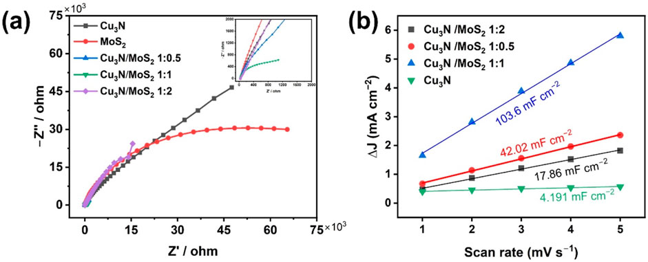
Figure 5. (a) EIS of Cu3N, MoS2 and Cu3N/MoS2 with different feed ratios. (b) Cdl of Cu3N and Cu3N/MoS2 with different feed ratios.
The electrochemically active surface area (ECSA) was estimated from the double-layer capacitance (Cdl) obtained by cyclic voltammetry in a non-Faradaic potential window at various scan rates. The slope of the capacitive current density (Δj) versus scan rate plot yields Cdl values (Figure 5b). The Cdl of Cu3N/MoS2(1:1) is ∼25× larger than that of pristine Cu3N and markedly higher than those of the other composites, signifying a dramatic increase in accessible active sites. This enhancement originates from the hierarchical core–shell morphology and ultrathin MoS2 nanosheets observed in SEM/TEM, which expose abundant edge sites while preserving open ion-transport channels. To further evaluate the intrinsic catalytic activity, LSV curves normalized to the electrochemical surface area (ECSA) were recorded (Supplementary Figure S6). The ECSA-normalized activity sequence follows Cu3N/MoS2(1:1) < Cu3N/MoS2(1:0.5) < Cu3N/MoS2 (1:2) (under 0.1 mA cm−2), indicating that the 1:2 composite delivers the highest intrinsic activity per active site. However, the conventional LSV (Figure 4a) shows the order Cu3N/MoS2(1:2) < Cu3N/MoS2(1:0.5) < Cu3N/MoS2(1:1) (under 50 mA cm−2), demonstrating that the 1:1 composite exhibits the best overall apparent performance. This difference arises because ECSA normalization highlights intrinsic activity per site, whereas the conventional curves reflect both site activity and the density of accessible active sites. Thus, although Cu3N/MoS2(1:2) features highly active sites, its relatively limited surface area reduces the overall current density. In contrast, Cu3N/MoS2(1:1) achieves an optimal balance between intrinsic activity and accessible sites, leading to the best overall HER performance. These findings confirm that the synergistic p–n interfacial coupling not only enhances site activity but also optimizes charge transport and site accessibility, together underpinning the superior HER performance of Cu3N/1T-MoS2.
The EIS and Cdl results together demonstrate that the superior HER activity of Cu3N/MoS2(1:1) stems from a dual benefit: (i) enhanced interfacial charge transfer, facilitated by strong electronic coupling and lattice-matched interfaces between Cu3N and MoS2; and (ii) maximised ECSA, arising from the optimal MoS2 coverage that prevents both under-exposure of catalytic edges (as in low-Mo samples) and blockage of conductive pathways (as in high-Mo samples). These synergistic effects explain why the 1:1 heterostructure achieves the best performance metrics across all electrochemical analyses.
The band-edge positions of p-type Cu3N and n-type MoS2 were determined by combining diffuse reflectance spectroscopy (DRS), Mott–Schottky (M–S) analysis, and valence band (VB) XPS measurements, enabling precise construction of their energy level diagrams relative to RHE.
From the Tauc plots (Figures 6a,b), the optical band gaps (Eg) were extracted as 1.12 eV for MoS2 and 1.34 eV for Cu3N (Feng et al., 2015; Makuła et al., 2018). Mott–Schottky plots (Figures 6c,d) recorded at different frequencies exhibit opposite slopes, confirming the p-type semiconductor of Cu3N and the n-type semiconductor of MoS2 (Gelderman et al., 2007; Sivula, 2021; Xu et al., 2022). The flat-band potentials (Efb) were determined to be +1.59 V (vs. RHE) for Cu3N and +0.116 V (vs. RHE) for MoS2. For p-type Cu3N, the VB maximum (VBM) lies slightly below Efb (≈0.2 eV), giving EVB ≈ +1.79 V vs. RHE. For n-type MoS2, Efb approximates the conduction band minimum (CBM), thus ECB ≈ −0.08 V (vs. RHE). According to ECB = EVB − E.g., the ECB of Cu3N and EVB of MoS2 are 0.45 V and 1.04 V (vs. RHE), respectively.
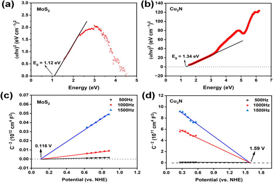
Figure 6. Tauc plots of (a) MoS2 and (b) Cu3N. Mott-Schottky plots of (c) MoS2 and (d) Cu3N at different frequency.
On the basis of the foregoing analysis, a plausible catalytic mechanism was elucidated. The Cu3N/MoS2 heterojunction was constructed via intimate contact between Cu3N nanostructures and layered MoS2, forming a p-n charge transfer pathway (Scheme 1). (Dai et al., 2024; Li and Zhou, 2021; Li et al., 2025; Qin et al., 2023; Zhu et al., 2020a; Zhu et al., 2020b) Upon contact, the difference in Fermi levels drives electrons from MoS2 to Cu3N, resulting in electron accumulation on the Cu3N side and hole accumulation on the MoS2 side. This interfacial charge redistribution generates a built-in electric field across the junction, inducing upward bending of MoS2 bands and downward bending of Cu3N bands until thermodynamic equilibrium is reached. Such an internal field has been widely recognized to facilitate charge separation and directional migration in heterojunction electrocatalysts.
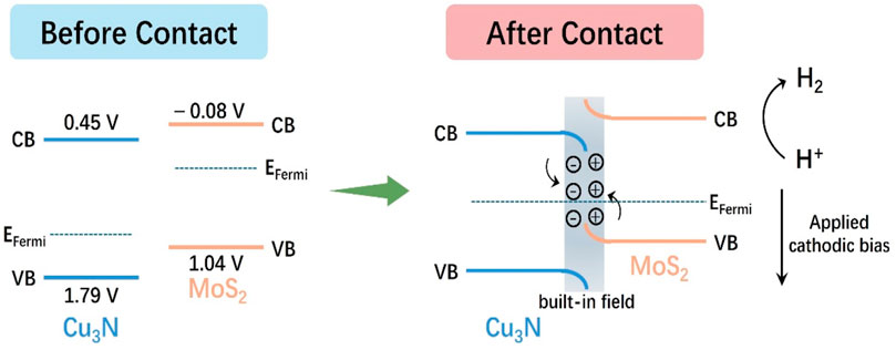
Scheme 1. The mechanism of Cu3N/MoS2 of electrocatalytic hydrogen evolution.
Under cathodic polarization, electrons are preferentially injected into the MoS2 conduction band, where they participate in the Volmer step (H+ + e− → H*) on exposed S-edge/Mo-center sites, followed by either the Heyrovsky (H* + H+ + e− → H2) or Tafel (2H* → H2) step. Simultaneously, bias-driven holes are directed towards Cu3N and consumed via the external circuit, effectively suppressing charge recombination. The synergistic action of the internal field and external bias thus ensures spatial separation of electrons (localized in MoS2-CB) and holes (localized in Cu3N-VB).
Electrochemical impedance spectroscopy (EIS) measurements demonstrate that the Cu3N/MoS2 electrode exhibits a markedly reduced charge-transfer resistance (Rct) compared to pristine components, while double-layer capacitance (Cdl) measurements reveal an increased electrochemically active surface area (ECSA). These results confirm accelerated charge transport and higher active site density, consistent with the lower Tafel slope and higher turnover frequency observed. The hierarchical architecture further facilitates electrolyte penetration and rapid release of evolved H2, maintaining high catalytic activity and stability under large current densities.
The Cu3N/1 T-MoS2 heterojunction delivers a balanced acidic-HER performance, combining a low overpotential at practical current density (η50 = 387 mV; Tafel = 57 mV dec−1), 150 h durability, and robust operation in 0.5 M H2SO4 (comparison Supplementary Table S1). This co-optimization stems from a p–n built-in field that drives directional charge separation, noble-metal-free electronic wiring from Cu3N, and interfacial stabilization of the 1 T phase. The straightforward synthesis and interfacial durability further support scale-up and device integration.
4 Conclusion
In conclusion, we have developed an interface-engineered Cu3N/1 T-MoS2 heterojunction that couples conductive p-type Cu3N nanocubes with ultrathin MoS2 nanosheets. The composite achieves 387 mV at 50 mA cm-2 with a 57 mV dec−1 Tafel slope in 0.5 M H2SO4 and maintains performance for 150 h. Structure–property correlation shows: (i) coherent interfaces and interfacial strain verified by XRD/TEM; (ii) XPS-evidenced charge redistribution; (iii) lowest Rct and highest Cdl (up to 103.6 mF cm-2) among all samples, indicating rapid charge transport and abundant active sites. The activity enhancement is thus attributed to a p–n heterojunction with a built-in electric field, which funnels electrons toward MoS2 edge sites while suppressing recombination. This study positions Cu3N as a versatile platform for stabilizing conductive MoS2 and offers generalizable design guidelines for interfacial-coupled HER electrocatalysts operating in acidic media.
Data availability statement
The original contributions presented in the study are included in the article/Supplementary Material, further inquiries can be directed to the corresponding authors.
Author contributions
TH: Validation, Methodology, Investigation, Writing – original draft. WX: Conceptualization, Investigation, Supervision, Funding acquisition, Writing – review and editing, Project administration, Data curation, Methodology, Validation. FJ: Writing – review and editing. VP: Writing – review and editing. QZ: Writing – review and editing, Methodology, Formal analysis. SK: Writing – review and editing, Methodology, Formal analysis. AY: Writing – review and editing.
Funding
The author(s) declare that financial support was received for the research and/or publication of this article. This work was financially supported by the Natural Science Foundation of Hunan Province (No.2024JJ7407), Outstanding Youth Foundation of Hunan Provincial Education Department (No.23B0503), Scientific research start-up funding of Jishou university, which were greatly appreciated.
Conflict of interest
The authors declare that the research was conducted in the absence of any commercial or financial relationships that could be construed as a potential conflict of interest.
Generative AI statement
The author(s) declare that no Generative AI was used in the creation of this manuscript.
Any alternative text (alt text) provided alongside figures in this article has been generated by Frontiers with the support of artificial intelligence and reasonable efforts have been made to ensure accuracy, including review by the authors wherever possible. If you identify any issues, please contact us.
Publisher’s note
All claims expressed in this article are solely those of the authors and do not necessarily represent those of their affiliated organizations, or those of the publisher, the editors and the reviewers. Any product that may be evaluated in this article, or claim that may be made by its manufacturer, is not guaranteed or endorsed by the publisher.
Supplementary material
The Supplementary Material for this article can be found online at: https://www.frontiersin.org/articles/10.3389/fenrg.2025.1683318/full#supplementary-material
Footnotes
1For Original Research articles, please note that the Material and Methods section can be placed in any of the following ways: before Results, before Discussion or after Discussion
References
Amiinu, I. S., Pu, Z., Liu, X., Owusu, K. A., Monestel, H. G. R., Boakye, F. O., et al. (2017). Multifunctional Mo–N/C@MoS2 electrocatalysts for HER, OER, ORR, and Zn–Air batteries. Adv. Funct. Mater. 27 (44), 1702300. doi:10.1002/adfm.201702300
Ayodele, B. V., Mustapa, S. I., Abdullah, T. A. R. B. T., and Salleh, S. F. S. F. (2019). A mini-review on hydrogen-rich syngas production by thermo-catalytic and bioconversion of biomass and its environmental implications. Front. Energy Res. 7, 118. doi:10.3389/fenrg.2019.00118
Boretti, A., Nayfeh, J., and Al-Maaitah, A. (2021). Hydrogen production by solar thermochemical water-splitting cycle via a beam down concentrator. Front. Energy Res. 9, 666191. doi:10.3389/fenrg.2021.666191
Chia, X., Eng, A. Y. S., Ambrosi, A., Tan, S. M., and Pumera, M. (2015). Electrochemistry of nanostructured layered transition-metal dichalcogenides. Chem. Rev. 115 (21), 11941–11966. doi:10.1021/acs.chemrev.5b00287
Chiu, N. C., Lessard, J. M., Musa, E. N., Lancaster, L. S., Wheeler, C., Krueger, T. D., et al. (2024). Elucidation of the role of metals in the adsorption and photodegradation of herbicides by metal-organic frameworks. Nat. Commun. 15, 1459. doi:10.1038/s41467-024-45546-y
Dai, M., Zhang, T., Huang, J., Lang, X., Li, Q., Zou, J., et al. (2024). Construction of a pp heterojunction Co3O4/MoS2 electrocatalyst for boosting hydrogen evolution reaction. Electrochimica Acta 494, 144451. doi:10.1016/j.electacta.2024.144451
Du, L., Xiong, H., Lu, H., Yang, L. M., Liao, R. Z., Xia, B. Y., et al. (2022). Electroshock synthesis of a bifunctional nonprecious multi-element alloy for alkaline hydrogen oxidation and evolution. Pap. Present. A. T. Explor. 2, 20220024. doi:10.1002/exp.20220024
Feng, Y., Lin, S., Huang, S., Shrestha, S., and Conibeer, G. (2015). Can tauc plot extrapolation be used for direct-band-gap semiconductor nanocrystals? J. Appl. Phys. 117 (12), 125701. doi:10.1063/1.4916090
Feng, Y., Guan, Y., Zhou, E., Zhang, X., and Wang, Y. (2022). Nanoscale double-heterojunctional electrocatalyst for hydrogen evolution. Adv. Sci. 9 (18), 2201339. doi:10.1002/advs.202201339
Gan, L., Lai, J., Liu, Z., Luo, J., Zhang, S., and Zhang, Q. (2022). Interfacial engineering of heterojunction copper-cobalt-nickel nitride as binder-free electrode for efficient water splitting. J. Alloys Compd. 905, 164200. doi:10.1016/j.jallcom.2022.164200
Gelderman, K., Lee, L., and Donne, S. W. (2007). Flat-band potential of a semiconductor: using the mott–schottky equation. J. Chem. Educ. 84 (4), 685. doi:10.1021/ed084p685
Gong, F., Liu, Y., Zhao, Y., Liu, W., Zeng, G., Wang, G., et al. (2023). Universal sub-nanoreactor strategy for synthesis of yolk-shell MoS2 supported single atom electrocatalysts toward robust hydrogen evolution reaction. Angew. Chem. Int. Ed. 62 (40), e202308091. doi:10.1002/ange.202308091
Jacobson, M. Z., Krauland, A.-K. v., Coughlin, S. J., Dukas, E., Nelson, A. J. H., Palmer, F. C., et al. (2022). Low-cost solutions to global warming, air pollution, and energy insecurity for 145 countries. Energy and Environ. Sci. 15 (8), 3343–3359. doi:10.1039/d2ee00722c
Jayabal, S., Wu, J., Chen, J., Geng, D., and Meng, X. (2018). Metallic 1T-MoS2 nanosheets and their composite materials: preparation, properties and emerging applications. Mater. Energy 10, 264–279. doi:10.1016/j.mtener.2018.10.009
Jiang, X., Wu, K., Shao, L., Shui, M., Lin, X., Lao, M., et al. (2014). Lithium storage mechanism in superior high capacity copper nitrate hydrate anode material. J. Power Sources 260, 218–224. doi:10.1016/j.jpowsour.2014.03.021
Jin, H., Zhang, Y., Cao, Z., Liu, J., and Ye, S. (2025). Atomically dispersed Sn on core-shell MoS2 nanoreactors as mott-schottky phase junctions for efficient electrocatalytic hydrogen evolution. Adv. Mater. 37 (33), 2502977. doi:10.1002/adma.202502977
Kwon, H. R., Yang, J. W., and Jang, H. W. (2025). Metal nitride catalysts for photoelectrochemical and electrochemical catalysis. Pap. Present. Explor. 5, 20240013. doi:10.1002/exp.20240013
Li, J., and Zhou, X. (2021). First principles calculations of electrical and optical properties of Cu3N/MoS2 heterostructure with tunable bandgaps. Appl. Phys. A 127, 693. doi:10.1007/s00339-021-04858-2
Li, X., Hao, X., Abudula, A., and Guan, G. (2016). Nanostructured catalysts for electrochemical water splitting: current state and prospects. J. Mater. Chem. A 4 (31), 11973–12000. doi:10.1039/c6ta02334g
Li, L., Wang, P., Shao, Q., and Huang, X. (2020). Metallic nanostructures with low dimensionality for electrochemical water splitting. Chem. Soc. Rev. 49 (10), 3072–3106. doi:10.1039/d0cs00013b
Li, X., Guan, H., and Mu, Z. (2025). DFT study of a promising water splitting photocatalyst: Cu3N/MoS2 heterojunction. J. Electron. Mater. 54, 2921–2929. doi:10.1007/s11664-025-11769-y
Liu, Y., Jiang, S., Li, S., Zhou, L., Li, Z., Li, J., et al. (2019). Interface engineering of (Ni, Fe)S2@MoS2 heterostructures for synergetic electrochemical water splitting. Appl. Catal. B Environ. 247, 107–114. doi:10.1016/j.apcatb.2019.01.094
Liu, S., Zhou, L., Zhang, W., Jin, J., Mu, X., Zhang, S., et al. (2020). Stabilizing sulfur vacancy defects by performing “click” chemistry of ultrafine palladium to trigger a high-efficiency hydrogen evolution of MoS2. Nanoscale 12 (18), 9943–9949. doi:10.1039/D0NR01693D
Makuła, P., Pacia, M., and Macyk, W. (2018). How to correctly determine the band gap energy of modified semiconductor photocatalysts based on UV–Vis spectra. J. Phys. Chem. Lett. 9 (23), 6814–6817. doi:10.1021/acs.jpclett.8b02892
Mallick, B., Rajak, A., Giri, S., Behera, L., Parija, B., Mallick, P., et al. (2024). A new technique for synthesis of the Cu3N and its structural indexing. Indian J. Phys. 98, 4039–4051. doi:10.1007/s12648-024-03178-4
McHugh, P. J., Stergiou, A. D., and Symes, M. D. (2020). Decoupled electrochemical water splitting: from fundamentals to applications. Adv. Energy Mater. 10 (44), 2002453. doi:10.1002/aenm.202002453
Meshesha, M. M., Gautam, J., Chanda, D., Jang, S. G., and Yang, B. L. (2023). Enhancing the electrochemical activity of zinc cobalt sulfide via heterojunction with MoS2 metal phase for overall water splitting. J. Colloid Interface Sci. 652, 272–284. doi:10.1016/j.jcis.2023.08.005
Miao, L., Jia, W., Cao, X., and Jiao, L. (2024). Computational chemistry for water-splitting electrocatalysis. Chem. Soc. Rev. 53 (6), 2771–2807. doi:10.1039/D2CS01068B
Mondal, S., and Raj, C. R. (2018). Copper nitride nanostructure for the electrocatalytic reduction of oxygen: kinetics and reaction pathway. J. Phys. Chem. C 122 (32), 18468–18475. doi:10.1021/acs.jpcc.8b03840
Qin, M., Chen, L., Zhang, H., Humayun, M., Fu, Y., Xu, X., et al. (2023). Achieving highly efficient pH-universal hydrogen evolution by Mott-Schottky heterojunction of Co2P/Co4N. Chem. Eng. J. 454, 140230. doi:10.1016/j.cej.2022.140230
Rao, T., Wang, H., Zeng, Y.-J., Guo, Z., Zhang, H., and Liao, W. (2021). Phase transitions and water splitting applications of 2D transition metal dichalcogenides and metal phosphorous trichalcogenides. Adv. Sci. 8 (10), 2002284. doi:10.1002/advs.202002284
Sivula, K. (2021). Mott-Schottky analysis of photoelectrodes: sanity checks are needed. ACS Energy Lett. 6 (7), 2549–2551. doi:10.1021/acsenergylett.1c01245
Sun, H., Xu, X., Kim, H., Jung, W., Zhou, W., and Shao, Z. (2023). Electrochemical water splitting: bridging the gaps between fundamental research and industrial applications. Energy and Environ. Mater. 6 (5), e12441. doi:10.1002/eem2.12441
Sun, H., Xu, X., Song, Y., Zhou, W., and Shao, Z. (2021). Designing high-valence metal sites for electrochemical water splitting. Adv. Funct. Mater. 31 (16), 2009779. doi:10.1002/adfm.202009779
Sun, Y., Xu, S., Ortíz-Ledón, C. A., Zhu, J., Chen, S., and Duan, J. (2021). Biomimetic assembly to superplastic metal–organic framework aerogels for hydrogen evolution from seawater electrolysis. Pap. Present. A. T. Explor. 1, 20210021. doi:10.1002/exp.20210021
Vasiliadou, I. A., Berná, A., Manchon, C., Melero, J. A., Martinez, F., Esteve-Nuñez, A., et al. (2018). Biological and bioelectrochemical systems for hydrogen production and carbon fixation using purple phototrophic bacteria. Front. Energy Res. 6, 107. doi:10.3389/fenrg.2018.00107
Wang, J., Fang, W., Hu, Y., Zhang, Y., Dang, J., Wu, Y., et al. (2020). Different phases of few-layer MoS2 and their silver/gold nanocomposites for efficient hydrogen evolution reaction. Catal. Sci. and Technol. 10 (1), 154–163. doi:10.1039/c9cy02158b
Wang, J., Liu, Z., Dai, Z., Song, X., and Liu, X. (2023). Multifunctional catalytic activity of Cu3N (001) surface: a first-principles study. ChemPhysMater 2 (3), 231–238. doi:10.1016/j.chphma.2022.10.001
Wang, L., Zhang, C., Cao, Z., Zeng, G., Liu, J., and Ye, S. (2024). Dual modulation of bulk electronic structure and surficial active sites in sea urchin-like MoO2 nanoreactors promoting electrocatalytic hydrogen evolution. Adv. Funct. Mater. 34 (42), 2406670. doi:10.1002/adfm.202406670
Xu, D., Zhang, S.-N., Chen, J.-S., and Li, X.-H. (2022). Design of the synergistic rectifying interfaces in Mott-Schottky catalysts. Chem. Rev. 123 (1), 1–30. doi:10.1021/acs.chemrev.2c00426
Xue, H., Meng, A., Chen, C., Xue, H., Li, Z., and Wang, C. (2022). Phosphorus-doped MoS2 with sulfur vacancy defects for enhanced electrochemical water splitting. Sci. China Mater. 65, 712–720. doi:10.1007/s40843-021-1774-9
Yu, Y., Nam, G. H., He, Q., Wu, X.-J., Zhang, K., Yang, Z., et al. (2018). High phase-purity 1T′-MoS2- and 1T′-MoSe2-layered crystals. Nat. Chem. 10, 638–643. doi:10.1038/s41557-018-0035-6
Zhang, K., Ai, Z., Huang, M., Shi, D., Shao, Y., Hao, X., et al. (2021). Type II cuprous oxide/graphitic carbon nitride p-n heterojunctions for enhanced photocatalytic nitrogen fixation. J. Catal. 395, 273–281. doi:10.1016/j.jcat.2021.01.013
Zhu, L., Cao, X., Gong, C., Jiang, A., Cheng, Y., and Xiao, J. (2020a). Preparation of Cu3N/MoS2 heterojunction through magnetron sputtering and investigation of its structure and optical performance. Materials 13 (8), 1873. doi:10.3390/ma13081873
Keywords: Cu3N, 1T-MoS2, p–n heterojunction, electrocatalytic hydrogen evolution, interfacial engineering
Citation: Huang T, Xia W, Joshua F, Ponnusamy VS, Zhang Q, Kumar S and Yu A (2025) Interfacial p–n coupling in Cu3N/1T-MoS2 heterojunctions drives efficient and durable acidic hydrogen evolution. Front. Energy Res. 13:1683318. doi: 10.3389/fenrg.2025.1683318
Received: 10 August 2025; Accepted: 13 October 2025;
Published: 27 October 2025.
Edited by:
Geeta Durga, Sharda University, IndiaCopyright © 2025 Huang, Xia, Joshua, Ponnusamy, Zhang, Kumar and Yu. This is an open-access article distributed under the terms of the Creative Commons Attribution License (CC BY). The use, distribution or reproduction in other forums is permitted, provided the original author(s) and the copyright owner(s) are credited and that the original publication in this journal is cited, in accordance with accepted academic practice. No use, distribution or reproduction is permitted which does not comply with these terms.
*Correspondence: Wu Xia, Y2hlbXh3XzIwMDhAMTYzLmNvbQ==; Ao Yu, YW8ueXVAdWNmLmVkdQ==