 F. Di Martino1,2,3
 D. Del Sarto2,3,4*
 G. Bass5
 S. Capaccioli2,6M. Celentano2,3
 D. Coves7A. Douralis5M. Marinelli8
 M. Marrale9,10,11L. Masturzo2,12
 G. Milluzzo11M. Montefiori3,6
 F. Paiar2,13
 J. H. Pensavalle2,12
 L. Raffaele14
 F. Romano11
 A. Subiel5
 E. Touzain7G. Verona Rinati8
 G. Felici12
- 1Azienda Ospedaliero Universitaria Pisana, Pisa, Italy
- 2Centro Pisano Multidisciplinare Sulla Ricerca e Implementazione Clinica Della Flash Radiotherapy (CPFR@CISUP), Pisa, Italy
- 3National Institute of Nuclear Physics (INFN), Section of Pisa, Pisa, Italy
- 4Center for Instrument Sharing of the University of Pisa (CISUP), University of Pisa, Pisa, Italy
- 5National Physical Laboratory, Medical Radiation Science, Teddington, United Kingdom
- 6Department of Physics, University of Pisa, Pisa, Italy
- 7Bergoz Instrumentation, Saint-GenisPouilly, France
- 8Department of Industrial Engineering, University of Rome “Tor Vergata”, Rome, Italy
- 9Department of Physics and Chemistry “Emilio Segrè” (DIFC), University of Palermo, Palermo, Italy
- 10Advanced Technologies Network (ATeN) Center, University of Palermo, Palermo, Italy
- 11National Institute of Nuclear Physics (INFN), Section of Catania, Catania, Italy
- 12SIT Sordina IORT Technologies, Aprilia (LT), Italy
- 13Azienda Ospedaliero Universitaria Pisana, U. O. Radioterapia Universitaria, Pisa, Italy
- 14National Institute of Nuclear Physics (INFN), Laboratori Nazionali Del SUD (LNS), Catania, Italy
The FLASH effect is a radiobiological phenomenon that has garnered considerable interest in the clinical field. Pre-clinical experimental studies have highlighted its potential to reduce side effects on healthy tissues while maintaining isoeffectiveness on tumor tissues, thus widening the therapeutic window and enhancing the effectiveness of radiotherapy. The FLASH effect is achieved through the administration of the complete therapeutic radiation dose within a brief time frame, shorter than 200 milliseconds, and, therefore, utilizing remarkably high average dose rates above at least 40 Gy/s. Despite its potential in radiotherapy, the radiobiological mechanisms governing this effect and its quantitative relationship with temporal parameters of the radiation beam, such as dose-rate, dose-per-pulse, and average dose-rate within the pulse, remain inadequately elucidated. A more profound comprehension of these underlying mechanisms is imperative to optimize the clinical application and translation of the FLASH effect into routine practice. Due to the aforementioned factors, the undertaking of quantitative radiobiological investigations becomes imperative, necessitating the utilization of sophisticated and adaptable apparatus capable of generating radiation beams with exceedingly high dose-rates and dose-per-pulse characteristics. This study presents a comprehensive account of the design and operational capabilities of a Linear Accelerator (LINAC) explicitly tailored for FLASH radiotherapy research purposes. Termed the “ElectronFlash” (EF) LINAC, this specialized system employs a low-energy configuration (7 and 9 MeV) and incorporates a triode gun. The EF LINAC is currently operational at the Centro Pisano FLASH Radiotherapy (CPFR) facility located in Pisa, Italy. Lastly, this study presents specific instances exemplifying the LINAC’s adaptability, enabling the execution of hitherto unprecedented experiments. By enabling independent variations of the temporal parameters of the radiation beam implicated in the FLASH effect, these experiments facilitate the acquisition of quantitative data concerning the effect’s dependence on these specific parameters. This novel approach hopefully contributes to a more comprehensive understanding of the FLASH effect, shedding light on its intricate radiobiological behavior and offering valuable insights for optimizing its clinical implementation.
1 Introduction
FLASH Radiotherapy (FLASH-RT) is a promising radiotherapy technique that involves delivering the entire radiation dose at an extremely high dose rate, much higher than conventional methods. The technique has been tested in various preclinical experiments using different animals and organs, and results have shown a significant reduction in side effects on healthy tissues while preserving its therapeutic efficacy on tumor tissue. This has generated considerable excitement in the radiotherapy community as FLASH-RT may provide a way to effectively treat tumors that are currently non efficiently treated with conventional radiotherapy [1–7]; in particular:
1. Radioresistant tumors located in close proximity to radiosensitive “serial” organs: it is hypothesized that a higher RT dose could be delivered to the tumor without inducing severe toxicities to the surrounding normal tissues as would be expected following CONV-RT.
2. Large tumors arising in “parallel” organs: the delivery of tumoricidal RT dose is hampered by the size and local extension of tumor mass that would lead to a low-dose irradiation of a significant portion of organ at risk with a subsequent unacceptable risk of severe toxicity.
3. Reirradiation: tumor recurrence often occurs within a previously irradiated high-dose region. This means that the dose required for tumor control is often much higher than that required for severe toxicity leading to an inverted relationship between NTCP and TCP curves.
Despite the very promising results, there are still many unanswered questions regarding the FLASH radiobiological mechanisms: there is still no consensus on its physical mechanism [8,9], and both its dependence on the various beam parameters and the effect on the irradiated tissues remain to be fully understood. One of the biggest challenges has been obtaining quantitative radiobiological data from in vitro/vivo experiments, which is essential to understanding the FLASH effect’s dependencies on the different beam parameters.
Currently, there are two conditions which seems to trigger the FLASH effect: average dose rate greater than 40 Gy/s and a total irradiation time less than 0.2 s [10–15]. Nevertheless, the beam temporal structure is quite complex, and these two parameters are not enough to fully describe it. An exhaustive representation of the temporal structure is reported in Figure 1:Where
− dMAX depth of maximum dose on beam axis
− Dp(n),k dose of nth pulse in the kth irradiation at DMAX [Gy]
− tpk time width of a single pulse in the kth irradiation [s]
− trk time between two pulses in the kth irradiation [s]
− PRFk Pulse Repetition Frequency in the kth irradiation [s–1]
− np,k Number of pulses of the kth irradiation
− tFLk irradiation time of the kth irradiation [s]
− tDk time separation between the end kth and the beginning of (k+1)th irradiations [s]
− TDk total delivered dose at dMAX during tFLk [Gy]
− tIRR Total irradiation time [s]
− TD total delivered dose atdDMAX during tIRR [Gy]
− ADRk Average Dose Rate during the kth irradiation at dMAX [Gy s–1]
− ADRpi,k Average Dose rate within the ith pulse during the kth irradiation at dMAX [Gy s–1]
− IDRi,k Instantaneous Dose Rate within the ith pulse during the kth irradiation at dMAX [Gy s–1]
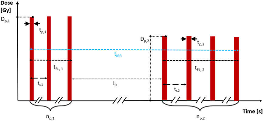
FIGURE 1. Temporal beam structure with all the relevant parameters.
In case of a single irradiation, the following relations hold:
If the irradiation consists of multiple sub-irradiations, the previous equations can be easily generalized and the additional relations hold:
with N being the total number of irradiations. It was chosen to start from the definition of dose per pulse and pulse duration (instead of introducing the dose rate directly) because these two parameters can be measured precisely and independently from each other.
Additionally, if the dose is delivered with two or more train of pulses, also the time lapse between the trains of pulses may play a relevant role. Until now, due the technological limits of the electron LINACs available, no detailed study on the impact of the different parameters is available; nevertheless, there is a large consensus about the need of such investigations, both for electrons and protons [16–22].
FLASH research until today has been substantially slowed by the absence of a specifically designed technological platform, both in terms of beam sources and in terms of beam monitoring systems and dosimeters [23–25]. More specifically, the electron accelerators adopted for FLASH radiobiological experiments are not provided with real-time monitoring of beam parameters, which makes it impossible to take output variation into account. These accelerators are typically electron accelerators designed for industrial use or modified medical accelerators, where diffuser filters and monitor chambers have been removed from the beam path [26]. This fact has somehow limited the researchers’ ability to obtain accurate and fully reproducible data on the radiobiological impact of the various beam time structure parameters potentially impacting FLASH effect.
Although the FLASH effect’s robustness has been validated by various animal models, organs, and radiobiology research works, the radiobiological mechanism underlying the effect is still unknown. While oxygen consumption has been proposed as a possible explanation [27], other works have highlighted the limits of this explanation and emphasized the need for further investigations [28]. Additionally, the dependence of the FLASH effect on the Linear Energy Transfer (LET) of the radiation used is still unknown.
A better understanding of the complexity of FLASH effect is also mandatory for the VHEE development and its clinical translation.
VHEE would allow to treat even deep-seated tumors. Different national and international research projects are aimed at the realization of Very-High-Energy-Electrons “FLASH” LINAC, with energy up to or greater than 100 MeV. However, this raises new radiobiological questions: such high energy electron beams cannot be collimated mechanically yet, like the low energy ones, but the dose to the target volume is deposited uniformly employing pencil beam scanning technique, requiring to use more fields of view to reach the desired dose conformation. It is therefore essential, before the clinical translation, to quantify any dependence of the entity of the FLASH effect on the beam volume (dimension of the beam) and on the dose fractionation, since the movement of the gantry to pass from one field of view to another is not temporally compatible with the times need to trigger the FLASH effect (<0.1–0.2 s).
In summary, while FLASH-RT has shown promising results, there are still many uncertainties and many issues that need to be addressed before it can be used in clinical practice. Further research is necessary to determine the radiobiological mechanism underlying the FLASH effect and to investigate the dependence of the effect on various beam parameters on the irradiated tissues. Advances in accelerator technology and dosimetry may provide a way to overcome the current limitations and enable researchers to obtain quantitative radiobiological data from in vitro/vivo experiments.
A specifically designed LINAC would represent a powerful tool for understanding the mechanism and exploiting the promising radiobiological findings associated with the FLASH effect. Such LINAC should provide the full capability to vary, set and monitor the whole temporal beam structure, as reported in [29]. The discussion between some of the authors of this article, led to the development of the new design of Electron Flash with a triode e-gun and its power and piloting electronics. The availability of a triode gun enables to adjust the electron fluence (and thus the dose per pulse) in a wide range maintaining the time pulse width and beam optics unchanged.
Such LINAC allows the study of the whole set of beam parameters which could impact FLASH effect: dose per pulse, pulse width, pulse repetition frequency, number of pulses, irradiation time and consequently Average and instantaneous dose rate. All these parameters can be varied independently and without altering the experimental setup, thereby minimizing experimental errors.
Thanks to special funding from Fondazione Pisa, the newly designed system has been installed in July 2022, at the Centro Pisano FLASH Radiotherapy (CPFR) in Pisa, Italy.
2 Materials and methods
2.1 Characteristics of the research LINAC system
The research LINAC described in the study is the ElectronFlash (indicated as EF in the following) produced by SIT S.p.A. (https://www.soiort.com/flash-rt-technology/[29,30]). and installed in Pisa A.O.U.P., S. Chiara Hospital.
Even though EF is a research LINAC, it has been designed in order to comply with the requirements of IEC 60601-two to one, Medical electrical equipment - Part 2–1: Particular requirements for the basic safety and essential performance of electron accelerators in the range 1 MeV–50 MeV [31]. Furthermore, as long as FLASH treatment requires even additional monitoring in order to guarantee the essential performance, novel monitoring techniques have been devised and integrated [29].
The system operates in electron mode only, with energies of 7 and 9 MeV; e-beam is collimated by means of a purely passive beam optics and several radiation fields are available (see Results section).
The accelerating waveguide is a S band standing wave accelerating guide, operating at 2.998 GHz in the π/2 mode; the electrostatic radial focusing technique is implemented, in order to avoid the use external solenoid. Such implementation guarantees the stability over time of radial beam dynamics, and therefore also beam symmetry and flatness.
The LINAC features a triode thermionic e-gun composed of an indirectly heated cathode, a control grid, and an anode. The e-gun generates an electron current in a temporal range variable from 0.2 to 4 µs with a peak accelerated current ranging from 1 up to 100 mA, which is adjustable using by means of the grid voltage. The LINAC is powered by an S-band magnetron (model MG6090 produced by E2V) delivering up to 3.1 MW. It is powered by a Solid-State Modulator (model M100 produced by Scandinova).
Beam collimation is achieved through a purely passive scattering system, and the beam is conformed into different fields thanks to different applicators, ranging from diameter 1 cm up to 12 cm.
EF is equipped with a real “dose monitoring system”, as defined in IEC 60601-2-1, § 201.3.212 [31]: “system of devices for the measurement and display of a radiation quantity directly related to the absorbed dose”.
The dose monitoring system comprises several components, each fulfilling a crucial role in signal processing. The initial stage involves the precise and linear measurement of beam current. This is accomplished using two independent Beam Current Transformers (referred to as ACCTs), designed and manufactured by Bergoz Instrumentation [32]. Previous research has demonstrated the effectiveness of this system in accurately estimating absorbed dose [33,34]. Although alternative devices have been explored [35], ACCTs now function as non-invasive sensors, safeguarding the integrity of the beam and ensuring consistent measurement precision and linearity in both conventional and UHDR modes.
Subsequently, the current waveform is digitized to facilitate charge calculation through integration. Lastly, this computed charge is converted into Monitor Units, normalized as desired by the final user. These Monitor Units are then displayed on the user interface and utilized for treatment control purposes.
ACCT are currently considered as an optimal solution for the beam monitoring in UHDR modality [25,29,36,37], it is however important to stress that a dose monitoring system is much more than the radiation detectors itself: it is a system at least capable of:
- transforming the measurement of the single pulse into a quantity proportional to the absorbed dose ([31] § 201.10.101.1.1.2) and properly visualizing such quantity in terms of MU ([31]§ 201.10.101.1.1.2);
- halting the irradiation when the programmed MU have been delivered ([31] § 201.10.101.1.1.5);
- halting the irradiation if anomalies occur in the monitoring process and/or a given threshold is trespassed [31] (§ 201.10.101.1.3 and [31] § 201.10.101.1.3).
Monitoring system reading can be normalized as desired by the final user. All such features have been implemented in EF. The monitoring system performances (linearity, long and short-term stability) are described in the Results section. A schematic of the beam optic, including the ACCT, is reported in Figure 2.
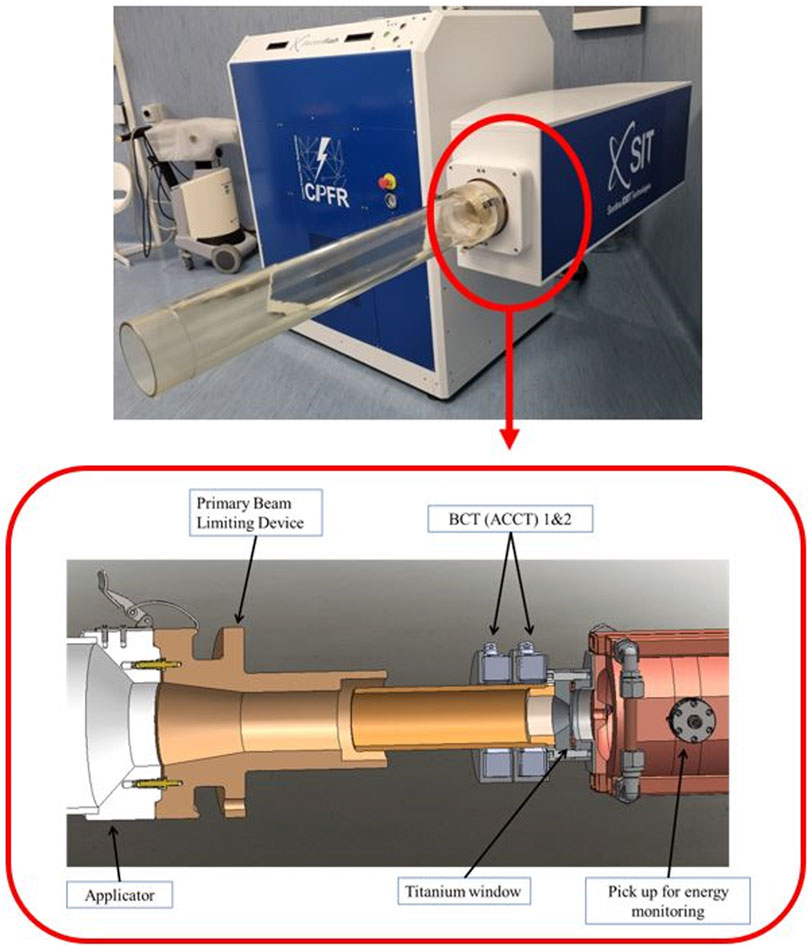
FIGURE 2. Schematic of the beam optic including ACCT.
Two screenshots reporting the monitoring system interface are presented in Figure 3. The reading of both channels for each pulse, the integral dose delivered and the temporal structure of the beam is clearly visible; in the left image an irradiation stopped by the MU limit is reported (500 MU limit set, 2 pulses lasting 4.5 µs, PRF 200 Hz, total irradiation time ≈5 m and total MU1 delivered 530) while in the right one an irradiation stopped by the number of pulses is reported (10 pulses at 200 Hz, each lasting 2.5 µs, PRF 200 Hz, total irradiation time ≈45 m).
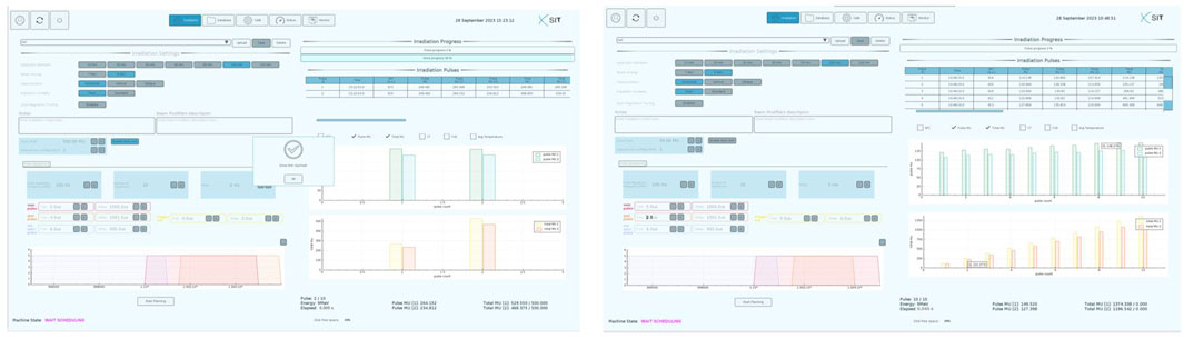
FIGURE 3. System interface of the EF LINAC.
EF can also deliver two different trains of pulses, with a time interval between the two trains in the range 0.05 s–60 s. Such feature allows the delivery of two irradiation separated by a time interval, and it is provided in order to study the possibility such dose delivery modality could enhance Flash effect.
EF is designed in a way that the user can vary independently each parameter of the beam temporal structure; notably it allows, by opportunely varying the beam current, to deliver the same dose per pulse even when varying the time width of the pulse in a large range.
The ElectronFlash can therefore adjust its average dose-per-pulse, average dose rate and its average instantaneous dose rate. This is achieved by modifying various parameters such as:
- the E-gun peak current, which leads to an accelerated current between 1 and 100 mA;
- E-gun pulse duration, which can be set between 0.2 µs and 4 µs;
- Pulse Repetition Frequency (PRF), which can be set between 1 Hz and 250 Hz with 1 Hz increments. Higher PRF are achievable, up to 400 Hz, but with a shorter radiofrequency pulse duration down to 2.5 µs instead of the standard 5 µs?
Electron beam is collimated into the target by means of PMMA cylindrical tubes, called applicators. These applicators determine the uniform field dimensions and establish an upper limit on the achievable dose per pulse by modulating the incident electron spectrum and fluence. Since the beam collimation is entirely passive, its performance remains constant over time. Consequently, real-time monitoring is not necessary for ensuring beam flatness, as the uniformity of the dose distribution at a specific depth is primarily influenced by the multiple scattering of electrons with the collimator wall.
2.2 LINAC dosimetric characterization
The dosimetric characterization of a LINAC with the illustrated characteristics pose a challenge for commercial dosimetric devices due to very high charge density generated by dose per pulse, which is three orders of magnitude greater than in conventional radiotherapy LINACs [29]. Corrective methods are not sufficient to use standard detectors for the absolute dosimetry needed for commissioning the ElectronFlash [38]. Several FLASH dedicated dosimeters are currently being developed and tested, mainly ionization chambers [22,39] and semiconductor detectors [40,41]. In this study, we used a PTW flashDiamond as the active dosimeter for both relative and absolute dosimetry. The linearity of the employed dosimeter was tested up to 18 Gy per pulse with a graphite calorimeter [42] and alanine pellets.
Additionally, we used EBT-XD Gafchromic films [43] to measure the beam profiles given their high spatial resolutions. Prior to use, we calibrated the EBT-XD films in a plastic phantom by delivering doses ranging from 0.5 to 60 Gy. The dose was delivered with a Dp of approximately 0.02 Gy, a pulse duration tp of 4 µs, and a PRF of 1 Hz. The total dose delivered was measured using an Advanced Markus ionization chamber connected to a PTW UNIDOS electrometer with a +400 V polarization. The chamber was able to correctly operate with the standard two voltage saturation correction at the polarization and dose per pulse employed. The dose values were obtained following the standard dosimetry protocol for absolute dosimetry in water TRS-398 [44], with a correction factor for the use of a plastic phantom. After a 48-h waiting period, all the films were scanned using an Epson Expression 10000XL scanner and the netOD values were converted to dose values via the calibration curves [45].
We started the dosimetric characterization by performing relative dosimetry measurements, which involved acquiring percentage depth dose (PDD) curves and lateral beam profiles. We obtained these measurements using different applicators, and also carried out measurements without any applicator, directly at the head hosing exit. The measurements were taken for both energies and three (low, mid, high) selected beam current values ((4, 60, 100 mA for 9 MeV; (15, 51, 85 mA) for 7 MeV).
To obtain the PDD curves, we measured the absorbed dose to water using the flashDiamond detector positioned in a modified MP3-XS water phantom that was adapted for horizontal irradiation by cutting a hole in one of the vertical sides and replacing it with a 1 mm thick water-tight carbon window.
The dose was delivered as train of 4µs pulses with 5 Hz PRF and evaluated moving, every 10 s, the flashDiamond detector in increments of 1 mm in the buildup region and 2 mm thereafter. Starting from the PDDs curves data, we evaluated the invariance of the R100, R90, R50 and Rp parameters (see Table 1 for definitions) for each energy, applicator, and beam current combination.
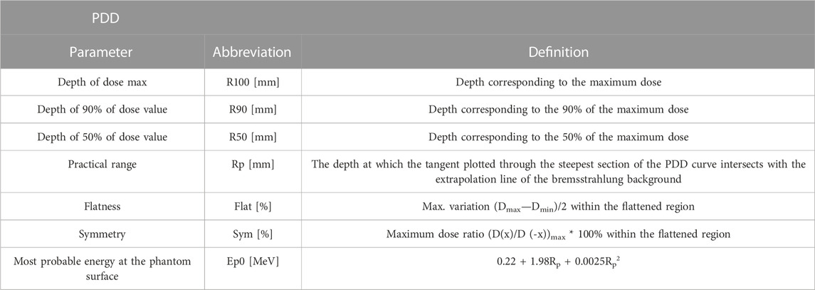
TABLE 1. Definition of parameters used to characterize the system.
To measure the beam profiles, we positioned gafchromic films between slabs of RW3 plastic phantom at a depth equivalent to the R100. The films were irradiated with the same dose, and we evaluated the beam flatness, symmetry, and the width at the 95% isodose.
For absolute dose measurements, we irradiated the flashDiamond at the dMAX depth in a water phantom using 4 µs pulses and a PRF of 5 Hz. The dose per pulse for each irradiation combination was calculated by dividing the total dose by the number of delivered pulses. To ensure sufficient statistical accuracy, we delivered a minimum of 20 pulses for the highest beam current and 200 pulses for the lowest beam current. From this data, we determined the maximum ADRp for each irradiation condition.
We then assessed the linearity of the total dose with respect to the number of pulses. This was done by delivering a different number of pulses, ranging from 1 to 60, and measuring the total dose delivered. The procedure was repeated 5 times to estimate the output variability.
Next, we evaluated the variation in LINAC output with respect to the PRF in the range of 1–245 Hz while delivering a fixed number of pulses at 9 MeV and a beam current of 60 mA. Additionally, we measured the achievable dose rate ranges by measuring the dose at PRF values of 1 Hz and 245 Hz for each beam current.
To characterize the temporal properties of the pulse, we investigated the dose dependence with respect to the pulse width for the 9 MeV beam. We measured the reproducibility of the pulse width using the signal obtained from the ACCT current transformer. This involved delivering 20 pulses and measuring the resulting pulse duration. We then varied the pulse width from approximately 4 µs–0.38 µs while recording the dose with the flashDiamond for three consecutive pulses.
3 Results
3.1 Customer Acceptance Test measurements
To evaluate the performance of the LINAC system, a set of procedures was developed in accordance with the Customer Acceptance Test (CAT). These procedures were categorized into two groups: beam properties and beam output.
For the beam properties evaluation, PDD curves were measured for both available energies (7 and 9 MeV) and for three different current values (low, medium, high) using the 40 mm diameter applicator. The PDDs were analysed to measure values such as, R100, R90, R50 and Rp as defined in Table 1. The stability of the LINAC was assessed over 3 days by checking the R50 values, which were required to be within a 1 mm tolerance using the 40 mm applicator. Furthermore, measurements of PDD were conducted using different applicators to verify the position of R50 and, consequently, the stability of PDD among the different fields. The beam profiles were also evaluated by measuring flatness symmetry and 95% isodose width for all available applicators.
Regarding the beam output, measurements were performed with both energies (7 and 9 MeV) and for 2 dose-per-pulses (high and low), setting the flashDiamond at the R100 and using the 40 mm applicator. The short-term stability of the LINAC system (i.e., the stability of charge collected in 10 consecutive irradiations) and the long-term stability (i.e., stability of the ratio between collected charge and the registered MU over a period of 3 days) were checked to be within tolerance (2% and 5%, respectively).
The proportionality between the output and the pulse duration (from 0.5 up to 4 µs) and the linearity between the output and the number of pulses were also evaluated. The linearity between the output and the registered MU was checked. This was performed with a 100 mm applicator after MU calibration (at the value 1 cGy/MU at the build-up region) for the same applicator. The proportionality ratio between the output and PRF, ranging from 5 to 245 Hz, was also checked by measuring the standard deviation of the charge collected for the same number of pulses delivered with different PRF. A summary table indicating the boundary tolerance for each measurement is provided in the Supplementary Materials.
3.2 LINAC flexibility and performance
The percentage depth dose curves obtained at 9 MeV with a fixed beam current of 4 mA for all available applicators are shown in Figure 4. The beam parameters and the maximum measured variation are listed in Table 2, with the uncollimated beam data reported separately. It is worth noting that all PDD curves, except for the uncollimated beam, exhibit a semi-flat region of approximately 10 mm for the 97% isodose, allowing for flexibility in the placement of devices or specimen. The impact of the different applicators on the PDD can be deemed relatively insignificant.
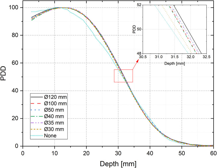
FIGURE 4. 9 MeV PDDs for various applicators.
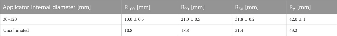
TABLE 2. PDD characteristics for the 9 MeV beam for different applicators.
Figure 5 displays the variation of the 9 MeV PDD curves in response to changes in the beam current, while Table 3 provides a summary of their characteristics: in particular it can be observed that therrent, the maximum variation observed in the R50 parameter is less than 1 mm. The differences in PDDs resulting from changes in the beam current are not critical when positioning samples at the R100, thanks to a fairly large zone of uniformity of the dose around the depth of maximum dose (dmax) observed in all three PDDs.
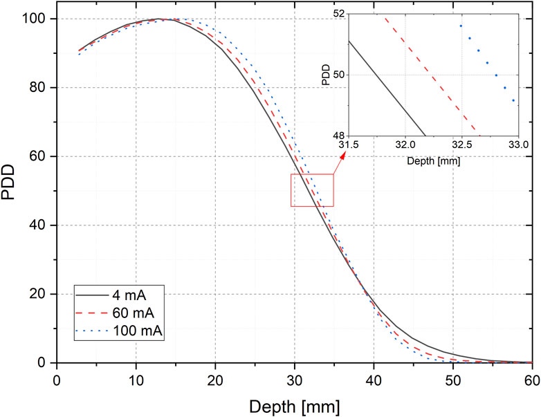
FIGURE 5. 9 MeV PDDs for different beam currents.
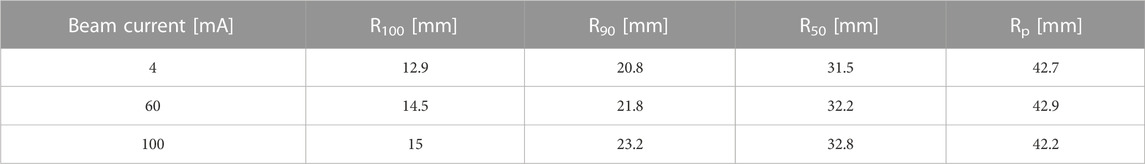
TABLE 3. PDD characteristics for the 9 MeV beam for different beam currents.
The results of the analogous studies with the 7 MeV beam are reported in the Supplementary Materials.
The beam profiles obtained at R100 with 9 MeV energy for all applicators are displayed in Figure 6, normalized to the maximum dose. Table 4 presents the corresponding Flatness, Symmetry, and the diameter of the 95% isodose for each profile. Additionally, Figure 7 depicts the gaussian profile for the uncollimated beam. Notably, the 120 mm and 100 mm applicators exhibit a sufficiently large useful field, making them suitable for accommodating various sizes of cell culture multiwell plates, thereby facilitating in vitro experiments. The smaller applicators are more suitable for irradiating individual dishes with more extreme irradiation parameters.
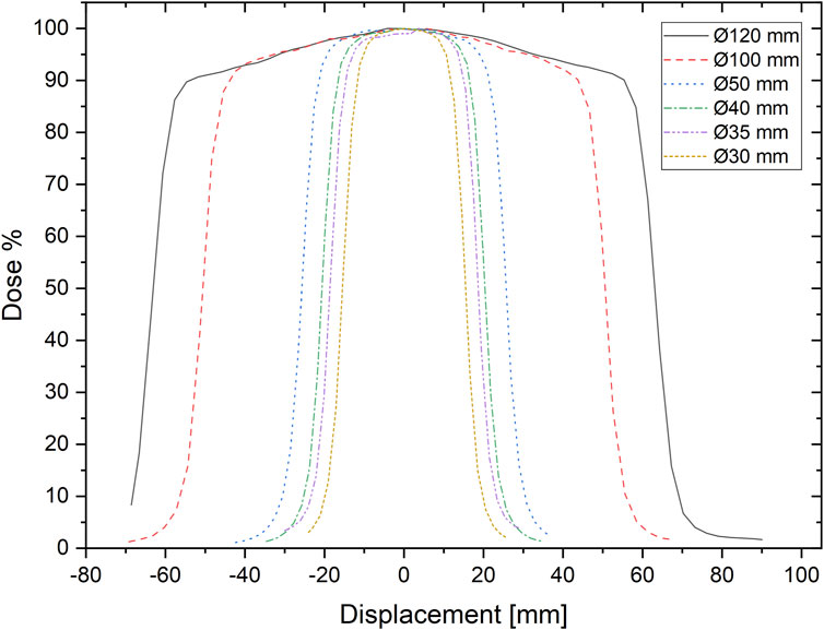
FIGURE 6. Beam profiles for all the applicators.
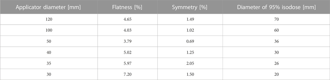
TABLE 4. Profile data for various applicators.
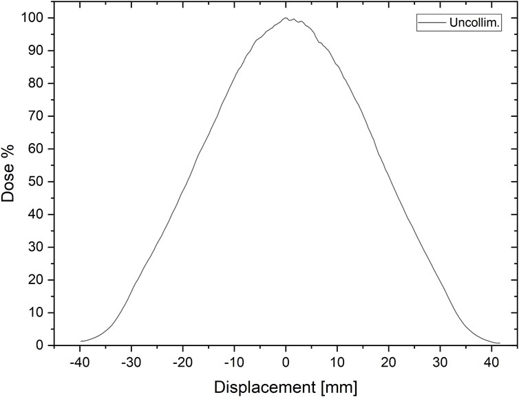
FIGURE 7. Beam profile for the uncollimated beam.
The linearity of the dose with respect to the number of delivered pulses was verified through a linear fit (y = 0.877x, R2 = 0.999). These measurements also revealed a pulse variability of less than 2%, which can be corrected by the ACCT reading.
The investigation of the LINAC output dependence on different PRF, as shown in Figure 8, resulted in a variation of less than ±1.5% relative to the average value measured when scanning various PRF. This variation was adjusted for the beam output variability monitored by the ACCT.
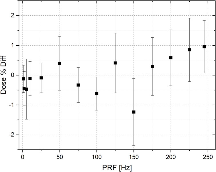
FIGURE 8. Relative differences from the mean dose value of dose measured at different PRFs.
The effect of pulse width on the dose per pulse was studied by measuring the effective pulse duration, determined as the full width at half maximum (FWHM) of the ACCT signal recorded using an oscilloscope. Figure 9 shows different pulse waveforms along with their corresponding effective durations. The measurements demonstrated high reproducibility, with relative differences of less than 0.3% observed for the same pulse duration setting. To analyze the relationship between pulse width and dose, a linear regression was performed on the dose values associated with each pulse width, as shown in Figure 10. The results revealed a clear linear trend with a slope of 0.343 and an excellent goodness of fit (R2 = 0.999).
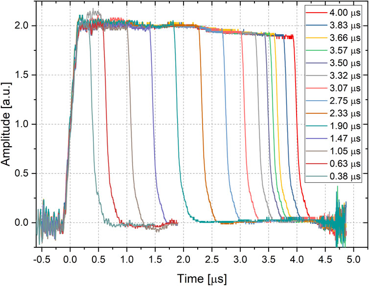
FIGURE 9. Pulse waveform for different pulse duration.
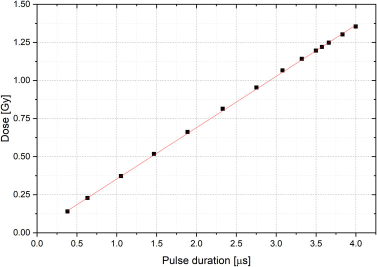
FIGURE 10. Linear fit (red) to the Dose value with respect of the pulse duration. Errorbars are on the order of graph point size.
Additionally, we calculated the ranges of irradiation parameters available at R100 for each applicator and the maximum pulse duration using the collected data. These ranges are presented in Table 5, where the available dose per pulse values at 9 MeV are explicitly listed for the 100 mm applicator, while for the other applicators, only the minimum and maximum values are provided. Intermediate values can be obtained by scaling the values of the 100 mm applicator. Furthermore, since the ADR depends on the number of pulses, even when the PRF is fixed, in the table we normalized such dependency reporting the normalized ADRn, obtained by dividing the ADR by n/(n-1), where n is the number of pulses.
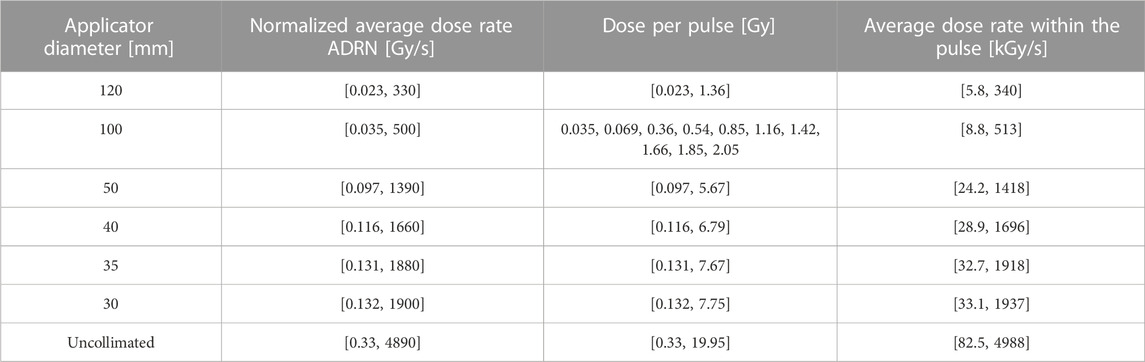
TABLE 5. Irradiation parameters available at R100. The interval extremes are reported for all but the 100 mm applicator diameter where all the available dose per pulses are listed.
3.3 Discussion
In this study, we described the unique architecture of the ElectronFlash, a triode gun electron LINAC specifically developed for investigating the FLASH effect. The dosimetric characterization of the ElectronFlash system was also described in detail. This LINAC allows independent control of three key beam parameters relevant to the FLASH effect: average dose rate, dose per pulse, and instantaneous dose rate. The flexibility to vary these parameters within a wide range, spanning from conventional radiotherapy values to extreme FLASH conditions, is a significant advantage. Importantly, these parameter changes can be achieved without modifying the experimental setup, reducing uncertainty in dosimetric and radiobiological experiments.
The ElectronFlash system is equipped with two dedicated ACCTs that enable online monitoring of output variability, allowing adjustments to account for small output variations, which have been measured to be below 2%. The availability of various applicators further enhances the versatility of the LINAC. Larger applicators enable simultaneous irradiation of multiple samples under FLASH conditions (>1 Gy per pulse) with a useful field diameter (>95%) of 70–60 mm. Smaller applicators can be used to gradually transition to extreme irradiation values at the cost of a reduced useful irradiation area. Additionally, the LINAC offers two nominal energies, 7 and 9 MeV, providing further flexibility in experimental setups.
Given the challenges of using commercial active dosimeters for FLASH irradiation, the dosimetric characterization was performed using a specially designed detector, the flashDiamond detector. The linearity of the flashDiamond detector was verified through measurements at 9 MeV using NPL’s secondary standard calorimeter and alanine pellets, traceable to UK’s primary standard electron and photon calorimeters, respectively. Calibrated EBT-XD gafchromic films were used to obtain beam profiles. The results confirmed that changes in applicators or beam current had negligible effects on the percentage depth dose (PDD) curves. Furthermore, the 9 MeV PDD curves exhibited a wide near-flat region near the maximum dose (97% isodose), allowing for flexibility in the types of specimens to be irradiated. The linearity of output with respect to the number of pulses, pulse duration, and independence on the pulse repetition frequency were also successfully verified.
Based on the dosimetric measurements, the maximum range of beam parameter excursions was determined: average dose rate ranging from ∼2 cGy/s to ∼4800 Gy/s, dose per pulse ranging from ∼2 cGy to ∼20 Gy, and average dose rate within the pulse ranging from ∼5.8 kGy/s to ∼4800 kGy/s.
To showcase the remarkable versatility of the ElectronFlash system, we propose three different irradiation setups that can be utilized to independently investigate the irradiation parameters. The first setup involves irradiating samples under FLASH conditions (Dp > 1 Gy/pulse, ADR >100 Gy/s) with a fixed number of pulses. Subsequently, the experiment can be repeated under conventional irradiation conditions, delivering the exact same dose with a difference of less than 1%. This can be easily achieved by utilizing the lowest beam current settings, which allow precise delivery of very small doses. Additionally, the real-time monitoring provided by the ACCT system ensures accurate adjustment for any output variation. Furthermore, dose escalation experiments can be conducted by fixing the ADR and adjusting the pulse repetition frequency (PRF) accordingly, considering the ADR’s dependency on the number of pulses, which is particularly relevant in high dose per pulse conditions such as FLASH. The second type of experiment, designed to test the ADR dependency, can be readily implemented by fixing the beam current, the number of pulses, and varying the PRF. With the availability of numerous beam currents, a wide range of ADR values can be explored while keeping the dose per pulse (Dp) and average dose rate within the pulse (ADRp) constant. Lastly, by fixing the PRF and maintaining a constant product of the beam current and pulse duration, a setup can be established where both the ADR and Dp remain fixed while the ADRp varies.
Considering all the aforementioned features, the ElectronFlash system proves to be an ideal instrument for investigating the FLASH effect, providing extensive flexibility in experimental setups and allowing for precise control of irradiation parameters.
Establishing FLASH-RT as a viable clinical technique requires further research to determine the radiobiological mechanism underlying the FLASH effect and to investigate the dependence of the effect on various beam parameters and irradiated tissues. Advances in accelerator technology and dosimetry may provide a way to overcome the current limitations and enable researchers to obtain quantitative radiobiological data from in vivo experiments. The proposed design of a new research LINAC provides a promising avenue for further research into FLASH-RT, essential to study the response of dosimeters to UHDP beams, the quantitative dependence of the effect on the beam parameters and the mechanisms underlying the effect itself. All this is essential for the development of specific dosimetric protocols, to understand the optimal characteristics of clinical FLASH LINACs and, in general, to arrive at the optimal clinical implementation of the FLASH effect in the shortest possible time.
Data availability statement
The raw data supporting the conclusion of this article will be made available by the authors, without undue reservation.
Author contributions
FD: Writing–original draft, Writing–review and editing. DD: Writing–original draft, Writing–review and editing. GB: Writing–review and editing. SC: Writing–review and editing. MC: Writing–review and editing. DC: Writing–review and editing. AD: Writing–review and editing. MMari: Writing–review and editing. MMarr: Writing–review and editing. LM: Writing–review and editing. GM: Writing–review and editing. MMon: Writing–review and editing. FP: Writing–review and editing. JP: Writing–review and editing. LR: Writing–review and editing. FR: Writing–review and editing. AS: Writing–review and editing. ET: Writing–review and editing. GV: Writing–review and editing. GF: Writing–original draft, Writing–review and editing.
Funding
The author(s) declare financial support was received for the research, authorship, and/or publication of this article. This work was funded by Piano Nazionale di Ripresa e Resilienza (PNRR), Missione 4, Componente 2, Ecosistemi dell’Innovazione–Tuscany Health Ecosystem (THE), Spoke 1 “Advanced Radiotherapies and Diagnostics in Oncology”—CUP I53C22000780001.
Acknowledgments
The Authors would like to thank Ilaria D’Amico and Veronica De Liso for their experimental support. We also thank Fondazione Pisa for funding CPFR with the grant “prog. n. 134/2021”
Conflict of interest
Author DC and ET were employed by Bergoz Instrumentation and LM, JP, and GF were employed by SIT Sordina IORT Technologies.
The remaining authors declare that the research was conducted in the absence of any commercial or financial relationships that could be construed as a potential conflict of interest.
Publisher’s note
All claims expressed in this article are solely those of the authors and do not necessarily represent those of their affiliated organizations, or those of the publisher, the editors and the reviewers. Any product that may be evaluated in this article, or claim that may be made by its manufacturer, is not guaranteed or endorsed by the publisher.
Supplementary material
The Supplementary Material for this article can be found online at: https://www.frontiersin.org/articles/10.3389/fphy.2023.1268310/full#supplementary-material
References
1. Favaudon V, Caplier L, Monceau V, Pouzoulet F, Sayarath M, Fouillade C, et al. Ultrahigh dose-rate FLASH irradiation increases the differential response between normal and tumor tissue in mice. Sci translational Med (2014) 6(245):245ra93. doi:10.1126/scitranslmed.3008973
2. Montay-Gruel P, Acharya MM, Petersson K, Alikhani L, Yakkala C, Allen BD, et al. Long-term neurocognitive benefits of FLASH radiotherapy driven by reduced reactive oxygen species. Proc Natl Acad Sci (2019) 116(22):10943–51. doi:10.1073/pnas.1901777116
3. Vozenin M-C, De Fornel P, Petersson K, Favaudon V, Jaccard M, Germond JF, et al. The advantage of FLASH radiotherapy confirmed in mini-pig and cat-cancer patients. Clin Cancer Res (2019) 25(1):35–42. doi:10.1158/1078-0432.ccr-17-3375
4. Vozenin M-C, Hendry JH, Limoli CL. Biological benefits of ultra-high dose rate FLASH radiotherapy: sleeping beauty awoken. Clin Oncol (2019) 31(7):407–15. doi:10.1016/j.clon.2019.04.001
5. Friedl AA, Prise KM, Butterworth KT, Montay-Gruel P, Favaudon V. Radiobiology of the FLASH effect. Med Phys (2022) 49(3):1993–2013. doi:10.1002/mp.15184
6. Schüler E, Acharya M, Montay-Gruel P, Loo BW, Vozenin M, Maxim PG. Ultra-high dose rate electron beams and the FLASH effect: from preclinical evidence to a new radiotherapy paradigm. Med Phys (2022) 49(3):2082–95. doi:10.1002/mp.15442
7. Ursino S, Gadducci G, Giannini N, Gonnelli A, Fuentes T, Di Martino F, et al. New insights on clinical perspectives of FLASH radiotherapy: from low-to very high electron energy. Front Oncol (2023) 13:1254601. doi:10.3389/fonc.2023.1254601
8. Atkinson J, Bezak E, Le H, Kempson I. The current status of FLASH particle therapy: a systematic review. Phys Eng Sci Med (2023) 46:529–60. doi:10.1007/s13246-023-01266-z
9. Marcu LG, Bezak E, Peukert DD, Wilson P. Translational research in FLASH radiotherapy—from radiobiological mechanisms to in vivo results. Biomedicines (2021) 9(2):181. doi:10.3390/biomedicines9020181
10. Eggold JT, Chow S, Melemenidis S, Wang J, Natarajan S, Loo PE, et al. Abdominopelvic FLASH irradiation improves PD-1 immune checkpoint inhibition in preclinical models of ovarian cancer. Mol Cancer Ther (2022) 21(2):371–81. doi:10.1158/1535-7163.mct-21-0358
11. Liljedahl E, Konradsson E, Gustafsson E, Jonsson KF, Olofsson JK, Ceberg C, et al. Long-term anti-tumor effects following both conventional radiotherapy and FLASH in fully immunocompetent animals with glioblastoma. Scientific Rep (2022) 12(1):12285. doi:10.1038/s41598-022-16612-6
12. Levy K, Natarajan S, Wang J, Chow S, Eggold JT, Loo PE, et al. Abdominal FLASH irradiation reduces radiation-induced gastrointestinal toxicity for the treatment of ovarian cancer in mice. Scientific Rep (2020) 10(1):21600. doi:10.1038/s41598-020-78017-7
13. Del DEBBIOF, Bertilacchi MS, Gonnelli A, Da Pozzo E, Tozzini V, Martini C, et al. An insight into hypothesized biological mechanisms contributing to the Flash effect. Front Phys (2023) 11:396. doi:10.3389/fphy.2023.1201708
14. Limoli CL, Kramár EA, Almeida A, Petit B, Grilj V, Baulch JE, et al. The sparing effect of FLASH-RT on synaptic plasticity is maintained in mice with standard fractionation. Radiother Oncol (2023) 2023:109767. doi:10.1016/j.radonc.2023.109767
15. Konradsson E. Radiotherapy in a FLASH: towards clinical translation of ultra-high dose rate electron therapy. Doctoral thesis. Lund, Sweden: Lund University (2023).
16. Zou W, Zhang R, Schüler E, Taylor PA, Mascia AE, Diffenderfer ES, et al. Framework for quality assurance of ultra-high dose rate clinical trials investigating FLASH effects and current technology gaps. Int J Radiat Oncology* Biology* Phys (2023) 116:1202–17. doi:10.1016/j.ijrobp.2023.04.018
17. Wilson JD, Hammond EM, Higgins GS, Petersson K. Ultra-high dose rate (FLASH) radiotherapy: silver bullet or fool's gold? Front Oncol (2020) 9:1563. doi:10.3389/fonc.2019.01563
18. Rahman M, Trigilio A, Franciosini G, Moeckli R, Zhang R, Böhlen TT. FLASH radiotherapy treatment planning and models for electron beams. Radiother Oncol (2022) 175:210–21. doi:10.1016/j.radonc.2022.08.009
19. Schwarz M, Traneus E, Safai S, Kolano A, van de Water S. Treatment planning for Flash radiotherapy: general aspects and applications to proton beams. Med Phys (2022) 49(4):2861–74. doi:10.1002/mp.15579
20. Esplen N, Mendonca MS, Bazalova-Carter M. Physics and biology of ultrahigh dose-rate (FLASH) radiotherapy: a topical review. Phys Med Biol (2020) 65(23):23TR03. doi:10.1088/1361-6560/abaa28
21. Romano F, Bailat C, Jorge PG, Lerch MLF, Darafsheh A. Ultra-high dose rate dosimetry: challenges and opportunities for FLASH radiation therapy. Med Phys (2022) 49(7):4912–32. doi:10.1002/mp.15649
22. Di Martino F, Del Sarto D, Giuseppina Bisogni M, Capaccioli S, Galante F, Gasperini A, et al. A new solution for UHDP and UHDR (Flash) measurements: theory and conceptual design of ALLS chamber. Physica Med (2022) 102:9–18. doi:10.1016/j.ejmp.2022.08.010
23. Subiel A, Romano F. Recent developments in absolute dosimetry for FLASH radiotherapy. Br J Radiol (2023) 96:20220560. doi:10.1259/bjr.20220560
24. Lourenço A, Subiel A, Lee N, Flynn S, Cotterill J, Shipley D, et al. Absolute dosimetry for FLASH proton pencil beam scanning radiotherapy. Scientific Rep (2023) 13(1):2054. doi:10.1038/s41598-023-28192-0
25. Schüller A, Heinrich S, Fouillade C, Subiel A, De Marzi L, Romano F, et al. The European Joint Research Project UHDpulse–Metrology for advanced radiotherapy using particle beams with ultra-high pulse dose rates. Physica Med (2020) 80:134–50. doi:10.1016/j.ejmp.2020.09.020
26. Szpala S, Huang V, Zhao Y, Kyle A, Minchinton A, Karan T, et al. Dosimetry with a clinical linac adapted to FLASH electron beams. J Appl Clin Med Phys (2021) 22(6):50–9. doi:10.1002/acm2.13270
27. Petersson K, Adrian G, Butterworth K, McMahon SJ. A quantitative analysis of the role of oxygen tension in FLASH radiation therapy. Int J Radiat Oncology* Biology* Phys (2020) 107(3):539–47. doi:10.1016/j.ijrobp.2020.02.634
28. Boscolo D, Scifoni E, Durante M, Krämer M, Fuss MC. May oxygen depletion explain the FLASH effect? A chemical track structure analysis. Radiother Oncol (2021) 162:68–75. doi:10.1016/j.radonc.2021.06.031
29. Di Martino , Fabio , Barone S, Bortoli E, Borgheresi R, De Stefano S, et al. FLASH radiotherapy with electrons: issues related to the production, monitoring, and dosimetric characterization of the beam. Front Phys (2020) 8:570697. doi:10.3389/fphy.2020.570697
30. Faillace L, Barone S, Battistoni G, Di Francesco M, Felici G, Ficcadenti L, et al. Compact S-band linear accelerator system for ultrafast, ultrahigh dose-rate radiotherapy. Phys Rev Acc Beams (2021) 24(5):050102. doi:10.1103/physrevaccelbeams.24.050102
31. Webstore . IEC 60601-2-1:2020, Medical electrical equipment - Part 2-1: particular requirements for the basic safety and essential performance of electron accelerators in the range 1 MeV to 50 MeV (2020). https://webstore.iec.ch/publication/31388 (Accessed July 20, 2023).
32. Bergoz . ACCT (2023). https://www.bergoz.com/products/acct/ (Accessed July 20, 2023).
33. Oesterle R, Gonçalves Jorge P, Grilj V, Bourhis J, Vozenin M, Germond J, et al. Implementation and validation of a beam-current transformer on a medical pulsed electron beam LINAC for FLASH-RT beam monitoring. J Appl Clin Med Phys (2021) 22(11):165–71. doi:10.1002/acm2.13433
34. Liu K, Palmiero A, Chopra N, Velasquez B, Li Z, Beddar S, et al. Dual beam-current transformer design for monitoring and reporting of electron ultra-high dose rate (FLASH) beam parameters. J Appl Clin Med Phys (2023) 24(2):e13891. doi:10.1002/acm2.13891
35. Leggieri A, Passi D, di Paolo F, Ciccotelli A, De Stefano S, Marangoni F, et al. Real-time beam monitor for charged particle medical accelerators. IEEE Trans Nucl Sci (2016) 63(2):869–77. doi:10.1109/tns.2015.2504403
36. Gonçalves JORGEP, Grilj V, Bourhis J, Vozenin M, Germond J, Bochud F, et al. Technical note: validation of an ultrahigh dose rate pulsed electron beam monitoring system using a current transformer for FLASH preclinical studies. Med Phys (2022) 49(3):1831–8. doi:10.1002/mp.15474
37. Niroomand-Rad A, Chiu-Tsao S, Grams MP, Lewis DF, Soares CG, Van Battum LJ, et al. Report of AAPM task group 235 radiochromic film dosimetry: an update to TG-55. Med Phys (2020) 47(12):5986–6025. doi:10.1002/mp.14497
38. Jain S, Cetnar A, Woollard J, Gupta N, Blakaj D, Chakravarti A, et al. Pulse parameter optimizer: an efficient tool for achieving prescribed dose and dose rate with electron FLASH platforms. Phys Med Biol (2023) 68:19NT01. doi:10.1088/1361-6560/acf63e
39. Di Martino F, Del Sarto D, Barone S, Giuseppina Bisogni M, Capaccioli S, Galante F, et al. A new calculation method for the free electron fraction of an ionization chamber in the ultra-high-dose-per-pulse regimen. Physica Med (2022) 103:175–80. doi:10.1016/j.ejmp.2022.11.001
40. Gómez F, Gonzalez-Castaño DM, Fernández NG, Pardo-Montero J, Schüller A, Gasparini A, et al. Development of an ultra-thin parallel plate ionization chamber for dosimetry in FLASH radiotherapy. Med Phys (2022) 49(7):4705–14. doi:10.1002/mp.15668
41. Romano F, Milluzzo G, Di Martino F, D’Oca MC, Felici G, Galante F, et al. First characterization of novel silicon carbide detectors with ultra-high dose rate electron beams for FLASH radiotherapy. Appl Sci (2023) 13(5):2986. doi:10.3390/app13052986
42. Verona RINATIG, Barna S, Georg D, Hamad Y, Magrin G, Marinelli M, et al. Application of a novel diamond detector for commissioning of FLASH radiotherapy electron beams. Med Phys (2022) 49(8):5513–22. doi:10.1002/mp.15782
43. Bass GA, Shipley DR, Flynn SF, Thomas RAS. A prototype low-cost secondary standard calorimeter for reference dosimetry with ultra-high pulse dose rates. Br J Radiol (2023) 96(1141):20220638. doi:10.1259/bjr.20220638
44. Ashland . EBT-XD (2023). https://www.ashland.com/industries/medical/radiotherapy-films/ebtxd (Accessed July 20, 2023).
Keywords: FLASH radiotherapy, ultra-high-dose-per-pulse beams, temporal structure of the beam, LINAC architecture, FLASH research LINAC
Citation: Di Martino F, Del Sarto D, Bass G, Capaccioli S, Celentano M, Coves D, Douralis A, Marinelli M, Marrale M, Masturzo L, Milluzzo G, Montefiori M, Paiar F, Pensavalle JH, Raffaele L, Romano F, Subiel A, Touzain E, Verona Rinati G and Felici G (2023) Architecture, flexibility and performance of a special electron linac dedicated to Flash radiotherapy research: electronFlash with a triode gun of the centro pisano flash radiotherapy (CPFR). Front. Phys. 11:1268310. doi: 10.3389/fphy.2023.1268310
Received: 27 July 2023; Accepted: 26 October 2023;
Published: 16 November 2023.
Edited by:
Roy Clarke, University of Michigan, United StatesReviewed by:
Ibrahim Oraiqat, Moffitt Cancer Center, United StatesLanchun Lu, The Ohio State University, United States
Copyright © 2023 Di Martino, Del Sarto, Bass, Capaccioli, Celentano, Coves, Douralis, Marinelli, Marrale, Masturzo, Milluzzo, Montefiori, Paiar, Pensavalle, Raffaele, Romano, Subiel, Touzain, Verona Rinati and Felici. This is an open-access article distributed under the terms of the Creative Commons Attribution License (CC BY). The use, distribution or reproduction in other forums is permitted, provided the original author(s) and the copyright owner(s) are credited and that the original publication in this journal is cited, in accordance with accepted academic practice. No use, distribution or reproduction is permitted which does not comply with these terms.
*Correspondence: D. Del Sarto, damiano.delsarto@unipi.it