 Andrea S. Ciullo
 Manuel G. Catalano
 Antonio Bicchi
 Arash Ajoudani
- 1Soft Robotics for Human Cooperation and Rehabilitation, Istituto Italiano di Tecnologia, Genoa, Italy
- 2Bioengineering and Robotics Research Center “E. Piaggio”, University of Pisa, Pisa, Italy
- 3Human-Robot Interfaces and Physical Interaction, Istituto Italiano di Tecnologia, Genoa, Italy
The most common causes of the risk of work-related musculoskeletal disorders (WMSD) have been identified as joint overloading, bad postures, and vibrations. In the last two decades, various solutions ranging from human-robot collaborative systems to robotic exoskeletons have been proposed to mitigate them. More recently, a new approach has been proposed with a high potential in this direction: the supernumerary robotic limbs SRLs are additional robotic body parts (e.g., fingers, legs, and arms) that can be worn by the workers, augmenting their natural ability and reducing the risks of injuries. These systems are generally proposed in the literature for their potentiality of augmenting the user’s ability, but here we would like to explore this kind of technology as a new generation of (personal) protective equipment. A supernumerary robotic upper limb, for example, allows for indirectly interacting with hazardous objects like chemical products or vibrating tools. In particular, in this work, we present a supernumerary robotic limbs system to reduce the vibration transmitted along the arms and minimize the load on the upper limb joints. For this purpose, an off-the-shelf wearable gravity compensation system is integrated with a soft robotic hand and a custom damping wrist, designed starting from theoretical considerations on a mass-spring-damper model. The real efficacy of the system was experimentally tested within a simulated industrial work environment, where seven subjects performed a drilling task on two different materials. Experimental analysis was conducted according to the ISO-5349. Results showed a reduction from 40 to 60% of vibration transmission with respect to the traditional hand drilling using the presented SRL system without compromising the time performance.
1 Introduction
Work-related musculoskeletal disorders (WMSDs) are multifactorial diseases experienced by industrial workers. As discussed in da Costa and Vieira (2010), several causes can be associated with these kinds of pathologies. The most common are the heaviness of workload (Hansson et al., 2010), bad postures (Lorenzini et al., 2018), and vibration transmission (Griffin, 1997). The Italian National Institute for Insurance against Workplace Accidents and Occupational Disease (Istituto Nazionale Assicurazione Infortuni sul Lavoro, INAIL) reported that in 2017, in Italy, almost 53,000 statements for work-related diseases have been notified, and 65% of them were musculoskeletal related. This number increases accordingly if we enlarge the view to the whole European Union: 44 million workers showed work-related disabilities, health problems, and musculoskeletal disorders, which affect their life quality and work performance, eventually contributing to significant economic losses (Stephen et al., 2009). These issues have motivated national institutions and industries to invest resources in related research activities, with a specific focus on improving ergonomics for industrial environments.
In the robotic field, different solutions have been proposed for addressing some of the major causes of WMSDs. Joint loading reduction, for example, is one of the main goals of industrial exoskeletons (De Looze et al., 2016) and, more recently, adaptive collaborative robots (Kim et al., 2019). The use of exoskeletons, in particular, has shown significant benefits in reducing the stress on the spinal cord during heavy loading tasks (Toxiri et al. (2015). In the case of lower limbs, exoskeletons can augment the individuals’ load capacity by reducing the leg joint stress, as demonstrated in Kim et al. (2014). In contrast, for the upper limbs, shoulder and elbow joints are considered the most critical in loading tasks. In this direction, Martinez et al. presented a 5-degree-of-freedom (DOF) exoskeleton for upper limb power amplification in work environments (Martinez et al., 2008). Numerous prototypes of exoskeletons have also reached the market phase, as reported on the “Exoskeleton Report” website (www.exoskeletonreport.com).
Despite the high potential of the exoskeletons in improving working conditions for their wearers, they suffer from some disadvantages. One is the problem of alignment between the exoskeleton and the human joints. This aspect is very important since an exoskeleton could demonstrate an undesired effect, over-stressing the wearer’s joints and discouraging its use. Another issue, specifically related to most of the upper limb exoskeletons, is associated with the grasping action. In these devices, this action is performed by the wearer’s hands, and as a consequence, only the shoulders and/or elbow joints are supported by the device, leaving still the wrist-hand-finger joints under load. This is of particular concern when working with vibrating tools. In this case, the tool vibration is directly transmitted through the user’s hand (and accordingly to the arm), increasing the likelihood of the hand-arm vibration syndrome (HAVS). This syndrome consists of a pathological condition induced by the vibration transmitted through the hand-arm, which can affect the vascular, neurological, and/or musculoskeletal system (Aström et al., 2006). In order to deal with these kinds of disorders, different vibration features must be evaluated. The wave transmission along the arm depends on many factors, such as vibration frequency and magnitude, arm configuration (posture), and hand grasping and task forces (Griffin, 1997). Numerous studies have been conducted in this direction, analyzing how the power vibration is absorbed across the arm (Welcome et al., 2015; Dong et al., 2008). For a better understanding of this phenomenon, different models of both the human arm and the working tools have been designed and experimentally validated (Rakheja et al., 2002; Matthiesen et al., 2018).
Due to the significant relevance of this problem to the workers’ health, national (e.g., INAIL in Italy) and international (World Health Organization, WHO) organizations are focusing their efforts on solving it. In the European Union, a specific directive has been proposed (2002/44/EC) in order to apply a set of requirements for workers’ protection. In addition, considering the numerous factors which influence vibration transmissibility, specific international standards have been established by the International Organization for Standardization (see ISO-5349, −8,041, and −8,662). International directive suggests some solutions for reducing risks of HAVS, such as assuming specific postures or limiting the exposure time. Personal protective equipment has also been proposed, like anti-vibration gloves.
As discussed before, different solutions for both the load and the vibration problems have been proposed. However, to the best of our knowledge, none of them deal with both problems simultaneously. On the other hand, an interesting approach is emerging recently in the robotics field, with the potential to solve both these problems: the supernumerary robotic limbs (SRL). The SRLs are additional robotic limbs, like legs (Parietti et al., 2015), fingers (Hammond et al., 2018), or arms (Davenport et al., 2012), “worn” by the user. This new generation of robotic systems has been originally proposed to augment user ability by introducing extra limbs within the body schema. A supernumerary robotic arm-hand, for example, can help simultaneously hold and assemble aircraft fuselage structures (Parietti and Asada, 2014). Instead, the use of extra fingers allows for enhancing human hand capabilities (Prattichizzo et al., 2014; Hu et al., 2017), and additional legs can help augment balance (Parietti et al., 2015). However, the advantages of such systems are not only limited to augmenting human functions. They can significantly contribute to improving safety and ergonomics. This is the case of supernumerary robotic upper limbs used for effectively relocating loads on the wearer’s joints. Moreover, with additional artificial hands, we can also avoid directly grasping a tool, leaving the user’s hands free from direct risk exposure, like vibrations and heat.
While the limb augmentation introduced with these devices has been extensively tested and discussed in the literature (Saraiji et al., 2018; Véronneau et al., 2020; Davenport et al., 2012), no analysis has been proposed about the improvement of safety and ergonomic. With this work, we will conduct an in-depth investigation on these aspects by proposing a supernumerary robotic arm-hands system for suppressing vibration during drilling tasks and relocating the load from arm joints to shoulder and torso. A preliminary introduction of this idea was proposed in Ciullo et al. (2018), where the supernumerary robotic hand-arms system was presented. The system integrated the commercial passive steady-cam Armor Man 2.0 (Tilta Technology Co., Ltd.) with a robotic end effector, the Pisa/IIT SoftHand (Catalano et al., 2014).
Different prototypes of supernumerary robotic upper limbs have already been presented in the literature. They are generally multi-actuated, permitting the user to move and orient the additional arm freely within its workspace (Saraiji et al., 2018; Véronneau et al., 2020; Davenport et al., 2012). Although this solution allows for higher controllability of the robotic hand-arm system, identifying independent and voluntary commands for a human-supernumerary limb interface is a non-trivial issue. This can be overcome with the implementation of an autonomous control strategy, but it will increase the system complexity needing more sensors (Véronneau et al., 2020), reducing the versatility only to the implemented routines (Vatsal and Hoffman, 2018). Another alternative solution is the use of voluntary signals not involved in the task execution. For example, Saraiji et al. (2018) have proposed controlling the additional robotic arms by detecting foot movements in sitting tasks. In this case, the user naturally does not need his/her feet to perform the task so they can use them as a command generator for the control architecture; however, this limits the application scenarios. The remote control is another option for solving this issue (Véronneau et al., 2020; Vatsal and Hoffman, 2018), but this requires an additional operator to help to perform the task. Another limitation of active solutions is the need for actuation units and power sources (Véronneau et al., 2020; Nguyen et al., 2019), which increase the overall weight and encumbrance of the system, limiting its payload or discouraging its use. This can be solved by grounding the heavy parts and reducing the actuation unit dimensions. However, these solutions will impact the wearability of the system or reduce the system payload, further limiting their wide application potential. On the other hand, actuators can be specifically designed to react to the incoming vibrations and dissipate them, but the actual hardware limits on the communication bandwidth make the design more complex. For all these reasons, we have decided to adopt a passive solution for the robotic arm, integrated with one degree of actuation of the soft robotic hand. This may break the concept of “supernumerary,” since operators are requested to use their limbs to move the additional ones. However, it overcomes any control problem, still enabling users to hold multiple or large objects, relocate object/tool load on their joints, and indirectly interact with hazardous objects. In this regard, a custom passive damping wrist has been designed for connecting the robotic hand to the mechanical arm, with the aim of dissipating vibrations coming from vibrating tools. A passive implementation has been preferred over active and semi-active ones since it does not need energy sources, and it allows for a small and lightweight design, which are important criteria for wearable robotic systems. A more detailed discussion and comparison with alternative approaches will be provided in the next section.
This work provides a systematic analysis, design, and validation of the proposed system. First, a mass-spring-damper model of the arm and the robotic system is presented and used for theoretical considerations. Next, the system efficacy in vibration reduction is demonstrated through an experimental validation over seven subjects, complying with the ISO guidelines. Two different configurations are explored and compared with the natural hand condition in two different experimental scenarios, i.e., drilling SIPOREX and wood.
The structure of this paper is the following. In Section 2, functional requirements for the proposed supernumerary robotic limbs are defined. In Section 3, the system is discussed through a lumped model. In addition, a custom damping wrist is designed and implemented. The supernumerary system is described in Section 4. The experimental protocol and setup are presented in Section 5. In Section 6, the experimental results are reported and finally, in Section 7, we discuss criticism of this study and future works. Section 8 concludes this article.
2 Functional Requirements
As anticipated in the previous section, the proposed system is intended to reduce vibration transmission along the user’s arm and relocate loads on his/her joints during work. The typical scenario of these tasks generally implies the worker operating for many hours continuously in unstructured environments. For these reasons, the robotic system shall meet some functional and ergonomics requirements to guarantee safe and comfortable use (Howard et al., 2020). Weight and encumbrance play important roles in the overall design since a too heavy and/or too bulky architecture may discourage its usage. The use of a passive architecture for the mechanical arm provides a good trade-off between these criteria and good performance for the system goals. In particular, considering an average load compensation target in working scenarios of
3 Theoretical Considerations
With the aim of reducing muscular fatigue and vibration transmitted along the arm during work activities, a supernumerary robotic arm system was designed (see Figure 1). It was composed of two gravity compensatory arms (the Armor Man 2.0, Tilta), integrated with two robotic hands, the Pisa/IIT SoftHand (Catalano et al., 2014). The presence of the additional robotic hands allows the user to avoid grasping tools or objects directly. In this way, it is possible to relocate the load on the mechanical structures so that the operator’s joints of fingers, wrist, and elbow are not overstressed by the weight. In addition, this permits indirectly interacting with hazardous materials and objects, drastically reducing the risk of injuries. The robotic hand was connected to the compensatory arm through a custom damping wrist, specifically designed to reduce the vibration transmission along the user’s arm. A deeper technical description of the system is reported in Section 4, whereas here, some theoretical considerations are discussed.
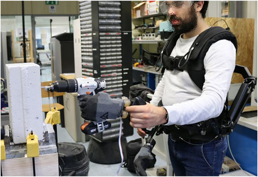
FIGURE 1. A subject drills a block of SIPOREX using the supernumerary system, which is composed of the Armor Man®, the Pisa/IIT SoftHand, and a customized damping wrist. The tool is held by the system, which contributes to a simultaneous load relocation and vibration transmission reduction.
While the joint load relocation provided by this SRL system could appear evident, vibration reduction requires a deeper analysis. Therefore, a simplistic lumped model of the system was explored with a one-direction analysis. In particular, during the drilling task, the drill bit is generally aligned with the user’s arm. For this work, this direction was considered the most affected direction for vibration transmission. In the following, we will refer to this as x-direction (or arm direction), according to a forearm-fixed reference frame with the x-axis parallel to it, pointing toward the hand (see Figure 2A). The system, integrated with the user’s arm, can be represented by a 2-DOF mass-spring-damper model, as shown in Figure 2B. The model was composed of three main sub-models, which represented, respectively, the human arm (HA), the gravity compensatory arm (Armor Man, AM), and the robotic hand with the damping wrist (SoftHand, SH). When a user grabs the distal part of the gravity compensatory arm (as shown in Figure 2A), the HA can be considered connected in parallel with the AM, and together they are serially connected to the SH through the damping wrist, which is represented by its physical properties of rigidity (
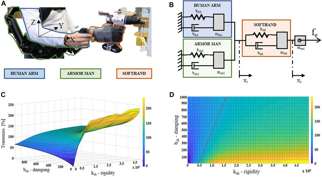
FIGURE 2. In (A), the lumped model of the presented supernumerary robotic system is shown. Parameters
It is worth noting that it is out of the scope of this work to design and estimate a new human arm model, and this section does not aim to provide an in-depth model identification analysis. With the following analysis, we are mainly oriented to theoretically contextualize and define the proposed system into the highlighted problem. For this reason, the HA sub-model is a 1-DOF mass-spring-damper model inspired by (Reynolds and Soedel, 1972), whose parameters are reported in the ISO 10068:2012 document. It should also be noted that the model used here is grounded, where the ground is represented by the rest of the human body over the shoulder level. This is in line with the assumption generally proposed in the literature for dealing with this kind of analysis (Rakheja et al., 2002; Matthiesen et al., 2018; Dong et al., 2007; Dong et al., 2013). Similar to the state of the art, in this work, the involved vibration magnitude is low enough for neglecting its transmission on superior substructures as the head, torso, and legs. Regarding the AM sub-model, the main influence in terms of damping and rigidity is caused by the padding of the vest, where the gravity compensatory arms are attached. This is because its vertical joints make the arm totally free to move in the investigated direction. The dynamic parameters
The dynamic response in the x-direction of the entire model is described by the following equations:
where
Considering the EU directive (2002/44/EC) and the ISO 5349, the vibration effect from a working tool must be evaluated by observing the acceleration transmitted on the human arm. In particular, the daily exposure A(8), i.e., the level of vibration exposure over an 8 h work period, needs to be estimated. It is calculated as follows:
where
where
where
As shown in Figures 2C,D, simulation results demonstrate how the custom wrist rigidity and damping parameters act on the vibration transmissibility. The first consideration comes from null values for both the parameters: as expected, this condition results in
Different transmissibility trends can be observed by augmenting one of the two parameters per time. Supposing a fixed
According to the simulation results and the system requirements listed above, the most optimal solution needs to have small (few centimeters) and light (less than
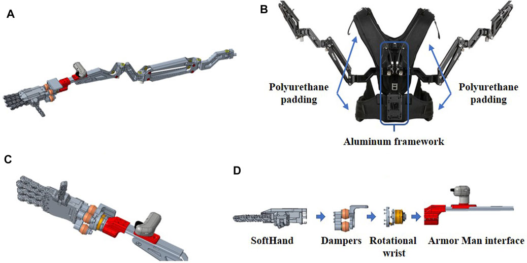
FIGURE 3. The 3D CAD model of the SRL is shown. Picture (A): the whole compensatory arm integrated with the robotic hand through the custom damping wrist. Picture (B) shows the Armor Man, highlighting main parts. Picture (C): details of the robotic hand with the custom damping wrist and the user handle. Picture (D): the exploded view of the hand-wrist assembly.
4 System Description
As mentioned in the previous sections, the new supernumerary robotic arm-hand system is composed of two gravity compensatory arms (the Armor Man 2.0, Tilta), integrated with two robotic hands, the SoftHand (Catalano et al., 2014), through a customized wrist damping mechanism. The use of additional robotic hands as end effector makes the system multi-purpose oriented since it allows for grasping many different kinds of objects and tools, varying in size and shape. This is an important feature both for expanding the user’s grasping capacity, like multiple objects/tools grasping or holding large objects, and for reducing hand risk exposure to hazardous materials or tools.
4.1 Gravity Support
The gravity compensatory arms (
4.2 Robotic Hand and Custom Damping Wrist
In order to grasp and manipulate objects without overloading the user’s wrist-hand-finger joints, an under-actuated and synergy-driven robotic hand (
5 Experimental Analysis
For investigating and quantifying the vibration reduction provided by this system, a work activity was simulated experimentally. Hand vibrations of seven male subjects were measured during a drilling task. Two different materials, SIPOREX and wood, were drilled with two different drill configurations. In this way, the system performance can be validated against different conditions. The two materials differ in terms of density, hardness, and friability, so there would be different vibration absorption, thus varying the quantity of vibration transmitted to the subject. In addition, the two drill configurations can introduce different kinds of vibrations in terms of magnitude, frequency, and directions.
5.1 Experimental Setup
To measure the vibration levels, two Inertial Measurement Units (IMUs) MPU-9250 MotionTracking (by InvenSens, Inc., San Jose, CA, United States) were used: one fixed on the dorsal side of each subject’s hand (see Figure 4A) and one on the backside of the drill (see Figure 4B). The acceleration from both IMUs was acquired by two custom electronic boards (Santina et al., 2017) (based on Cypress Programmable System on Chip-PSoC, with RS485 communication protocol), as shown in Figures 4A,B, with a sample rate of
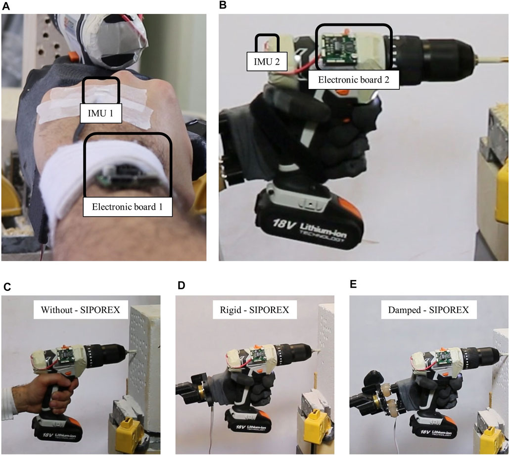
FIGURE 4. (A,B) The IMUs and the electronic boards for recording the acceleration on both the hand and the drill. (C–E) The drilling in phase with the SIPOREX, for the without, rigid, and damped configurations, respectively.
5.2 Experimental Protocol
To evaluate each system component's contribution (i.e., the robotic hand and the damping wrist) to the vibration reduction, a drilling task experiment was designed as follows. Seven male subjects were asked to make 12 holes in three different configurations:
• Without: by holding the hammer drill with their own hand (see Figure 4C);
• Rigid: by holding the hammer drill with the robotic hand rigidly connected to the compensatory arm with four screws (see Figure 4D);
• Damped: by holding the hammer drill with the robotic hand connected to the compensatory arm with the four dampers (see Figure 4E).
Each subject was asked to drill, with each configuration (see Figures 4C–E), both a block of SIPOREX and a piece of wood. To do this, the hammer drill was set at the maximum speed (1,400 rpm) impact/hammer OFF for the wood and at the minimum speed (400 rpm), and impact/hammer ON (6,400 bpm) for SIPOREX. The drilling task protocol, composed of four different phases, was fixed as follows:
1) Drill off: holding the drill while it is OFF;
2) Drill on: holding the drill after turning it ON;
3) Drilling in: drilling the material;
4) Drilling out: removing the drill from the material.
The identification of four phases for the drilling action was necessary because of the differences in time duration for each of them. According to the ISO 5349 document, the vibration evaluation is based on the r.m.s. values of the frequency-weighted acceleration vectors on each axis. However, during a hole drilling performance, stronger vibrations are generated during the drill bit interaction with the material, which generally is the fastest phase. On the contrary, a larger time is spent holding the drill and positioning it. In this way, calculating the r.m.s. on the entire action, the non-interacting phase may induce an underestimation of the real vibration exerted during the task.
Some precautions were considered to avoid differences in vibration transmission due to the robotic hand grasping force and drill velocity rotation. First, the drill trigger was maximally pushed using a Velcro strap. Then, the drill was fixed at the robotic hand, which grasped it with the maximum force at the beginning of the experiment and released it at the end. To stop the drilling, the battery connection/disconnection was used as an ON/OFF system. This was necessary between phases 1 and 2, where the subject needed to turn on the drill. Then, for the drilling on phase, each subject was asked to insert the drill bit for
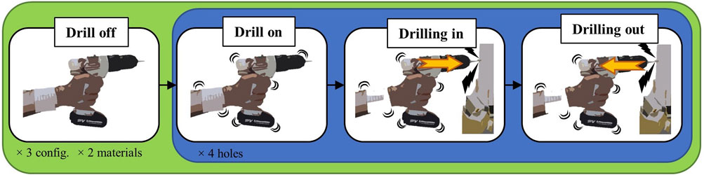
FIGURE 5. Workflow of the different experimental phases.
5.3 Data Analysis
In order to compare the effect of the different configurations tested, a within-subject analysis was conducted directly on the
In addition to the
where
5.4 Ethics
The study was reviewed and approved by the Regional ethics committee of Liguria (Protocol IIT-HRII-ERGOLEAN, 156/2020, DB-id 10,215). The participants provided their written informed consent to participate in this study and for the publication of any potentially identifiable images or data included in this article. The data that support the findings of this study are available from the corresponding author upon request.
6 Results
Numerical results are reported in Table 1 and graphically shown in Figure 6. SIPOREX results are presented first, followed by the wood results. The median values among the subjects are used for discussion. The outlier removal function identified and discarded a total of 73 outliers on the whole dataset (2,272 values).
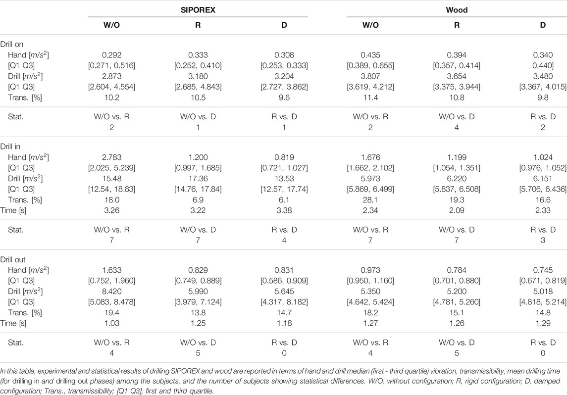
TABLE 1. Experimental results.
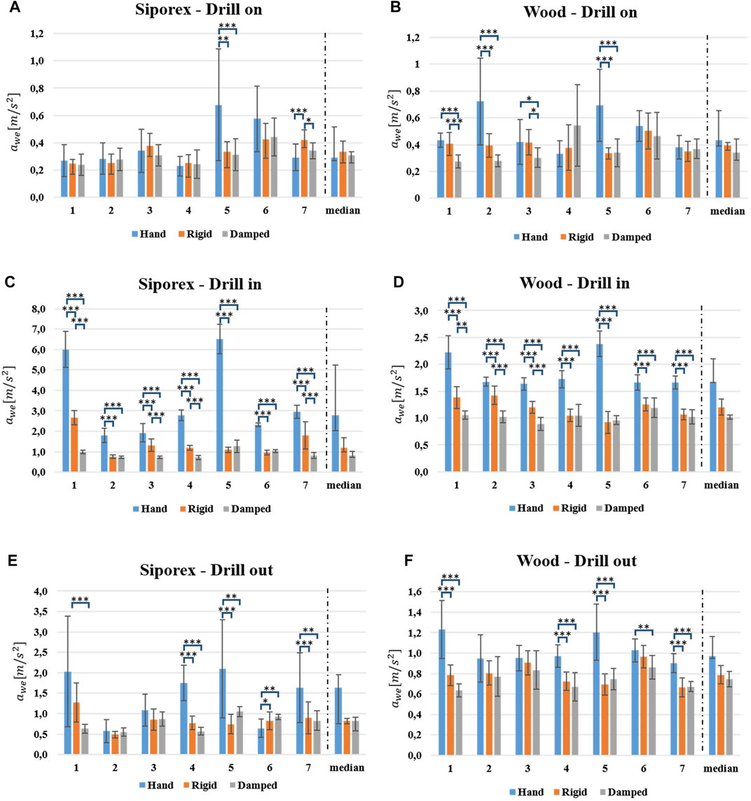
FIGURE 6. The
6.1 Drilling SIPOREX
During the drill on phase, the acceleration value measured on the hand (
During the drilling in phase, both
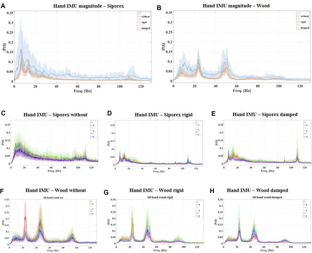
FIGURE 7. frequency spectra of the hand vibration during the drilling in phase for all the subjects are shown. In particular, (A,B) the spectrum of the magnitude acceleration for the three different configurations (without in light-blue, rigid in orange, and damped in gray) drilling in SIPOREX (A) and wood (B). (C,D,E) The frequency spectrum of the acceleration along the three axes (x in red, y in green, and z in blue) for the three different configurations in drilling SIPOREX; (F,G,H) the frequency spectrum of the acceleration along the three axes (x in red, y in green, z in blue) for the three different configurations in drilling wood. All the curves represent the median Discrete Fourier Transform among all the holes of all the subjects. Color bands represent the interquartile range.
For the last phase, the drilling out, both
6.2 Drilling Wood
Regarding the drill on phase, both
In the drilling in phase, both
Moreover, for the last phase, the drilling out, the
7 Discussions
In this work, the hand-transmitted vibration intensity was estimated through the index defined by ISO-5349, which uses the acceleration measurements on the subjects’ hands. Numerical results show an important reduction of the vibration transmission during drilling tasks, thanks to the proposed robotic system. In particular, during the drilling in phase, a reduction of the vibration transmission of the 60% (from 18 to 6% for SIPOREX) and of the 40% (from 28 to 16% for wood) has been measured (see Table 1). Interestingly, the absolute vibration, measured on the subjects’ hands (
To estimate the damping effect of the proposed SRL, the arm-hand acceleration was measured only on the back of the individuals’ hands; hence, the effects of vibration on sub-structures (e.g., palm skin and fingers) or distant ones (e.g., forearms, elbow and shoulder) were not investigated. This choice was motivated by the fact that the more distant the vibration source, the less its transmission (Xu et al., 2017). This implies that the back part of the hand can be considered as a “safe” measurement point for the upper sub-structures (from the wrist to the shoulder). On the other hand, for closer parts, as the palm skin and the fingers, it has been demonstrated that effective vibration transmission on these parts is generally over
In this work, the arm direction (x-direction in Figure 2) was considered the most affected in terms of vibration propagation, in particular during the hammering condition. The efficacy of the robotic system in this direction can be easily appreciated by the decreasing power of the frequency spectrum in drilling SIPOREX (with hammer ON) in different configurations, as shown in Figure 7. Additionally to the high power reduction of the low frequencies (compare Figure 7C with Figures 7D,E), an important vibration suppression is also present at the hammering frequency (
Another interesting outcome of this experimental analysis regards the execution time. It resulted in the same duration for all the tested configurations (without/rigid/damped), as reported in Table 1. This is an important point in terms of productivity and work efficiency since it guarantees that the robotic system does not introduce additional delays to the task execution. Future experiments will be oriented to investigate this point in relation to the drilling precision and quality.
Another potential advantage of the proposed system is the load redistribution capacity. Preliminary results on this aspect were reported by Ciullo et al. (2018). Based on the hardware design, we can ensure a significant load reduction not only on shoulder and elbow joints but also on other weaker and more vulnerable joints such as fingers and wrist. Different from most of the upper body exoskeletons (Toxiri et al., 2015; Martinez et al., 2008), with the presented SRL, the grasping action is mostly performed by the robotic hands. This solution can reduce or eliminate fingers and wrist joint overloading, which are anatomically weaker and smaller than the torso and legs (where the load is re-distributed thanks to the SRL). Such load reduction has also been demonstrated for deltoid and biceps muscles (Huysamen et al., 2018; Rashedi et al., 2014). However, the authors also highlighted undesirable effects on the antagonist muscles and low back, which may not be negligible. These can be due to the introduction of additional masses distributed far from the user’s center of mass (the robotic arm + hand), which induce additional forces/torques. According to the literature (Kim and Nussbaum, 2019; Huysamen et al., 2018; Rashedi et al., 2014), for a comprehensive investigation of advantages/disadvantages of using this kind of systems, three main conditions shall be addressed: 1) conducting the experiments in a more realistic environment, 2) collecting data of longer exposure, and 3) involving experienced workers for the experimental validations. Future works will be oriented in this direction to collect more data and define a more accurate pros/cons ratio.
8 Conclusion
In this work, a supernumerary robotic arm-hand system, based on a wearable commercial gravity compensator (Armor Man), a synergy-driven under-actuated robotic hand (SoftHand), and a custom damping wrist, was presented. The system was specifically designed to improve industrial worker ergonomics in two main aspects: minimizing the load on the worker’s arm joints and reducing the vibration transmission on their arms. The first was carried out thanks to the mechanical design of the gravity compensator combined with the robotic hand. In this way, an object can be directly grasped by the robotic hand and the load is translated from small joints (as fingers and wrist) to bigger and stronger ones (e.g., shoulder, torso, and legs). The custom damping wrist design also significantly reduced vibrations when using vibrating tools, which otherwise may cause a hand-arm vibration syndrome. Experimental results for drilling two different materials (SIPOREX and wood) reported a vibration transmission reduction from 40 to 60% with respect to the traditional hand drilling.
Data Availability Statement
The raw data supporting the conclusions of this article will be made available by the authors without undue reservation.
Ethics Statement
Written informed consent was obtained from the individual(s) for the publication of any potentially identifiable images or data included in this article.
Author Contributions
AC designed the system, analyzed data, and drafted the manuscript. MC and AA supervised the engineering process and data analysis and helped in drafting the manuscript. MC, AB, and AA supervised the research. All authors read and approved the final manuscript.
Funding
This work was partially funded by the EU Project H2020 SOPHIA (Grant Agreement No. 871237) and the ERC-StG Ergo-Lean (Grant Agreement No. 850932).
Conflict of Interest
The authors declare that the research was conducted in the absence of any commercial or financial relationships that could be construed as a potential conflict of interest.
Publisher’s Note
All claims expressed in this article are solely those of the authors and do not necessarily represent those of their affiliated organizations, or those of the publisher, the editors and the reviewers. Any product that may be evaluated in this article, or claim that may be made by its manufacturer, is not guaranteed or endorsed by the publisher.
Acknowledgments
The authors would like to thank M. Barbarossa, M. Maimeri, and M. Poggiani for their help in developing the setup and all subjects who participated in the study.
Supplementary Material
The Supplementary Material for this article can be found online at: https://www.frontiersin.org/articles/10.3389/frobt.2021.650613/full#supplementary-material
Footnotes
1Official Journal of the European Communities, Directive 2002/44/EC of the European Parliament and of the Council of 25 June, 2002.
References
Altenburger, R., Scherly, D., and Stadler, K. S. (2016). Design of a Passive, Iso-Elastic Upper Limb Exoskeleton for Gravity Compensation. Robomech. J. 3, 1–7. doi:10.1186/s40648-016-0051-5
Åström, C., Rehn, B., Lundström, R., Nilsson, T., Burström, L., and Sundelin, G. (2006). Hand-arm Vibration Syndrome (HAVS) and Musculoskeletal Symptoms in the Neck and the Upper Limbs in Professional Drivers of Terrain Vehicles-A Cross Sectional Study. Appl. Ergon. 37, 793–799. doi:10.1016/j.apergo.2005.09.004
Catalano, M. G., Grioli, G., Farnioli, E., Serio, A., Piazza, C., and Bicchi, A. (2014). Adaptive Synergies for the Design and Control of the Pisa/iit Softhand. Int. J. Robotics Res. 33, 768–782. doi:10.1177/0278364913518998
Ciullo, A. S., Catalano, M. G., Bicchi, A., and Ajoudani, A. (2018). A Supernumerary Soft Robotic Hand-Arm System for Improving Worker Ergonomics, 520–524. doi:10.1007/978-3-030-01887-0_101
da Costa, B. R., and Vieira, E. R. (2010). Risk Factors for Work-Related Musculoskeletal Disorders: a Systematic Review of Recent Longitudinal Studies. Am. J. Ind. Med. 53, 285–323. doi:10.1002/ajim.20750
Davenport, C., Parietti, F., and Asada, H. H (2012). Design and Biomechanical Analysis of Supernumerary Robotic Limbs, 787–793. doi:10.1115/dscc2012-movic2012-8790
De Looze, M. P., Bosch, T., Krause, F., Stadler, K. S., and O’Sullivan, L. W. (2016). Exoskeletons for Industrial Application and Their Potential Effects on Physical Work Load. Ergonomics 59, 671–681. doi:10.1080/00140139.2015.1081988
Della Santina, C., Piazza, C., Gasparri, G. M., Bonilla, M., Catalano, M. G., Grioli, G., et al. (2017). The Quest for Natural Machine Motion: An Open Platform to Fast-Prototyping Articulated Soft Robots. IEEE Robot. Automat. Mag. 24, 48–56. doi:10.1109/MRA.2016.2636366
Dong, J. H., Dong, R. G., Rakheja, S., Welcome, D. E., McDowell, T. W., and Wu, J. Z. (2008). A Method for Analyzing Absorbed Power Distribution in the Hand and Arm Substructures when Operating Vibrating Tools. J. Sound Vibration 311, 1286–1304. doi:10.1016/j.jsv.2007.10.031
Dong, R. G., Dong, J. H., Wu, J. Z., and Rakheja, S. (2007). Modeling of Biodynamic Responses Distributed at the Fingers and the palm of the Human Hand-Arm System. J. Biomech. 40, 2335–2340. doi:10.1016/j.jbiomech.2006.10.031
Dong, R. G., Welcome, D. E., McDowell, T. W., and Wu, J. Z. (2013). Modeling of the Biodynamic Responses Distributed at the Fingers and palm of the Hand in Three Orthogonal Directions. J. sound vibration 332, 1125–1140. doi:10.1016/j.jsv.2012.10.003
Griffin, M. J. (1997). Measurement, Evaluation, and Assessment of Occupational Exposures to Hand-Transmitted Vibration. Occup. Environ. Med. 54, 73–89. doi:10.1136/oem.54.2.73
Hammond III, F. L., Wu, F., and Asada, H. H. (2018), Variable Stiffness Pneumatic Structures for Wearable Supernumerary Robotic Devices, 201–217. doi:10.1007/978-3-319-51532-8_13
Hansson, G.-A., Balogh, I., Ohlsson, K., Granqvist, L., Nordander, C., Arvidsson, I., et al. (2010). Physical Workload in Various Types of Work: Part Ii. Neck, Shoulder and Upper Arm. Int. J. Ind. Ergon. 40, 267–281. doi:10.1016/j.ergon.2009.11.002
Hao, K. Y., and Ripin, Z. M. (2013). Nodal Control of Grass Trimmer Handle Vibration. Int. J. Ind. Ergon. 43, 18–30. doi:10.1016/j.ergon.2012.10.007
House, R. A. (2010). Hand-arm Vibration Syndrome. Tech. Rep Toronto: Discussion paper for the Workplace Safety and Insurance Appeals.
Howard, J., Murashov, V. V., Lowe, B. D., and Lu, M. L. (2020). Industrial Exoskeletons: Need for Intervention Effectiveness Research. Am. J. Ind. Med. 63, 201–208. doi:10.1002/ajim.23080
Hu, Y., Leigh, S.-w., and Maes, P. (2017). Hand Development Kit: Soft Robotic Fingers as Prosthetic Augmentation of the Hand. In Adjunct Publication of the 30th Annual ACM Symposium on User Interface Software and Technology. 27–29.
Huysamen, K., Bosch, T., de Looze, M., Stadler, K. S., Graf, E., and O'Sullivan, L. W. (2018). Evaluation of a Passive Exoskeleton for Static Upper Limb Activities. Appl. Ergon. 70, 148–155. doi:10.1016/j.apergo.2018.02.009
Kim, S., and Nussbaum, M. A. (2019). A Follow-Up Study of the Effects of an Arm Support Exoskeleton on Physical Demands and Task Performance during Simulated Overhead Work. IISE Trans. Occup. Ergon. Hum. Factors 7, 163–174. doi:10.1080/24725838.2018.1551255
Kim, W., Lee, H., Kim, D., Han, J., and Han, C. (2014). Mechanical Design of the Hanyang Exoskeleton Assistive Robot (Hexar), 479–484. doi:10.1109/iccas.2014.6988049
Kim, W., Lorenzini, M., Balatti, P., Nguyen, D. H. P., Pattacini, U., Tikhanoff, V., et al. (2019). Adaptable Workstations for Human–Robot Collaboration: A Reconfigurable Framework for Improving Worker Ergonomics and Productivity. IEEE Robotics & Automation Magazine, 26. IEEE, 14–26. doi:10.1109/MRA.2018.2890460
Ko, Y. H., Ean, O. L., and Ripin, Z. M. (2011). The Design and Development of Suspended Handles for Reducing Hand-Arm Vibration in Petrol Driven Grass Trimmer. Int. J. Ind. Ergon. 41, 459–470. doi:10.1016/j.ergon.2011.04.004
Laffranchi, M., Chen, L., Tsagarakis, N. G., and Caldwell, D. G. (2012). The Role of Physical Damping in Compliant Actuation Systems. 2012 IEEE/RSJ International Conference on Intelligent Robots and Systems. IEEE, 3079–3085. doi:10.1109/iros.2012.6385883
Lew, J. Y., and Moon, S.-M. (2001). A Simple Active Damping Control for Compliant Base Manipulators. Ieee/asme Trans. Mechatron. 6, 305–310. doi:10.1109/3516.951368
Lorenzini, M., Kim, W., De Momi, E., and Ajoudani, A. (2018). A Real-Time Graphic Interface for the Monitoring of the Human Joint Overloadings with Application to Assistive Exoskeletons, 281–285. doi:10.1007/978-3-030-01887-0_54
Martinez, F., Retolaza, I., Pujana-Arrese, A., Cenitagoya, A., Basurko, J., and Landaluze, J. (2008). Design of a Five Actuated Dof Upper Limb Exoskeleton Oriented to Workplace Help, 2008 2nd IEEE RAS & EMBS International Conference on Biomedical Robotics and Biomechatronics, 19-22 Oct. 2008, Scottsdale, AZ, USA, 169–174. 10.1109/BIOROB.2008.4762788
Matthiesen, S., Mangold, S., Germann, R., Schäfer, T., and Schmidt, S. (2018). Hand-arm Models for Supporting the Early Validation Process within the Product Development of Single Impulse Operating Power Tools. Forsch Ingenieurwes 82, 119–129. doi:10.1007/s10010-018-0265-1
Nguyen, P. H., Sparks, C., Nuthi, S. G., Vale, N. M., and Polygerinos, P. (2019). Soft Poly-Limbs: Toward a New Paradigm of mobile Manipulation for Daily Living Tasks. Soft robotics 6, 38–53. doi:10.1089/soro.2018.0065
Parietti, F., and Asada, H. H. (2014). Supernumerary Robotic Limbs for Aircraft Fuselage Assembly: Body Stabilization and Guidance by Bracing. In 2014 IEEE International Conference on Robotics and Automation (ICRA) (IEEE), Hong Kong, China, 29 September 2014, 1176–1183. doi:10.1109/icra.2014.6907002
Parietti, F., Chan, K. C., Hunter, B., and Asada, H. H. (2015). Design and Control of Supernumerary Robotic Limbs for Balance Augmentation, 5010–5017. doi:10.1109/icra.2015.7139896
Paulitsch, C., Gardonio, P., Elliott, S., Sas, P., and Boonen, R. (2004). Design of a Lightweight, Electrodynamic, Inertial Actuator with Integrated Velocity Sensor for Active Vibration Control of a Thin Lightly-Damped Panel. Proc. ISMA 2004, 239–253.
Prattichizzo, D., Malvezzi, M., Hussain, I., and Salvietti, G. (2014). The sixth-finger: a Modular Extra-finger to Enhance Human Hand Capabilities. The 23rd IEEE International Symposium on Robot and Human Interactive Communication. IEEE, 993–998. doi:10.1109/roman.2014.6926382
Rakheja, S., Wu, J. Z., Dong, R. G., Schopper, A. W., and Boileau, P.-É. (2002). A Comparison of Biodynamic Models of the Human Hand-Arm System for Applications to Hand-Held Power Tools. J. Sound Vibration 249, 55–82. doi:10.1006/jsvi.2001.3831
Rashedi, E., Kim, S., Nussbaum, M. A., and Agnew, M. J. (2014). Ergonomic Evaluation of a Wearable Assistive Device for Overhead Work. Ergonomics 57, 1864–1874. doi:10.1080/00140139.2014.952682
Reynolds, D. D., and Soedel, W. (1972). Dynamic Response of the Hand-Arm System to a Sinusoidal Input. J. Sound Vibration 21, 339–353. doi:10.1016/0022-460x(72)90818-8
Saraiji, M. Y., Sasaki, T., Kunze, K., Minamizawa, K., and Inami, M. (2018). Metaarms: Body Remapping Using Feet-Controlled Artificial Arms. In Proceedings of the 31st Annual ACM Symposium on User Interface Software and Technology. 65–74.
Song, P., Yu, Y., and Zhang, X. (2017). Impedance Control of Robots: an Overview. 2017 2nd international conference on cybernetics, robotics and control. Chengdu: CRC, 51–55. doi:10.1109/crc.2017.20
Stephen, B., Tatiana, Q., Robin, M., Michelle, M., Anna, V., and Leela, B. (2009). Fit for Work? Musculoskeletal Disorders in the European Workforce.
Tewari, V. K., and Dewangan, K. N. (2009). Effect of Vibration Isolators in Reduction of Work Stress during Field Operation of Hand Tractor. Biosyst. Eng. 103, 146–158. doi:10.1016/j.biosystemseng.2009.03.002
Toxiri, S., Ortiz, J., Masood, J., Fernández, J., Mateos, L. A., and Caldwell, D. G. (2015). A Wearable Device for Reducing Spinal Loads during Lifting Tasks: Biomechanics and Design Concepts, 2015 IEEE International Conference on Robotics and Biomimetics (ROBIO), Zhuhai, China, 6-9 Dec. 2015. IEEE, 2295–2300. doi:10.1109/robio.2015.7419116
Vatsal, V., and Hoffman, G. (2018). Design and Analysis of a Wearable Robotic Forearm. In 2018 IEEE International Conference on Robotics and Automation (ICRA) (IEEE), Brisbane, QLD, Australia, 21-25 May 2018, 5489–5496. doi:10.1109/icra.2018.8461212
Véronneau, C., Denis, J., Lebel, L.-P., Denninger, M., Blanchard, V., Girard, A., et al. (2020). Multifunctional Remotely Actuated 3-dof Supernumerary Robotic Arm Based on Magnetorheological Clutches and Hydrostatic Transmission Lines. IEEE Robot. Autom. Lett. 5, 2546–2553. doi:10.1109/lra.2020.2967327
Welcome, D. E., Dong, R. G., Xu, X. S., Warren, C., McDowell, T. W., and Wu, J. Z. (2015). An Examination of the Vibration Transmissibility of the Hand-Arm System in Three Orthogonal Directions. Int. J. Ind. Ergon. 45, 21–34. doi:10.1016/j.ergon.2014.11.001
White, S. W., Kim, S. K., Bajaj, A. K., Davies, P., Showers, D. K., and Liedtke, P. E. (2000). Experimental Techniques and Identification of Nonlinear and Viscoelastic Properties of Flexible Polyurethane Foam. Nonlinear Dyn. 22, 281–313. doi:10.1023/a:1008302208269
Keywords: supernumerary robotic limbs, ergonomics, vibration suppression, assistive robotic, robotic protective equipment
Citation: Ciullo AS, Catalano MG, Bicchi A and Ajoudani A (2021) A Supernumerary Soft Robotic Limb for Reducing Hand-Arm Vibration Syndromes Risks. Front. Robot. AI 8:650613. doi: 10.3389/frobt.2021.650613
Received: 10 February 2021; Accepted: 07 July 2021;
Published: 17 August 2021.
Edited by:
Ashwin Dani, University of Connecticut, United StatesReviewed by:
Haohan Zhang, Columbia University, United StatesNaveen Kuppuswamy, Toyota Research Institute (TRI), United States
Pavan Nuthi, University of Texas at Arlington, United States
Copyright © 2021 Ciullo, Catalano, Bicchi and Ajoudani. This is an open-access article distributed under the terms of the Creative Commons Attribution License (CC BY). The use, distribution or reproduction in other forums is permitted, provided the original author(s) and the copyright owner(s) are credited and that the original publication in this journal is cited, in accordance with accepted academic practice. No use, distribution or reproduction is permitted which does not comply with these terms.
*Correspondence: Andrea S. Ciullo, YW5kcmVhLmNpdWxsb0BpbmcudW5pcGkuaXQ=