- Science and Technology of Robots in Medicine (STORM) Laboratory, School of Electronics and Electrical Engineering, University of Leeds, Leeds, United Kingdom
The growing interest in soft robotics has resulted in an increased demand for accurate and reliable material modelling. As soft robots experience high deformations, highly nonlinear behavior is possible. Several analytical models that are able to capture this nonlinear behavior have been proposed, however, accurately calibrating them for specific materials and applications can be challenging. Multiple experimental testbeds may be required for material characterization which can be expensive and cumbersome. In this work, we propose an alternative framework for parameter fitting established hyperelastic material models, with the aim of improving their utility in the modelling of soft continuum robots. We define a minimization problem to reduce fitting errors between a soft continuum robot deformed experimentally and its equivalent finite element simulation. The soft material is characterized using four commonly employed hyperelastic material models (Neo Hookean; Mooney–Rivlin; Yeoh; and Ogden). To meet the complexity of the defined problem, we use an evolutionary algorithm to navigate the search space and determine optimal parameters for a selected material model and a specific actuation method, naming this approach as Evolutionary Inverse Material Identification (EIMI). We test the proposed approach with a magnetically actuated soft robot by characterizing two polymers often employed in the field: Dragon Skin™ 10 MEDIUM and Ecoflex™ 00-50. To determine the goodness of the FEM simulation for a specific set of model parameters, we define a function that measures the distance between the mesh of the FEM simulation and the experimental data. Our characterization framework showed an improvement greater than 6% compared to conventional model fitting approaches at different strain ranges based on the benchmark defined. Furthermore, the low variability across the different models obtained using our approach demonstrates reduced dependence on model and strain-range selection, making it well suited to application-specific soft robot modelling.
Introduction
Over the last few decades, there has been growing interest in the field of soft robotics (Lipson, 2014; Rus and Tolley, 2015). These robots offer many advantages over their rigid body counterparts, with the ability to traverse complex trajectories to reach previously inaccessible areas, deform both actively and passively in multiple directions, and interact safely within delicate environments (e.g., with biological tissues). Furthermore, they often represent simpler fabrication and assembly with respect to rigid robots with joints; being molded in monolithic material designs (Chandler et al., 2020), with embedded strain limiting materials (Mosadegh et al., 2014; Polygerinos et al., 2015) or with the addition of functional components (e.g., magnetic particles) (Kim et al., 2019; Lloyd et al., 2019). These advantages are afforded due to the highly compliant nature of the materials from which they are typically made, and have made soft robots (SRs) a popular choice for small-scale medical and surgical instrumentation (Cianchetti et al., 2014, 2018; da Veiga et al., 2020); from common grasping tasks (Zhang et al., 2017b), endoscopic (Chauhan et al., 2021; Liu et al., 2021) and minimally invasive surgery (Edelmann et al., 2017; Oliver-Butler et al., 2017; Jeon et al., 2019) to microfluidic platforms in order to stimulate and sort cells (Zhang et al., 2017c; Onaizah et al., 2020).
Actuation of SRs is possible using numerous methods, including, for example, pneumatic, hydraulic, mechanical, chemical and magnetic approaches (Burgner-Kahrs et al., 2015; Le et al., 2016; Thuruthel et al., 2018). However, in the case of medical and surgical applications, the use of magnetic actuation is particularly advantageous as it allows for improved device scalability since mechanical transmission and on-board power and electronics can be removed (Abbott et al., 2020; da Veiga et al., 2020). Forces and torques are generated wirelessly due to ferromagnetic bodies embedded inside the robot interacting with a local or global magnetic field often generated by electromagnetic coils (Kummer et al., 2010; Petruska and Abbott, 2014; Sikorski et al., 2017) or permanent magnets (Pittiglio et al., 2020). Magnetically actuated soft robots (MASRs) can be produced in two different ways: a soft elastomeric matrix can be created using magnetic powder mixed with the soft materials before the robot is molded (Lum et al., 2016; Zhang C. et al., 2017; Kim et al., 2019; Lloyd et al., 2019) or a permanent magnet can be placed inside a cavity of the already fabricated SR (Jeon et al., 2019; Tariverdi et al., 2021). Each approach has its advantages and disadvantages with permanent magnets offering a higher magnetic material density and thus larger forces and torques for a given external field but also adding a rigid domain to the robot. Using an elastomeric matrix, on the other hand, offers the advantages of maintaining an entirely compliant device, however, introduces changes to the base elastomer material properties and thus characterization is limited to that specific matrix (da Veiga et al., 2021).
As with SRs actuated using alternative means, MASRs are manufactured using soft elastomeric polymers with elastic moduli values close to those of biological tissues. While these highly compliant materials support safer tissue interactions in surgical applications, they are much harder to model and thus predict their behavior. Under actuation, the hyperelastic material can produce highly nonlinear deformations that cannot be resolved using techniques conventionally used in robotics. As noted in the research conducted by Chen and Wang (2020), the preferable way to test and optimize a SR during the early stages of the design is through finite element analysis (FEA). If a FEA model is well defined, it can accelerate the process of design optimization, reducing the need for repeated experimentation and thus lowering the cost.
Several material models of varying complexity have been proposed (Mihai and Goriely, 2017), including: Neo Hookean, Yeoh, Mooney-Rivlin and Ogden models. These models aim to deliver a relationship between the principal stresses and the deformation of the material when subject to a mechanical load. The most popular procedure for characterizing a specific hyperelastic material, under the hypothesis of isotropy and incompressibility, involves a mechanical tensile test up to material failure to collect the stress-strain data (Marechal et al., 2020). While tensile testing based experiments are the most popular way to characterize the material model, these have some limitations including that the strain produced in the gauge area of the specimen may be larger than the strain measured globally (Krautz et al., 2017). One way to solve this problem is through image correlation by observing the strain locally in the gauge area (Hartmann et al., 2003; Meunier et al., 2008). While this technique seems promising, it may not be widely accessible. Furthermore, tensile tests miss information like shear stress that often requires the use of more complex testing, such as equiaxial testing (Steinmann et al., 2012) or volumetric testing (Horgan and Murphy, 2009) which requires multiple experimental platforms and can be expensive and time-consuming.
In addition, soft materials will deform several times their original length before the fracture point is reached during a mechanical test. While this data is relevant for some applications such as pneumatically actuated SRs (Mosadegh et al., 2014), in other applications, the forces and torques applied on the material generates only a fraction of the deformation experienced by the specimens during the tensile test (Steck et al., 2019). Furthermore, using the entire tensile test dataset to fit the parameters for lower order models can introduce considerable errors in the region of interest as the models may overestimate or underestimate the stiffness (see Figure 1), limiting the fidelity of associated FEA simulations. A reduced set of the experimental data, bounded by the maximum expected strain, may mitigate these issues. However, to decide a priori the expected strain can be challenging. Increasing the order of the material model represents another method to reduce fitting errors, however, this can be potentially harmful to the robustness and the stability of the simulation (Schumacher et al., 2020). Previous work has tried to improve the stability and performance of the modelling by using FEA simulation to fit the model parameters (Hartmann et al., 2003; Fu et al., 2013; Schumacher et al., 2020; Hartmann and Gilbert, 2021). The main idea behind this approach is to find the parameters of the material model by solving an inverse optimization problem. This system explores the search space in order to minimize the error between the finite element analysis and the experimentally obtained data. While these techniques may be useful for large deformations; the potential disparity between local strains in the gauge and the globally measured strains still exists.
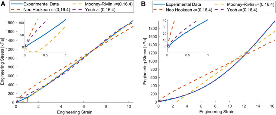
FIGURE 1. When the material models are trained using the entire set of tensile data, the error from the model in the region of interest may be considerable. In this case, we highlight this effect by zooming into a smaller strain range (100%), for (A) Dragon Skin™ 10 MEDIUM and (B) Ecoflex™ 00-50 where there is a significant variance between the models and experimental data. Ogden model excluded for readability [Data and the Code provided by Marechal et al. (2020)].
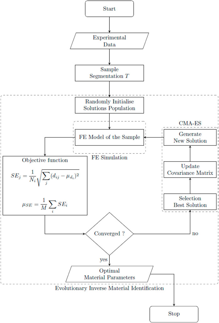
To address these issues, we propose Evolutionary Inverse Material Identification (EIMI), a material characterization approach aimed at identifying the parameters for a material based on the target application, in our case: MASRs. We aim to characterize materials by using a simulated representation actuated using the same method as used during experiments. Having defined a simulation model, we can then create, deform and observe an equivalent specimen of soft material in a real, controlled environment. Finally, we define an optimization problem where the parameters of the material model comprise the search space while the error between the experimental data and the simulation is minimized. The problem defined is often non-linear and gradient methods may fail to find an optimal solution. We address this issue by using, for the first time, an optimizer based on an evolutionary strategy. An evolutionary algorithm (EA) allows a good balance between exploitation and exploration of the search space (Neri and Tirronen, 2010; Deb, 2014). This technique has several benefits, first, using a simulation model to search the parameters for the material allows us to obtain a result that guarantees robustness and increases the performance of the simulation. Second, by using the same actuation method in the simulation and experiment, our resulting material model will be optimized for the target application. This is because EIMI will intrinsically reduce the error between the observed stress and the predicted stress from the analytical model. Moreover, using EIMI over the conventional tensile testing approach may solve the problem of heterogeneous deformation encountered by the specimen.
In the next section, our framework for material characterization is presented. First, we define the FEA model and the fabrication steps to create the equivalent experimental sample. Next, using the proposed comparison metric, we discuss the steps to minimize the fitting errors using an EA. To demonstrate our characterization approach, we focus on a MASR, made using two soft polymers commonly found in soft robotics applications: Ecoflex™ 00-50 and Dragon Skin™ 10 Medium. Finally, in the Experimental Evaluation section the performances of the models are characterized using the framework presented, and the resulting model parameters are compared with the model parameters obtained using the conventional fitting approach.
Characterization Framework
To demonstrate our characterization approach, we first developed a FEA model of a simple MASR. The design takes the form of a rectangular body with a small permanent magnet embedded at the distal end, as shown in Figure 2. The body of the MASR bends in response to a magnetic torque generated from the interaction between the embedded magnet and a globally applied magnetic field. We defined a procedure to allow comparison between the FE simulation and the experimental data; thus, developing an objective function for the optimization problem. Comprehensive details of our approach are presented in the following sections.
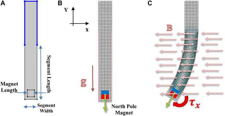
FIGURE 2. Simulated representation: (A) geometry of the sample is shown; (B) mesh used for the FEM simulation, the direction of the magnetic field, as well as the magnetization direction M, are shown; (C) an example simulation result is also shown.
FEA Model
As previously mentioned, conventional uni-axial mechanical tests on soft materials deform standardized samples over several times their original length (Marechal et al., 2020). However, in more realistic soft robotic applications, especially those driven via magnetic fields, the material may experience only a fraction of these deformations. To improve fidelity between testing for characterization and application, we propose simulating the application-specific actuation method (i.e., magnetically induced forces and torques) within the FEA simulation and solving an optimization problem using an EA to characterize the material. Due to the nature of the EA, the simulation model may be invoked many times, with the potential to significantly increase computational time. Therefore, we developed our FEA model with a balance between accuracy and computational cost to simulate the magneto-mechanical response of our soft robotic designs. This combines analytical mechanical models used to predict nonlinear elastic behavior of polymers with magnetic interaction forces and torques based on a dipole approximation (Petruska and Abbott, 2013; Abbott et al., 2020).
For the mechanical model, we consider soft materials to be homogenous and isotropic. In previous work, it has been shown that compressibility and viscoelasticity may be neglected for lower strains (Steck et al., 2019). In general, to represent the deformed configuration
where

TABLE 1. Strain Energy functions for incompressible hyperelastic materials (Mihai and Goriely, 2017).
The soft material of the FE simulation is then deformed through the interaction with a rigid body, in our case a permanent magnet. The forces f and torques
where
A global coordinate system can be established since the magnetic actuation is the result of an external magnetic field interacting with the magnet. We consider actuation within a 2D plane, therefore, only one component of the magnetic field is non-zero. We define this to be the
Finally (see Sample Fabrication and Experimental Setup section), body forces due to gravity were integrated in the simulation model, to reconcile with the experimental setup.
The geometry and constraints of the MASR were selected to allow reduction of the model to a 2D plane (Figure 2A), and thus to perform 2D simulations with computational efficiency, by considerably reducing the nodes of the mesh and therefore the complexity of the system. The model so defined can be assumed as plane strain, since the cross-sectional thickness is sufficiently large to consider the depth dimension of the strain tensor equal to zero. For each simulation, geometry of the design was varied using 3 parameters: the length and the width of the robot, and the length of the magnet to match the physical dimensions of the MASR. A quadrilateral mesh was then generated based on the planar geometry (see Figure 2B), and the mesh size was determined after a dependency analysis over the magnet displacement for a fixed magnetic flux density of 15 mT. The magnet was positioned within the robot body with the magnetization direction (north pole) oriented towards the distal end. Therefore, the magnetization direction of the magnet and the externally applied field are perpendicular when the sample is in the resting position, thus maximizing torque (see Figure 2B). The simulation model response may then be evaluated for a range of magnetic fields (Figures 2C, 5B), in line with experimental testing. The model was implemented using COMSOL Multiphysics®. V5.4 (COMSOL, Sweden) and solved using Multifrontal Massively Parallel Sparse direct Solver. The number of quad mesh elements used for each geometry are summarized in Table 2.
Sample Fabrication and Experimental Setup
To provide experimental data for the optimization, samples were prepared and tested under a varying magnetic field. Four versions of the design were prepared with the geometrical parameters summarized in Figure 2. One of these geometries (Type 1) was used for training the material characterization through the optimization algorithm, while the others were used for validation (Type 2, 3, 4).
Molds were created for each geometry using a 3D Printer (Ultimaker S5), as shown in Figure 3. Samples were created using two soft elastomers: Dragon Skin™ 10 Medium and Ecoflex™ 00-50 (Smooth-on Inc., United States). For each material, the two-part components were mixed in equal weight using a high vacuum-mixer (Arv-10 from THINKYMIXER, Japan), at a pressure of 20 kPa for 90 s with the centrifuge set at 1,400 rpm to thoroughly mix and remove any air bubbles. A volume of material equal to two times the size of the specimen was slowly injected from the bottom of the mold and residual bubbles and excessive material were expelled using a port at the top of the mold. The material was allowed to cure at room temperature as specified by the manufacturer (5 h for Dragon Skin™ 10 Medium and 3 h for Ecoflex™ 00-50). Once cured, the samples were demolded and the appropriately sized magnets (grade N52, K&J Magnetics Inc., United States) were inserted in the pre-allocated space, with the magnetization direction (north pole) pointing towards the distal end of the MASR.

FIGURE 3. Fabrication steps for magnetic robots are shown: (A) injection of the silicone in the negative mold; (B) curing of the silicone; (C) magnet insertion (D) image of the mold and sample.
As shown in Figure 4, samples were tested using a uniform magnetic field, generated using a 1D Helmholtz Coil (DXHC10-200, Dexing Magnet Tech. Co., Ltd., Xiamen, China). During the experiment, the current in the coil was increased in discrete amounts. As a result, the magnetic field was increased proportionally to the current in the coil as described by Eq. 6 (Abbott et al., 2020).
where
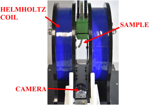
FIGURE 4. Experimental setup for testing magnetic robots. The sample is mounted in the center of the Helmholtz Coil and the deflection is captured using a side-view camera.
To extract image features intrinsically rich in information that could be used to compare the experimental deformation with the simulation model, we developed a post-processing procedure to measure the outer edges of the sample. Bespoke image processing code was developed using MATLAB (Image Processing Toolbox, MathWorks, United States), to allow segmentation and edge extraction where the deflection/deformation is more prominent along the longitudinal length of the sample. The following steps were followed: 1) high contrast images were obtained; allowing the sample edges to be easily extracted; 2) the boundary of the object was extracted, and the corners of the sample were determined from the edges; and 3) after splitting the edge of the sample into different segments, the relevant ones were saved to be used as a target in the characterization process (see Figure 5A).
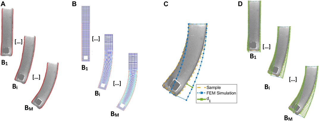
FIGURE 5. The steps used to obtain the distance between the FE simulation and the experimental data (see Eq. 10): (A) image segmentation and feature extraction of the left and right edge of the robot; (B) FEM simulation for a chosen model and parameters
Benchmark Functions
After the simulated and experimental results were obtained, a metric was needed to compare the two and allow for optimization. We propose the following approach to solve the problem where for each value of the magnetic flux density (
where
The metric in Eq. 10 was used to compare the different material models and as an objective function for the parameter fitting. In addition, the standard deviation (
Algorithm Development and Application
Here, we defined an optimization problem that allows fitting of the material parameters for a specific analytical model (Table 1). With the goal of minimizing the error by varying the parameters
where the parameters of the hyperelastic models are subject to upper and lower bounds based on physical constraints. The dimension of
EAs are, in general, based on some stochastic phenomena. This allows a random walk in the search space to improve the exploration features. Furthermore, these types of algorithms do not require complete information about the problem landscape. These characteristics made this type of algorithm an ideal solution for the problem defined here. In general, EAs are defined as a cyclic process with specific steps (see Figure 6). Initially, a random solution or set of solutions is created, then a two-step process is repeated for several generations (cycles) until the result converges. The first step involves a selection process where the best model parameters are chosen based on the metric (Eq. 10). These solutions are then used to generate new solutions through a stochastic procedure that will replace the solution discarded in the previous step, The stochastic procedure for generating newer solutions is partially based on the information contained in the solution that survived the selection phase (Deb, 2014).
In our framework, solutions that don’t comply with Drucker’s Stability are immediately discarded in the selection phase, specifically, any result that did not converge to a residual error
Several EA strategies have been proposed, however, one of the most successful to date has been the Covariance Matrix Adaptation Evolution Strategy (CMA-ES) (Hansen and Ostermeier, 2001). This algorithm has shown great potential for solving complex problems compared to other optimization strategies (Caraffini et al., 2013, 2019). This search strategy selects the best solution
Experimental Evaluation
We characterized two elastomers: Dragon Skin™ 10 Medium and Ecoflex™ 00-50 (Smooth-On Inc, United States). Four samples for each material were created using the dimensions listed in Table 2. The samples were magnetically actuated in the Helmholtz coil, by increasing the current in the coils incrementally from 0 to 1.5 A in steps of 0.1 A for Dragon Skin™ 10 Medium and from 0 to 1 A in steps of 0.1 A for Ecoflex™ 00-50. The current can be translated to magnetic flux density with a conversion factor of 4.7 mT/A. The deformation at each current step was recorded, and the samples were segmented (Figure 5). The resulting database was then split based on geometry. The samples with the Type 1 geometry (Table 2) were used for the material fitting while the rest were used for validation.
EIMI Analysis
The data from the samples chosen for the material characterization are used to define the optimization problem (see Benchmark Functions section) to solve the CMA-ES. The number of evaluations and generations required by the CMA-ES to converge to an optimal solution and obtain a set of model parameters are shown in Table 4. With an increasing number of parameters in the material model, the table displays the growth in the number of generations that were required to converge. This is expected, as they represent a complex objective landscape that is more difficult to explore. The table also shows an outlier, due to the stochastic nature of the EA. The characterization of Ecoflex™ 00-50 using the Ogden model required only 8 generations, despite the search space having high dimensionality with 6 model parameters.

TABLE 4. Number of function evaluations and generations required by the CMA-ES to characterize the materials.
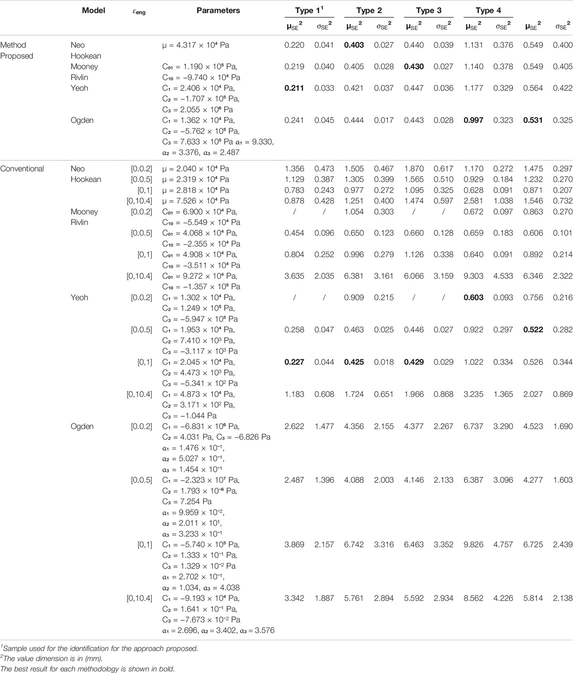
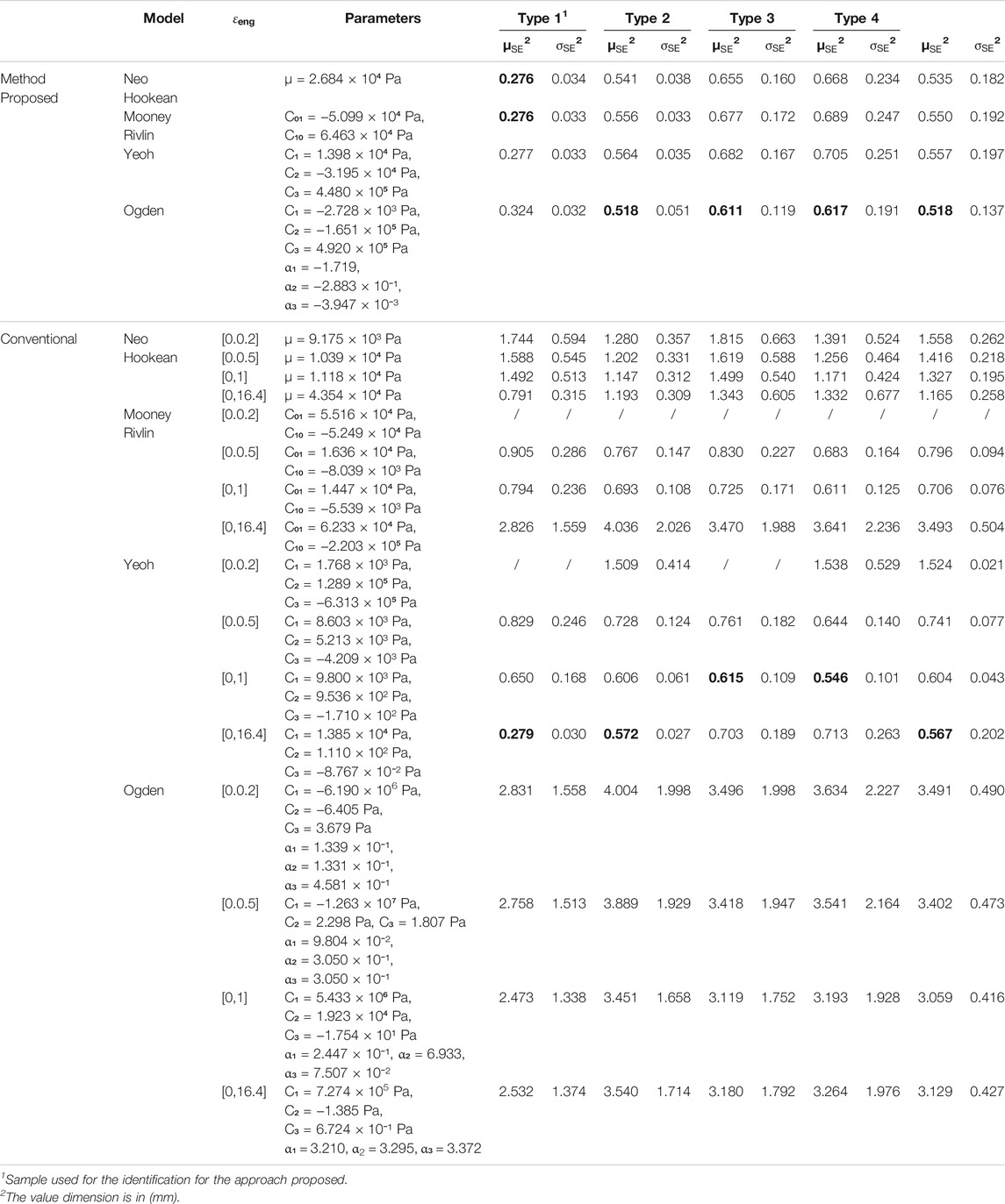
The parameters for the models obtained using EIMI are shown respectively on the top halves of Table 5 for Dragon Skin™ 10 Medium and Table 6 for Ecoflex™ 00-50. The two tables list the mean of the standard error and mean of the standard deviation using Eqs 10, 11 for each type of geometry and model using both our approach and the conventional approach (detailed below).
The results for Dragon Skin™ 10 Medium (see Table 5) show that there is a superior fit achieved for the Type 1 geometry which is the sample used for training. This result can be easily justified from the nature of the process used for characterization. The EA will tend to overfit the parameters for the sample used for training. We can also see that the standard error for the Neo Hookean, Mooney-Rivlin and Yeoh analytical models falls in the 95% confidence interval, making these analytical models similar in performance, as shown in Figure 7A. The Ogden model, however, falls outside of the confidence interval. The number of generations for the Ogden model is higher but could still be insufficient due to a higher number of parameters. To assess the generality of the model characterizations, we evaluated the errors for the other three geometries using the solution obtained by EIMI. For the Type 2 and Type 3 geometries, the standard error for the analytical models falls inside the 95% confidence interval (see Figure 7A). Finally, for the Type 4 geometry, the fitting error of the model parameters is larger. The errors may be caused by different factors, such as in segmentation of the experimental image, or an undesired torsion of the sample as observed during experimental testing (see Sample Type 4 in Figure 8A) (Lloyd et al., 2021) which is not captured within the 2D simulation.
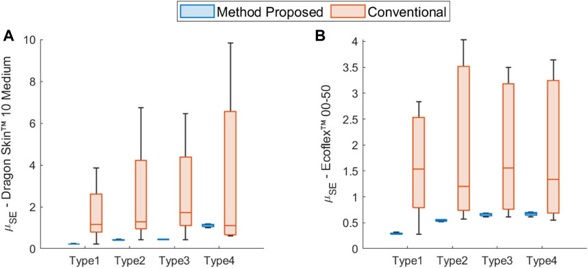
FIGURE 7. Comparison of the statistical distribution of the standard error mean (see Eq. 10) between the models obtained through the proposed EIMI and the conventional fitting approaches across the different geometry types for (A) Dragon Skin™ 10 Medium and (B) Ecoflex™ 00-50.
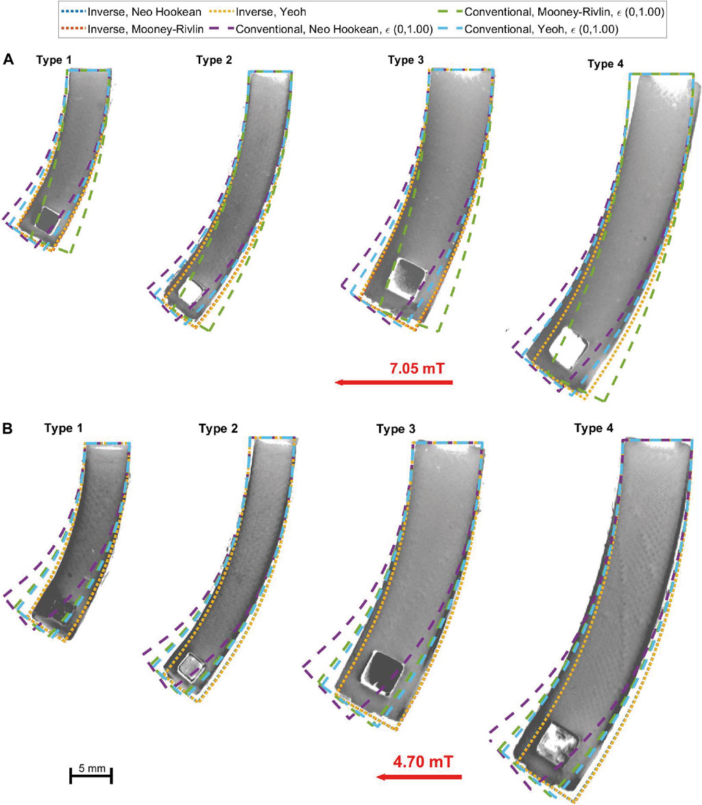
FIGURE 8. Comparison between material models and experimental images for (A) Dragon Skin ™ 10 Medium samples under a magnetic flux density of 7.05 mT (top half) and (B) Ecoflex™ 00-50 samples under a magnetic flux density of 4.7 mT (bottom half).
For Ecoflex™ 00-50 (see Table 6), the proposed approach showed similar results to Dragon Skin™ 10 Medium. For the Type 1 geometry, the method showed a tendency of overfitting the models with the number of parameters less than or equal to 3. The modelling errors were also within a confidence interval of 98% (see Figure 7B). Again, the Ogden model has the worst performance for this geometry despite a fast convergence. The optimizer is able to achieve fast convergence for the Ogden model by increasing the dimension of the decision space; however, this results in a more complex landscape that is difficult to explore since more local minima can influence the search. The mean standard error
Comparison Between EIMI and the Conventional Approach
To further understand the potential of the EIMI approach, we compared it to the conventional approach of fitting material models to experimental uni-axial tensile test data. Here we take advantage of the data and the code provided by Marechal et al. (2020). For each material model analyzed (Table 1), we fit each of the hyperelastic models analyzed using the same tensile data bounded for different engineering strains. More specifically, we fit the models to consider tensile test data for strains of: 20, 50, 100% of the deformation and the full tensile dataset. The obtained parameters and associated errors are shown in the lower part of Tables 5, 6 for Dragon SkinTM 10 Medium and EcoflexTM 00-50 respectively, and in Figure 7. As can be seen in both cases, the conventional approach typically produces larger errors when compared to the EIMI approach. In twenty-one of the twenty-four cases, the overall improvement with EIMI was above 26%.
For the Dragon Skin™ 10 Medium (Table 5), the Yeoh model fit via the conventional method with strains constrained to 50 and 100% of the original length, produced similar results to EIMI; with the latter showing modest improvement of below 2% against the best two models using the conventional approach. However, choosing the most appropriate engineering strain range for fitting purposes is not a trivial matter. The other analytical models (with different strain ranges) using the same dataset failed to get close to the same results, with the EIMI showing at least a 30% improvement. This underlines the difficulty of choosing the most suitable analytical model and the correct stress-strain selection over the tensile data.
Interestingly, for Ecoflex™ 00-50 (Table 6), the best overall performance with the conventional fitting was obtained again using the Yeoh model using the full range (16 times the original length) of strain data for Type 1 and Type 2 geometries and 100% strain for Type 3 and Type 4. Our EIMI showed a performance improvement of 6.8% compared to the best model which in this case was Ogden. For the rest of the cases, EIMI showed an improvement of at least 26%. This result again illustrates how difficult it is to pre-determine the correct range of tensile data to use in order to fit analytical models.
Overall, it is possible to see that the models fit using a conventional approach over different ranges of stress-strain data failed to converge to similar results. The box plots in Figure 7 show a higher variance between conventional models fit using the same tensile range. On the other hand, all the models obtained using the EIMI converge to similar performance values, validating the procedure. Thus, the proposed EIMI method showed that it is capable of dynamically fitting the models without any previous knowledge of the strain involved.
The performance of the different models can be clearly seen in Figure 8 where we can qualitatively observe that our proposed method shows improved performance. In both pictures, the models obtained using EIMI are compared with the models trained using tensile data with a strain of up to 100%. In general, it is possible to see that EIMI is able to produce a better result regardless of the complexity of the model, with similar responses across the different models. Whereas the model fitted using the conventional approach drifts considerably from the experimental data. For Dragon SkinTM 10 (see Figure 8A), it is possible to see that the Neo Hookean and the Yeoh models underestimated the stiffness, while the Mooney-Rivlin model overestimated the stiffness. For EcoflexTM 00-50 (Figure 8B) all 3 models underestimated the stiffness.
To understand how performance varies with actuation, we analyzed EIMI and the best models found using the conventional approach for each of the magnetic field values tested. More specifically we analyzed the SE (see Eq. 9) at each magnetic field value
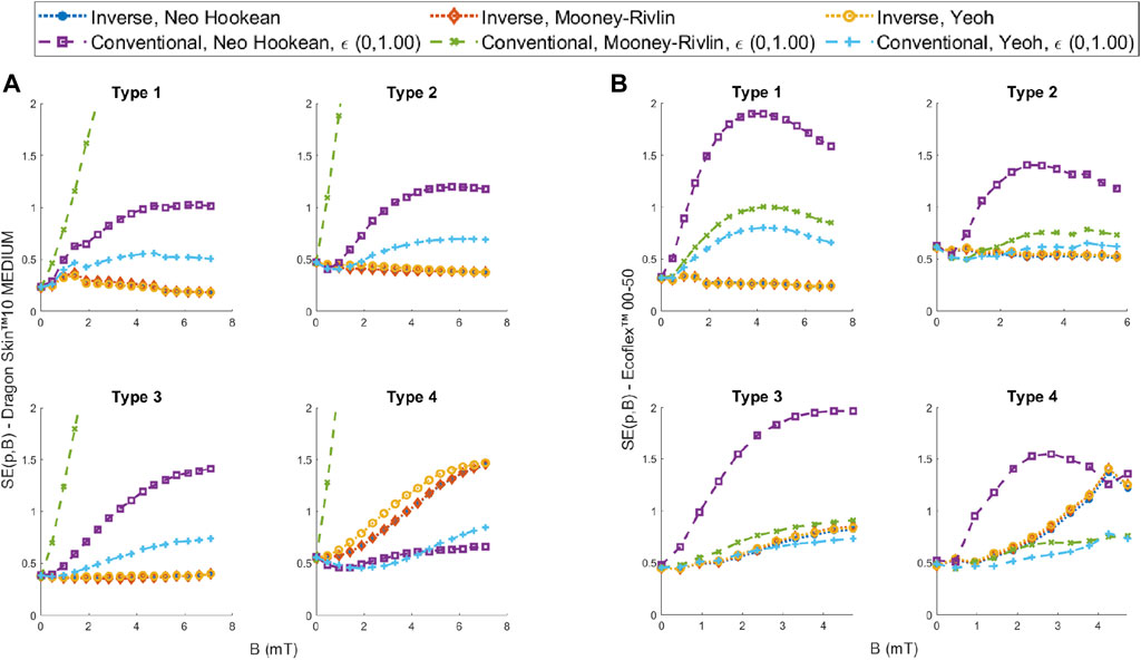
FIGURE 9. SE comparison between the models fitted using the EIMI and the conventional method using 100% of the engineering strain for increasing magnetic fields for (A) Dragon Skin™ 10 Medium and (B) Ecoflex™ 00-50.
The performance of the Dragon Skin™ 10 Medium is shown in Figure 9A. For geometry Types 1, 2 and 3, all the models obtained using our EIMI approach produce a smaller error than the best performer (Yeoh) from the conventional approach. Furthermore, the error is constant with the increasing magnetic field, while for the other models it increases with the magnetic field. For Type 4, we see that the conventional Yeoh and Neo Hookean models have a smaller error across all field values. This was due to an observed twisting in the sample that reduced the bending of the beam, which can be interpreted as a stiffer material in the 2D plane (see Supplementary Video S1). This is why we see the errors obtained using the EIMI approach steadily increasing for the Type 4 geometry.
For Ecoflex™ 00-50 (see Figure 9B), we can see that for the sample used for training (Type 1) the models obtained using EIMI outperform all other models. For Types 1 and 2 samples, the Yeoh and Mooney-Rivlin models fitted over 100% strain of tensile data showed slightly worse performance compared to the EIMI and have a similar trend in the SE with the increasing magnetic field. However, these models outperform the EIMI for higher values of the magnetic field in Type 4, again likely due to the twisting of the sample observed experimentally (see Supplementary Video S1).
Overall, our proposed approach is able to maintain a steady error (Figure 9) with increasing magnetic field showing that it is able to dynamically follow the deflection of the robot.
Conclusion and Future Development
In this work, we presented an alternative method of material characterization to dynamically find the best material model based on the target application. We present a framework for characterizing hyperelastic materials using an FEA simulation, application-specific experimental evaluation and an EA to solve the optimization problem. The results show that the proposed EIMI approach can fit the parameters for a material model with a high degree of accuracy. Furthermore, thanks to the use of the simulation model in the characterization process, we can intrinsically obtain robust and stable models to use with numerical methods.
Our results also highlight the inherent challenges with the conventional model-fitting approach. In this study, we rely on the database of Marechal et al. (2020), where the models are fitted by minimizing the standard error between the experimental data and simulation to allow the reader to easily verify and evaluate new models. However, other strategies such as the minimization of the relative errors may be considered to improve the material characterization (Destrade et al., 2017) or the use of a genetic algorithm (López-Campos et al., 2019). In addition, while it is possible to get good results with a correct model and strain range selection for a given application, knowing these in advance is not always possible, and incorrect selections can lead to large errors. In contrast, the proposed EIMI approach allows us to dynamically find the best fit, without limiting and testing the models recursively and without knowing the scale of the strain involved.
Despite this success, some limitations to our approach exist. When it is possible equiaxial and volumetric testing are generally preferred (Mihai and Goriely, 2017). Effects of viscoelasticity and compressibility were not considered in this study. Compressibility can be easily integrated into the framework presented here by enlarging the search space. On the other hand, viscoelasticity may require careful experimental design, since it is a transient property. Between each step of induced stress, the time necessary to reach the equilibrium will need to be precisely recorded. It will also be necessary to replicate the experiment using a time-dependent FEM simulation. Lastly, only one model that uses the second invariant
While EIMI allows the user the freedom to choose any actuation method, we focused on magnetic actuation in this study which is often approximated using the dipole model, and this may not always be accurate. An oversimplification of the physical model for the simulation will negatively impact the characterization and drift the model parameters from their true values. However, if the experimental setup is similar to the final application the error caused by the discretization should be contained.
While in this study we focus only on magnetic actuation, the EIMI approach may be expanded and used to validate other actuation schemes such as pneumatic or piezoelectric, with suitable testbed and simulation development. In addition, the decision space may be further expanded by adding more parameters to the characterization such as the magnitude of the actuation forces. For example, if the magnetic moment is unknown, we can include this variable in the decision space with the soft material parameters. In this case, the EA would need to solve an extra degree of freedom to match the experimental data. Finally, while the analytical model is usually the result of empirical observation, we can try to expand the optimization problem by also including the strain energy function. With enough computational power, it may be possible to use a technique such as genetic programming (Affenzeller et al., 2009) to determine the best ad-hoc analytical equation that expresses the strain energy function in parallel to the parameter fitting operation.
Data Availability Statement
The raw data supporting the conclusions of this article will be made available by the authors, without undue reservation.
Author Contributions
MD contributed to the design conception, simulation, experimental setup and design, data analysis and manuscript preparation. OO contributed to data analysis and manuscript preparation. PL contributed to simulation and manuscript revision. JC contributed to the design conception, experimental design and setup and manuscript revision. PV contributed towards scientific support and manuscript revision.
Funding
Research reported in this article was supported by the Garfield Weston Foundation, by the Engineering and Physical Sciences Research Council (EPSRC) under grants number EP/R045291/1 and EP/V009818/1, and by the European Research Council (ERC) under the European Union’s Horizon 2020 research and innovation program (grant agreement No 818045). Any opinions, findings, conclusions, or recommendations expressed in this article are those of the authors and do not necessarily reflect the views of the Garfield Weston Foundation, EPSRC, or the ERC. OO is a winner of the NSERC PDF Award.
Conflict of Interest
The authors declare that the research was conducted in the absence of any commercial or financial relationships that could be construed as a potential conflict of interest.
Publisher’s Note
All claims expressed in this article are solely those of the authors and do not necessarily represent those of their affiliated organizations, or those of the publisher, the editors and the reviewers. Any product that may be evaluated in this article, or claim that may be made by its manufacturer, is not guaranteed or endorsed by the publisher.
Supplementary Material
The Supplementary Material for this article can be found online at: https://www.frontiersin.org/articles/10.3389/frobt.2021.790571/full#supplementary-material
Supplementary Video S1 | Visual comparison between the models fitted using EIMI and conventional methods, using 100% of the engineering strain for increasing magnetic fields with respect to the experimental images obtained with the Helmholtz coil for Dragon Skin™ 10 Medium and Ecoflex™ 00-50.
References
Abbott, J. J., Diller, E., and Petruska, A. J. (2020). Magnetic Methods in Robotics. Annu. Rev. Control. Robot. Auton. Syst. 3, 57–90. doi:10.1146/annurev-control-081219-082713
Affenzeller, M., Wagner, S., Winkler, S., and Beham, A. (2009). Genetic Algorithms and Genetic Programming: Modern Concepts and Practical Applications. CRC Press. doi:10.1201/9781420011326
Anssari-Benam, A., Bucchi, A., and Saccomandi, G. (2021). On the central Role of the Invariant I2 in Nonlinear Elasticity. Int. J. Eng. Sci. 163, 103486. doi:10.1016/j.ijengsci.2021.103486
Burgner-Kahrs, J., Rucker, D. C., and Choset, H. (2015). Continuum Robots for Medical Applications: A Survey. IEEE Trans. Robot. 31, 1261–1280. doi:10.1109/TRO.2015.2489500
Caraffini, F., Iacca, G., Neri, F., Picinali, L., and Mininno, E. (2013). A CMA-ES Super-fit Scheme for the Re-sampled Inheritance Search. 2013 IEEE Congr. Evol. Comput. CEC, 1123–1130. doi:10.1109/CEC.2013.6557692
Caraffini, F., Neri, F., and Epitropakis, M. (2019). HyperSPAM: A Study on Hyper-Heuristic Coordination Strategies in the Continuous Domain. Inf. Sci. 477, 186–202. doi:10.1016/J.INS.2018.10.033
Chandler, J. H., Chauhan, M., Garbin, N., Obstein, K. L., and Valdastri, P. (2020). Parallel Helix Actuators for Soft Robotic Applications. Front. Robot. AI 7, 00119. doi:10.3389/frobt.2020.00119
Chauhan, M., Chandler, J. H., Jha, A., Subramaniam, V., Obstein, K. L., and Valdastri, P. (2021). An Origami-Based Soft Robotic Actuator for Upper Gastrointestinal Endoscopic Applications. Front. Robot. AI 8. doi:10.3389/frobt.2021.664720
Chen, F., and Wang, M. Y. (2020). Design Optimization of Soft Robots: A Review of the State of the Art. IEEE Robot. Automat. Mag. 27, 27–43. doi:10.1109/MRA.2020.3024280
Cianchetti, M., Laschi, C., Menciassi, A., and Dario, P. (2018). Biomedical Applications of Soft Robotics. Nat. Rev. Mater. 3, 143–153. doi:10.1038/s41578-018-0022-y
Cianchetti, M., Ranzani, T., Gerboni, G., Nanayakkara, T., Althoefer, K., Dasgupta, P., et al. (2014). Soft Robotics Technologies to Address Shortcomings in Today's Minimally Invasive Surgery: The STIFF-FLOP Approach. Soft Robotics 1, 122–131. doi:10.1089/soro.2014.0001
da Veiga, T., Chandler, J. H., Lloyd, P., Pittiglio, G., Wilkinson, N. J., Hoshiar, A. K., et al. (2020). Challenges of Continuum Robots in Clinical Context: a Review. Prog. Biomed. Eng. 2, 032003. doi:10.1088/2516-1091/ab9f41
da Veiga, T., Chandler, J. H., Pittiglio, G., Lloyd, P., Holdar, M., Onaizah, O., et al. (2021). Material Characterization for Magnetic Soft Robots, 335–342. doi:10.1109/RoboSoft51838.2021.9479189
Deb, K. (2014). “Multi-objective Optimization” in Search Methodologies: Introductory Tutorials In Optimization And Decision Support Techniques. Second Edition. Boston, MA: Springer US, 403–449. doi:10.1007/978-1-4614-6940-7_15
Destrade, M., Saccomandi, G., and Sgura, I. (2017). Methodical Fitting for Mathematical Models of Rubber-like Materials. Proc. R. Soc. A. 473, 20160811. doi:10.1098/rspa.2016.0811
Edelmann, J., Petruska, A. J., and Nelson, B. J. (2017). Magnetic Control of Continuum Devices. Int. J. Robotics Res. 36, 68–85. doi:10.1177/0278364916683443
Fu, Y. B., Chui, C. K., and Teo, C. L. (2013). Liver Tissue Characterization from Uniaxial Stress-Strain Data Using Probabilistic and Inverse Finite Element Methods. J. Mech. Behav. Biomed. Mater. 20, 105–112. doi:10.1016/j.jmbbm.2013.01.008
George Thuruthel, T., Ansari, Y., Falotico, E., Laschi, C., George Thuruthel, T., Ansari, Y., et al. (2018). Control Strategies for Soft Robotic Manipulators: A Survey. Soft Robotics 5, 149–163. doi:10.1089/soro.2017.0007
Hansen, N., and Ostermeier, A. (2001). Completely Derandomized Self-Adaptation in Evolution Strategies. Evol. Comput. 9, 159–195. doi:10.1162/106365601750190398
Hartmann, S., and Gilbert, R. R. (2021). Material Parameter Identification Using Finite Elements with Time-Adaptive Higher-Order Time Integration and Experimental Full-Field Strain Information. Comput. Mech. 68, 633–650. doi:10.1007/S00466-021-01998-3
Hartmann, S., Tschöpe, T., Schreiber, L., and Haupt, P. (2003). Finite Deformations of a Carbon Black-Filled Rubber. Experiment, Optical Measurement and Material Parameter Identification Using Finite Elements. Eur. J. Mech. - A/Solids 22, 309–324. doi:10.1016/S0997-7538(03)00045-7
Horgan, C. O., and Murphy, J. G. (2009). Compression Tests and Constitutive Models for the Slight Compressibility of Elastic Rubber-like Materials. Int. J. Eng. Sci. 47, 1232–1239. doi:10.1016/j.ijengsci.2008.10.009
Jeon, S., Hoshiar, A. K., Kim, K., Lee, S., Kim, E., Lee, S., et al. (2019). A Magnetically Controlled Soft Microrobot Steering a Guidewire in a Three-Dimensional Phantom Vascular Network. Soft Robotics 6, 54–68. doi:10.1089/soro.2018.0019
Kim, Y., Parada, G. A., Liu, S., and Zhao, X. (2019). Ferromagnetic Soft Continuum Robots. Sci. Robot. 4, eaax7329. doi:10.1126/SCIROBOTICS.AAX7329
Krautz, M., Werner, D., Schrödner, M., Funk, A., Jantz, A., Popp, J., et al. (2017). Hysteretic Behavior of Soft Magnetic Elastomer Composites. J. Magnetism Magn. Mater. 426, 60–63. doi:10.1016/j.jmmm.2016.11.048
Kummer, M. P., Abbott, J. J., Kratochvil, B. E., Borer, R., Sengul, A., and Nelson, B. J. (2010). Octomag: An Electromagnetic System for 5-DOF Wireless Micromanipulation. IEEE Trans. Robot. 26, 1006–1017. doi:10.1109/TRO.2010.2073030
Le, H. M., Do, T. N., and Phee, S. J. (2016). A Survey on Actuators-Driven Surgical Robots. Sensors Actuators A: Phys. 247, 323–354. doi:10.1016/j.sna.2016.06.010
Lipson, H. (2014). Challenges and Opportunities for Design, Simulation, and Fabrication of Soft Robots. Soft Robotics 1, 21–27. doi:10.1089/soro.2013.0007
Liu, J., Yin, L., Chandler, J. H., Chen, X., Valdastri, P., and Zuo, S. (2021). A Dual‐bending Endoscope with Shape‐lockable Hydraulic Actuation and Water‐jet Propulsion for Gastrointestinal Tract Screening. Int. J. Med. Robot. 17, 1–13. doi:10.1002/rcs.2197
Lloyd, P., Hoshiar, A. K., da Veiga, T., Attanasio, A., Marahrens, N., Chandler, J. H., et al. (2020). A Learnt Approach for the Design of Magnetically Actuated Shape Forming Soft Tentacle Robots. IEEE Robot. Autom. Lett. 5, 3937–3944. doi:10.1109/LRA.2020.2983704
Lloyd, P., Koszowska, Z., Di Lecce, M., Onaizah, O., Chandler, J. H., and Valdastri, P. (2021). Feasibility of Fiber Reinforcement within Magnetically Actuated Soft Continuum Robots. Front. Robot. AI 8, 214. doi:10.3389/FROBT.2021.715662
López-Campos, J. A., Segade, A., Casarejos, E., Fernández, J. R., and Días, G. R. (2019). Hyperelastic Characterization Oriented to Finite Element Applications Using Genetic Algorithms. Adv. Eng. Softw. 133, 52–59. doi:10.1016/j.advengsoft.2019.04.001
Lum, G. Z., Ye, Z., Dong, X., Marvi, H., Erin, O., Hu, W., et al. (2016). Shape-programmable Magnetic Soft Matter. Proc. Natl. Acad. Sci. USA 113, E6007–E6015. doi:10.1073/pnas.1608193113
Marechal, L., Balland, P., Lindenroth, L., Petrou, F., Kontovounisios, C., and Bello, F. (2021). Toward a Common Framework and Database of Materials for Soft Robotics. Soft Robotics 8, 284–297. doi:10.1089/soro.2019.0115
Meunier, L., Chagnon, G., Favier, D., Orgéas, L., and Vacher, P. (2008). Mechanical Experimental Characterisation and Numerical Modelling of an Unfilled Silicone Rubber. Polym. Test. 27, 765–777. doi:10.1016/j.polymertesting.2008.05.011
Mihai, L. A., and Goriely, A. (2017). How to Characterize a Nonlinear Elastic Material? A Review on Nonlinear Constitutive Parameters in Isotropic Finite Elasticity. Proc. R. Soc. A. 473, 20170607. doi:10.1098/rspa.2017.0607
Mosadegh, B., Polygerinos, P., Keplinger, C., Wennstedt, S., Shepherd, R. F., Gupta, U., et al. (2014). Pneumatic Networks for Soft Robotics that Actuate Rapidly. Adv. Funct. Mater. 24, 2163–2170. doi:10.1002/adfm.201303288
Neri, F., and Tirronen, V. (2010). Recent Advances in Differential Evolution: A Survey and Experimental Analysis. Artif. Intell. Rev. 33, 61–106. doi:10.1007/s10462-009-9137-2
Oliver-Butler, K., Epps, Z. H., and Rucker, D. C. (2017). “Concentric Agonist-Antagonist Robots for Minimally Invasive Surgeries,” in Medical Imaging 2017: Image-Guided Procedures, Robotic Interventions, and Modeling. Editors R. J. Webster, and B. Fei (SPIE), 1013511. doi:10.1117/12.2255549
Onaizah, O., Xu, L., Middleton, K., You, L., and Diller, E. (2020). Local Stimulation of Osteocytes Using a Magnetically Actuated Oscillating Beam. PLoS One 15, e0235366. doi:10.1371/journal.pone.0235366
Petruska, A. J., and Abbott, J. J. (2014). Omnimagnet: An Omnidirectional Electromagnet for Controlled Dipole-Field Generation. IEEE Trans. Magn. 50, 1–10. doi:10.1109/TMAG.2014.2303784
Petruska, A. J., and Abbott, J. J. (2013). Optimal Permanent-Magnet Geometries for Dipole Field Approximation. IEEE Trans. Magn. 49, 811–819. doi:10.1109/TMAG.2012.2205014
Pittiglio, G., Chandler, J. H., Richter, M., Venkiteswaran, V. K., Misra, S., and Valdastri, P. (2020). “Dual-Arm Control for Enhanced Magnetic Manipulation,” in 2020 IEEE/RSJ International Conference on Intelligent Robots and Systems (IROS) (IEEE), 7211–7218. doi:10.1109/IROS45743.2020.9341250
Polygerinos, P., Wang, Z., Overvelde, J. T. B., Galloway, K. C., Wood, R. J., Bertoldi, K., et al. (2015). Modeling of Soft Fiber-Reinforced Bending Actuators. IEEE Trans. Robot. 31, 778–789. doi:10.1109/TRO.2015.2428504
Pucci, E., and Saccomandi, G. (2002). A Note on the Gent Model for Rubber-like Materials. Rubber Chem. Technol. 75, 839–852. doi:10.5254/1.3547687
Rus, D., and Tolley, M. T. (2015). Design, Fabrication and Control of Soft Robots. Nature 521, 467–475. doi:10.1038/nature14543
Schumacher, C., Knoop, E., and Bacher, M. (2020). Simulation-Ready Characterization of Soft Robotic Materials. IEEE Robot. Autom. Lett. 5, 3775–3782. doi:10.1109/LRA.2020.2982058
Sikorski, J., Dawson, I., Denasi, A., Hekman, E. E. G., and Misra, S. (2017). Introducing BigMag - A Novel System for 3D Magnetic Actuation of Flexible Surgical Manipulators. Proc. - IEEE Int. Conf. Robot. Autom., 3594–3599. doi:10.1109/ICRA.2017.7989413
Steck, D., Qu, J., Kordmahale, S. B., Tscharnuter, D., Muliana, A., and Kameoka, J. (2019). Mechanical Responses of Ecoflex Silicone Rubber: Compressible and Incompressible Behaviors. J. Appl. Polym. Sci. 136, 47025–47111. doi:10.1002/app.47025
Steinmann, P., Hossain, M., and Possart, G. (2012). Hyperelastic Models for Rubber-like Materials: Consistent tangent Operators and Suitability for Treloar's Data. Arch. Appl. Mech. 82, 1183–1217. doi:10.1007/s00419-012-0610-z
Tariverdi, A., Venkiteswaran, V. K., Richter, M., Elle, O. J., Tørresen, J., Mathiassen, K., et al. (2021). A Recurrent Neural-Network-Based Real-Time Dynamic Model for Soft Continuum Manipulators. Front. Robot. AI 8, 631303. doi:10.3389/FROBT.2021.631303
Wang, L., Kim, Y., Guo, C. F., Zhao, X., Guo, C. F., and Zhao, X. (2020). Hard-magnetic Elastica. J. Mech. Phys. Sol. 142, 104045. doi:10.1016/j.jmps.2020.104045
Zhang, C., Lu, Y., Qiu, X., Song, S., Liu, L., and Meng, M. Q.-H. (2017a). Preliminary Study on Magnetic Tracking Based Navigation for Wire-Driven Flexible Robot. IEEE Int. Conf. Intell. Robot. Syst. 2017-septe, 2517–2523. doi:10.1109/IROS.2017.8206071
Zhang, J., Onaizah, O., Middleton, K., You, L., and Diller, E. (2017b). Reliable Grasping of Three-Dimensional Untethered Mobile Magnetic Microgripper for Autonomous Pick-And-Place. IEEE Robot. Autom. Lett. 2, 835–840. doi:10.1109/LRA.2017.2657879
Keywords: soft robots material and design, magnetic actuation, hyperelastic models, material characterization and modeling, evolutionary algorithm, inverse optimization, CMA-ES optimization
Citation: Di Lecce M, Onaizah O, Lloyd P, Chandler JH and Valdastri P (2022) Evolutionary Inverse Material Identification: Bespoke Characterization of Soft Materials Using a Metaheuristic Algorithm. Front. Robot. AI 8:790571. doi: 10.3389/frobt.2021.790571
Received: 06 October 2021; Accepted: 16 December 2021;
Published: 14 January 2022.
Edited by:
Panagiotis Polygerinos, Hellenic Mediterranean University, GreeceReviewed by:
Giuseppe Saccomandi, University of Perugia, ItalyKeivan Narooei, K. N. Toosi University of Technology, Iran
Copyright © 2022 Di Lecce, Onaizah, Lloyd, Chandler and Valdastri. This is an open-access article distributed under the terms of the Creative Commons Attribution License (CC BY). The use, distribution or reproduction in other forums is permitted, provided the original author(s) and the copyright owner(s) are credited and that the original publication in this journal is cited, in accordance with accepted academic practice. No use, distribution or reproduction is permitted which does not comply with these terms.
*Correspondence: Michele Di Lecce, ZWxtZGxAbGVlZHMuYWMudWs=
†These authors have contributed equally to this work
 Michele Di Lecce
 Onaizah Onaizah
 Peter Lloyd
 James H. Chandler
 Pietro Valdastri
