 Aniruddha Nayak
 Hoseung Seo
 Nick Gravish
 Michael T. Tolley
- Department of Mechanical and Aerospace Engineering, University of California San Diego, La Jolla, CA, United States
Subterranean exploration in submerged granular media (GM) presents significant challenges for robotic systems due to high drag forces and the complex physics of GM. This paper introduces a robotic system that combines water-jet-based fluidization for self-burrowing in submerged environments and an untethered, volume-change mechanism for burrowing out. The water-based fluidization approach significantly reduces drag on the robot, allowing it to burrow into GM with minimal force. To burrow out, the robot uses a soft, inflatable bladder that undergoes periodic radial expansion, inspired by natural systems such as razor clams. Experimental results demonstrate that increased water flow rates accelerate the burrowing process, while the unburrowing mechanism is effective at varying depths. Comparisons between pneumatic and hydraulic untethered systems highlight trade-offs in terms of operational time and unburrowing speed. This work advances the capabilities of robots in underwater environments, with potential applications in environmental monitoring and underwater archaeology.
1 Introduction
Exploration of granular media (GM) submerged in water is critical for applications in marine research, environmental monitoring, and underwater archaeology (Cui et al., 2023; Dunbabin and Marques, 2012). Furthermore, advancement of robots for exploration of soils can improve understanding and inspection of geotechnical systems (Martinez et al., 2021). Traditional robotic systems designed for locomotion on land, in air, and in water face considerable challenges when operating in granular environments. Within granular media an intruder will experience large drag forces that can result in solid-like or liquid-like flow of the grains that can challenge robot motion (Gravish et al., 2010; Ding et al., 2011). These issues necessitate new approaches to robot design and control mechanisms.
Previous biological burrowers, including self-burying seeds (Evangelista et al., 2011), tree roots (Clark et al., 2003), worms (Dorgan, 2015), mole crabs (Trueman, 1970), sandfish (Macdonald, 2015), lizards (Maladen et al., 2009), octopuses (Montana et al., 2015) and razor clams (Trueman, 1967), employ various strategies to create anisotropic forces necessary for burrowing in GM, such as tip extension, cyclic expansion, asymmetric gaits, and localized fluidization via fluid flow. Inspired by these organisms, previous studies have explored mechanisms for burrowing in GM, employing anisotropic appendages (Chopra et al., 2023; Drotman et al., 2022; Treers et al., 2022; Kim et al., 2023; Zhang et al., 2024), tip growth (Sadeghi et al., 2017; Gyeol et al., 2023), expansion segments (Ortiz et al., 2019; Omori et al., 2009; Naziri et al., 2024; Weiwei et al., 2019), screw mechanism (Bagheri et al., 2023), undulatory motion (Maladen et al., 2011), or the use of air jetting to locally fluidize GM to lower drag and facilitate motion (Naclerio et al., 2021). However, these studies focused primarily on dry GM, whereas in submerged conditions, GM and fluid flow exhibit different mechanical interactions.
Although recent advances have explored burrowing methods for submerged GM, such as employing cyclic axial expansion inspired by bivalve species (e.g., razor clams) (Winter et al., 2014; Huang and Tao, 2022; Germann and Carbajal, 2013) and developing underwater drilling robots based on earthworms (Isaka et al., 2019), these existing systems are limited by their reliance on tethered setups or their inability to burrow both in and out of submerged GM.
On the other hand, bioinspired unburrowing (i.e., burrowing out of GM) robots have been less studied, except for a few examples such as a previous work that utilizes cyclic body expansions inspired by razor clams (Tao et al., 2020), and there is a notable gap in systems capable of achieving both burrowing and unburrowing in submerged GM.
To address these limitations, this paper presents a robotic system capable of both burrowing in and out of shallow submerged GM. Our contributions are twofold: first, we introduce a water-jet-based fluidization technique that enables the robot to burrow into submerged GM with minimal drag; second, we propose an untethered, soft, volume-change mechanism that allows the same robot to burrow out of GM. We provide experimental validation of both techniques, demonstrating their effectiveness in reducing drag forces and enabling autonomous operation in submerged environments.
The remainder of this paper is structured as follows: Section 2 details the design and operation of our robotic system. In Section 3 we go over the experimental results, followed by demonstration of untethered robotic implementation in Section 4. We conclude with a discussion of the system’s performance and potential applications and suggest directions for future work in Section 5.
2 Methods
2.1 Conceptual motivation and robot design
The proposed robotic system employs two key mechanisms: 1) the use of water jet for local fluidization of submerged granular media (GM) for self-burrowing and 2) an untethered, radial expansion mechanism for burrowing out of submerged GM (Figure 1). By integrating these two features into a single system, the robot is capable of burrowing into submerged GM until the desired depth is reached, at which point the tethered fluidization system can be detached, allowing the robot to operate and to unburrow autonomously.
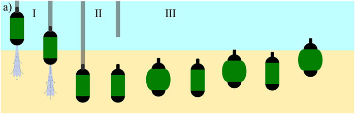
Figure 1. The burrowing and unburrowing mechanisms for the proposed system consisting of three phases: I) Self-burrowing in submerged GM using tethered fluidization. II) Tether detaches when the robot reaches the required depth. III) The robot self-burrows out of GM using periodic volume change.
Our unburrowing mechanism relies on the periodic radial expansion of a soft bladder fabricated with thermoplastic polyurethane (TPU), which, through mechanical interactions with the surrounding GM, generates enough force to push the robot upward. The bladder, shaped like a toroid, was made with TPU sheet of 0.12 mm thickness to resist damage from interactions with GM, and to withstand working pressures of 20–30 PSI; once fabricated, it was assembled over a 3D-printed body (Figure 2).
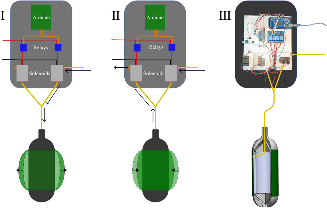
Figure 2. I) The pathway of air during the supply cycle. (The black arrows show the pathway the air takes) II) The pathway of air during the exhaust cycle. (The black arrows show the pathway the air takes) III) The physical pneumatic control board and the connection schematic for the bladder.
In order to explore how the shape of the bladder affects the unburrowing performance of the robot, we tested two variations of the bladder: full-skin and half-skin (Figure 3). The full-skin bladder covered the entire length of the center part of the robot, while the half-skin covered only half the length. Therefore, for the same maximum diameter of the bladder, the half-skin variation would require less fluid volume as compared to the full-skin version. This comparison allowed us to test the competing effects of the volume vs the rate of shape change, as we assumed that a smaller bladder could be inflated more quickly.
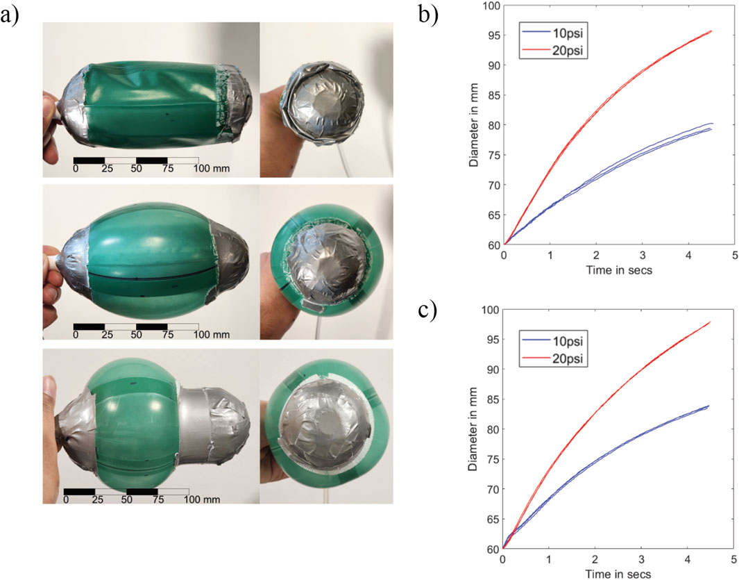
Figure 3. (a) Front and side views of the deflated full-skin variation, inflated full-skin variation bladder, inflated half-skin variation bladder (top to bottom). (b) Diameter vs. time for the full-skin bladder for 10 PSI and 20 PSI. (c) Diameter vs. time for the half-skin bladder for 10 PSI and 20 PSI. The x-axes for both plots are
The radial expansion mechanism was initially controlled by an external control board consisting of a microcontroller (Arduino Mega), solenoid valves (SMC VQ110U) connected to pressure-regulated air supply, and relays (ELEGOO 4 Channel DC 5 V Relay Module); in later iterations, these components were housed within the robot body to achieve untethered operation. To regulate the extent of radial expansion, we controlled the time the bladder was allowed to expand
2.2 Experimental setup for characterizing unburrowing behavior
We first performed unburrowing tests in a dry sand test bed to characterize the unburrowing behavior of the actuator. The reason for initial testing in dry GM, as opposed to submerged GM, is twofold. First, to ensure the repeatability of our data, we fluidized the test bed with air between each experiment to reset the volume fraction of the GM (Gravish et al., 2010). While this process is reliable and widely used for experiments in dry GM, resetting submerged GM is significantly more challenging due to interactions between the water and GM, and such methods are relatively underdeveloped. Second, since we used air to inflate the TPU bladder, we were concerned that the buoyancy effect may influence the results of the experiments by aiding the unburrowing process; therefore, we first tested the mechanism in the worst-case scenario of dry test bed first, then in later demonstration showed that the mechanism also worked in submerged GM.
For the granular substrate, we used glass beads of 0.3 mm diameter to mimic the particle size of medium sand (0.2 mm–0.63 mm according to ISO 14688-1:2017). The dry sand test bed had dimensions of 420 mm × 420 mm wide, with a maximum sand depth of 350 mm, and was integrated with an air-based fluidization system to reset the GM to a uniformly packed state between experiments (Gravish et al., 2010). Before each experimental run, we placed our robot at the bottom of the sand bed while fluidizing the entire test bed. We then turned off the fluidizing bed, started the cyclic radial expansion of the bladder, and recorded the unburrowing performance of the robot from the bottom to the top of the sand bed.
To characterize the behavior and performance of the unburrowing mechanism, we performed a set of three trials with the half-skin variation. The robot in this configuration weighed 200 g. We regulated the supply pressure (connected to the fluidic control board) to 10 PSI. Due to the interactions with the surrounding GM, we assumed that the extent of radial expansion of the bladder at a given internal pressure would be inversely proportional to the depth of the sand in the robot. To track the position of the robot, we attached a long, hollow aluminum tube with a diameter 6 mm to the top of the robot to protrude out of the sand throughout the experiment in order to track the position of the robot as it unburrowed (Figure 5a). After each test, we used a video analysis software (Tracker Version 6.1.6, Open Source Physics) to track the position of the robot over time.
2.3 Experimental setup for characterizing burrowing behavior
We evaluated the effectiveness of our water jet-based fluidization mechanism for burrowing in submerged GM by measuring the self-burrowing rate of an intrusion probe in a test bed (cylinder with diameter 500 mm and maximum submerged GM depth of 550 mm) filled with the same granular substrate used for dry test bed, now submerged in water (Figure 4). The probe consisted of a PVC tube of diameter 60 mm with a nozzle on the bottom end and was connected to a water supply on the top. Two hoops constrained the PVC tube to only allow vertical motion. We used a diaphragm pump to generate flow rates of water around a nominal operating flow of 0.12
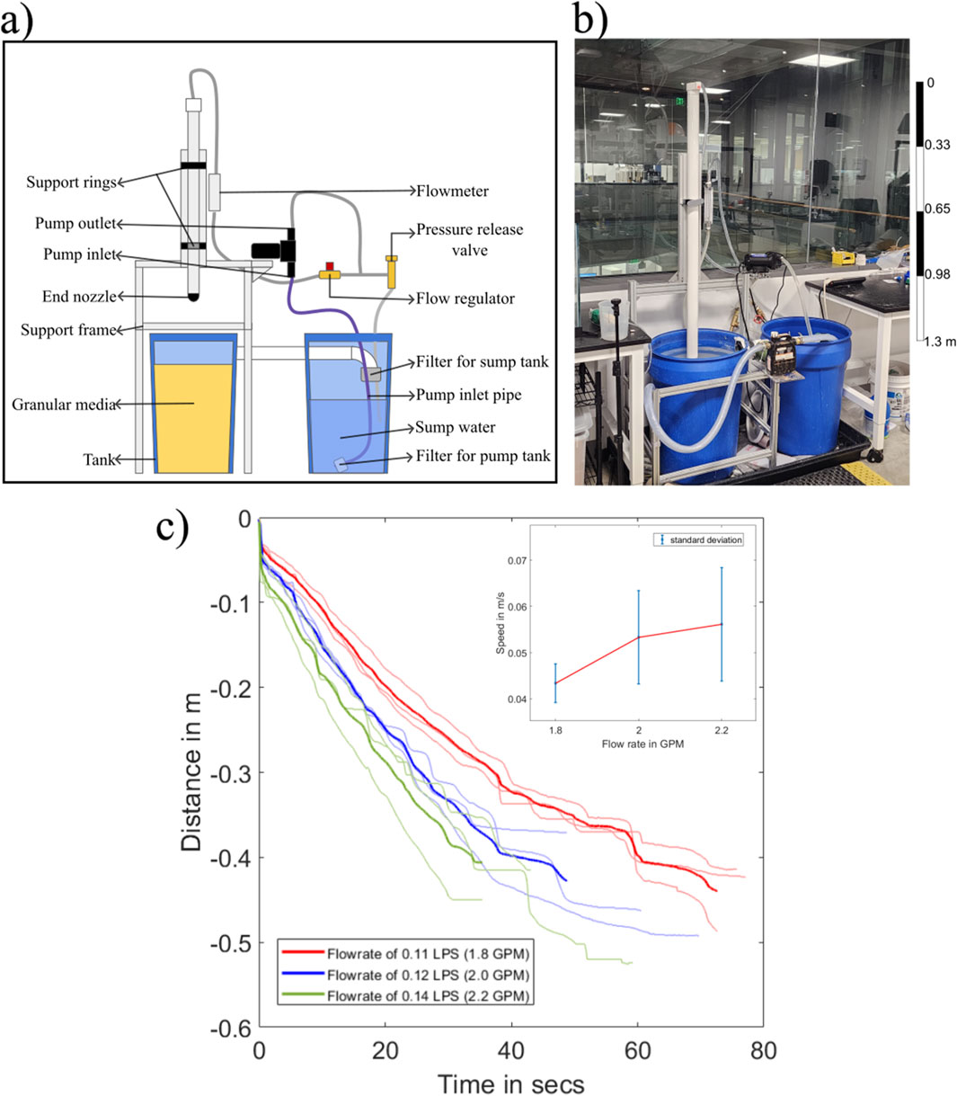
Figure 4. (a) Experimental setup to characterize the relation of self-burrowing rate vs. the flow rate of water. (b) The physical setup used to perform the self-burrowing experiments. (c) Recorded position of probe (in meters) over time (in seconds), which shows the effect of flow rate on the burrowing speed.
As discussed previously, resetting the compaction ratio of submerged GM is more challenging than in dry GM; we initially observed that if the GM was not reset properly after each test, there were pockets of loosely packed GM in the region where the probe had burrowed into, leading to inconsistent results in the subsequent trials. In order to resolve this issue, we used an additional pump connected to a separate nozzle, which was used to stir up and fluidize the entire test bed. Afterward, the submerged GM was allowed to settle down, and we used a heavy plate to apply uniform pressure to the top surface of the GM. Using this process, we noticed increased consistency in the results.
3 Experimental results
3.1 Burrowing performance in submerged granular media (GM) with water-based fluidization
The results of the self-burrowing tests in submerged GM showed that when the flow rate increases, the rate at which the tube self-burrows increases (Figure 4c). We found that all three ranges of flow rate were able to self burrow to a depth of 0.4 m. However, the large variability in the results prevents us from identifying a clear trend in the data.
3.2 Unburrowing performance with the radial expansion mechanism
For the unburrowing tests, we initially set
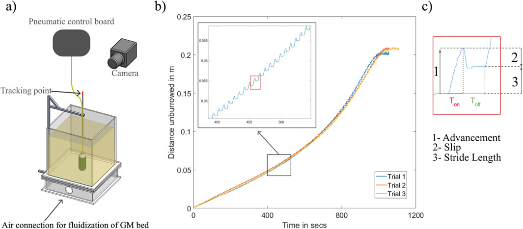
Figure 5. (a) Experimental setup used to measure burrowing-out data. (b) Distance burrowed out vs. Time.
To evaluate the effect of the sand depth on these three components of the unburrowing cycle, we plotted the
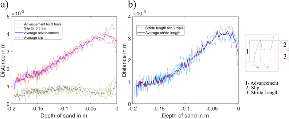
Figure 6. (a)
3.3 Effect of cycle time on the unburrowing performance
Looking at the closeup of the locomotion pattern (Figure 5c), we observed that during the exhaust cycle, the
To test this hypothesis, we performed an additional set of tests, where we reduced
The results showed that reducing the exhaust time decreased the unburrowing time. The robot with the shorter cycle time (7 s) reached the surface after an average time of 780 s compared to 890 s for the original cycle time (8 s; Figure 7a), which corresponds to a 12.5% improvement in the unburrowing time. However, looking at depth vs number of cycles, we also plotted the position of the robot against the number of cycles the bladder has expanded and contracted. Since the total cycle time (i.e.,
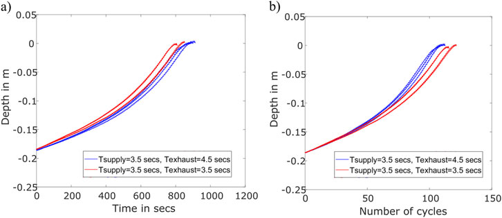
Figure 7. Measuring the effect of bladder deflation time on unburrowing speed and efficiency. (a) Depth unburrowed (in meters) vs. time required (in seconds). (b) Depth unburrowed (in meters) vs. Number of cycles required.
3.4 Effects of the varying weight of the robot and the shape of the bladder on the unburrowing performance
To understand how the unburrowing performance of the robot was affected by the shape of the bladder and the intrinsic weight of the robot, we performed additional unburrowing experiments in the dry GM test bed. For each configuration, we conducted three trials each with varying
The first set of experiments was performed without adding extra weight to the robot, which, in this configuration weighed 200 g. We observed that the full-skin variation, on average, unburrowed 21% faster than the half-skin variation (Figure 8a). For both variations, the unburrowing performance remained consistent for all
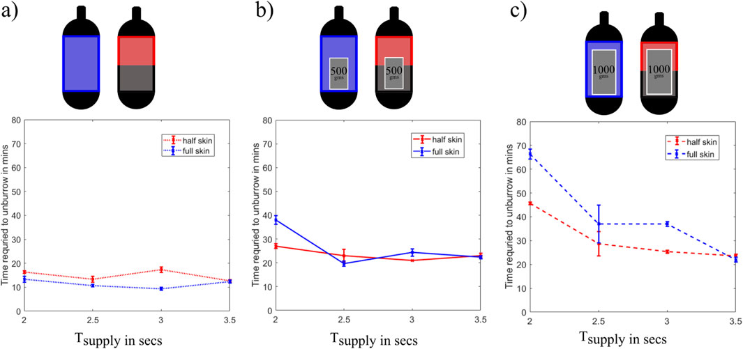
Figure 8. (a) Time required to unburrow in minutes vs. Supply time in seconds for a robot just burrowing out without any extra weight. (b) Time required to unburrow in minutes vs. Supply time in seconds for a robot burrowing out with an extra 500-g weight in the internal cavity. (c) Time required to unburrow in minutes vs. Supply time in seconds for a robot burrowing out with an extra 1,000-g weight in the internal cavity.
To observe how the weight of the robot affects its burrowing-out performance, we then conducted the same tests after adding a 500-g weight to the internal cavity of the 3D-printed core of the robot (i.e., total weight was 700 g). In this configuration, the half-skin variation burrowed out 29% faster than the full-skin variation for
Finally, we also conducted experiments after adding a 1,000-g weight to the robot, which increased the total weight to 1,200 g. For this configuration, we observed that the half-skin variation burrowed-out faster than the whole-skin variation for most of the
4 Demonstration of a robot capable of burrowing using water jet and untethered self-unburrowing using cyclical radial expansion
So far, we have characterized the two main parts of our proposed method—burrowing using water jet-based fluidization and unburrowing using cyclical radial expansion of the bladder. In this section, we design and test a robot that combines both of these functionalities, using a tether to burrow into submerged GM, detaching, and burrowing out untethered. We examined two approaches to achieve untethered unburrowing: embedding a CO2 canister to supply gas for shape change, and using a gear pump and an internal liquid bladder.
4.1 Burrowing out using an onboard gas supply from a CO2 canister
4.1.1 Design and fabrication
We designed a pneumatic system using a pressurized 45 g CO2 canister as our air supply (Figure 9a). We regulated the pressure from the
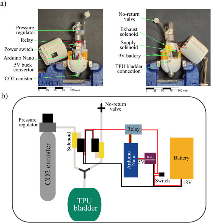
Figure 9. Design of an untethered shape change unburrowing system with an onboard supply of
4.1.2 Operation and design limitations
For the untethered unburrowing tests using
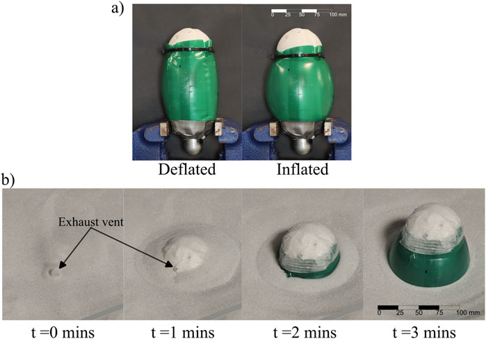
Figure 10. Experimental testing of the
We tested the ability of the
4.2 Water pump-based hydraulic untethered unburrowing approach
In order to overcome the limitations of the
4.2.1 Design and fabrication
In this final approach, we constructed a robot that was 21.5 cm in length and 7 cm in diameter that is capable of fluidization burrowing and untethered unburrowing. Instead of using a compressed
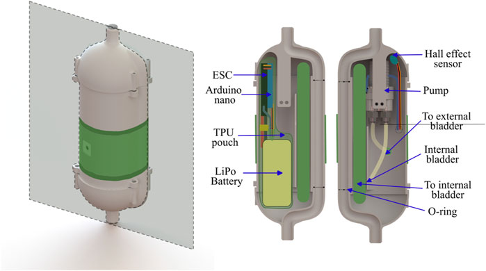
Figure 11. 3D CAD rendering of the water robot with shape change actuated by a water pump, with the cross-section plane (Left). The cross-section of the inside of the robot with primary components labeled (Right).
In addition, we also integrated the tethered water jet-based self-burrowing capability to this version of the robot. The water tether was initially attached to the top of the robot, and was detached when the robot had burrowed to its final depth of 9 inches (measured from between the top of the robot and the top surface of the sand). An internal channel in the 3D-printed body of the robot wrapped around the mechatronic components, directing the water flow to the nozzle at the bottom of the robot. A magnet attached to the end of the tether, along with a hall effect sensor within the robot, acted as a switch for the unburrowing mechanism; the unburrowing process began automatically when the robot had sensed that the tether was detached. The pump and the hall effect sensor were IP67 water-resistant and did not require waterproofing, but all other electronics were sealed within a TPU pouch (Figure 12).
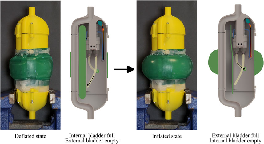
Figure 12. Water pump actuation of the shape change of the prototype robot. Left: Photograph and cross-sectional CAD schematic of the robot in the deflated state; the cross-section shows the full internal bladder. Right: Photograph and cross-sectional CAD schematic of the robot in the inflated state; the cross-section shows the empty internal bladder.
4.2.2 Operation and design limitations
In this system, the pump took 8 s to pump water from the internal bladder to the external bladder and another 8 s from the external bladder to the internal bladder. With the installed 1,300 mAh battery, the pump could operate around 50 min, which corresponded to 188 cycles with the cycle time of 16 s. This is three times as many cycles compared to the
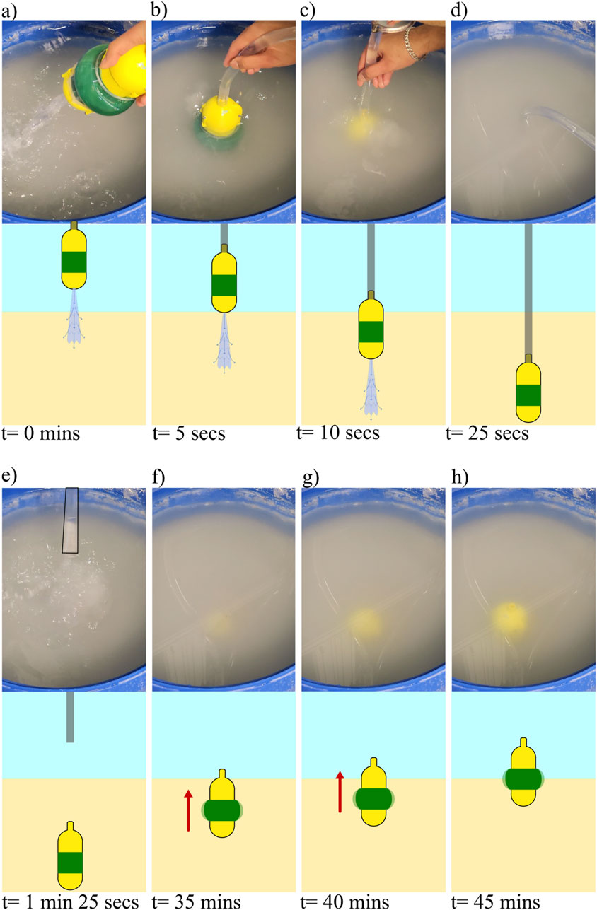
Figure 13. Demonstration of integrated system capable of water jet based burrowing, and untethered unburrowing via shape change. (a–h) Images from a video of the burrowing/unburrowing test (top) with corresponding schematics of the state of the robot in the GM (bottom) at the following steps of the process: (a) robot above the submerged GM with water flow turned on, (b) robot touching the submerged GM, (c) robot below the surface of the water and entering the surface of the GM, (d) robot at a depth of 230 mm below the surface of the GM, water flow is turned off, (e) tether pulled off after a rest period of 1 min, (f) the robot emerges above the surface of the GM after 33.5 min, (g) picture of the robot after 38.5 min, (h) Picture of the robot after reaching the top after 43.5 min.
5 Conclusion
In this paper, we present a bio-inspired robot capable of both burrowing into, and without the aid of a tether, burrowing out out of submerged granular media (GM). The system uses a tethered water-jet-based approach for fluidization-based self-burrowing in submerged GM, and we have shown that the larger the flow rate of the jet, the greater the drag reduction and the faster the self-burrowing. For unburrowing, we demonstrate an untethered soft volume-change-based mechanism that uses periodic radial expansion to burrow out of both dry and submerged GM. We showed that for the unburrowing mechanism at a given activation pressure, the
Potential applications of this work range from long-term environmental monitoring in sensitive marine ecosystems to underwater archaeology. Future work could investigate different bladder shapes to increase unburrowing performance in GM. In addition, the effects of varying nozzle diameters or the effects of having multiple nozzles on the burrowing performance could be studied. Also, onboard pumping methods for fluidization could be studied to make the system completely untethered.
Data availability statement
The raw data supporting the conclusions of this article will be made available by the authors, without undue reservation.
Author contributions
AN: Data curation, Formal Analysis, Writing – original draft, Writing – review and editing. HS: Conceptualization, Writing – original draft. NG: Supervision, Writing – original draft, Writing – review and editing. MT: Supervision, Writing – original draft, Writing – review and editing.
Funding
The author(s) declare that financial support was received for the research and/or publication of this article. This material is based upon work supported by the Office of Naval Research under grant number N00014-20-1-2373, N00014-23-1-2169, and N00014-23-1-2358.
Acknowledgments
The authors would like to give special thanks to Iman Adibnazari, whose assistance has been indispensable. We would also like to thank the lab members in the Bioinspired Robotics and Design Lab and Gravish Lab. Their camaraderie, collaboration, and insightful discussions have created a stimulating and supportive environment that has been crucial to the development of this project.
Conflict of interest
The authors declare that the research was conducted in the absence of any commercial or financial relationships that could be construed as a potential conflict of interest.
Generative AI statement
The author(s) declare that no Generative AI was used in the creation of this manuscript.
Publisher’s note
All claims expressed in this article are solely those of the authors and do not necessarily represent those of their affiliated organizations, or those of the publisher, the editors and the reviewers. Any product that may be evaluated in this article, or claim that may be made by its manufacturer, is not guaranteed or endorsed by the publisher.
Supplementary material
The Supplementary Material for this article can be found online at: https://www.frontiersin.org/articles/10.3389/frobt.2025.1546407/full#supplementary-material
References
Bagheri, H., Stockwell, D., Bethke, B., Kwame, N., Aukes, D., Tao, J., et al. (2023). A bio-inspired helically driven self-burrowing robot. Acta Geotech. 19, 1435–1448. doi:10.1007/s11440-023-01882-9
Chopra, S., Vasile, D., Jadhav, S., Tolley, M., and Gravish, N. (2023). Toward robotic sensing and swimming in granular environments using underactuated appendages. Adv. Intell. Syst. 5, 2200404. doi:10.1002/aisy.202200404
Clark, L., Whalley, R., and Barraclough, P. (2003). Roots: the dynamic interface between plants and the earth. Plant Soil 255, 93–104. doi:10.1023/A:1026140122848
Cui, Z., Li, L., Wang, Y., Zhong, Z., and Li, J. (2023). Review of research and control technology of underwater bionic robots. Intelligent Mar. Technol. Syst. 1, 7. doi:10.1007/s44295-023-00010-3
Ding, Y., Gravish, N., and Goldman, D. I. (2011). Drag induced lift in granular media. Phys. Rev. Lett. 106, 028001. doi:10.1103/physrevlett.106.028001
Dorgan, K. (2015). The biomechanics of burrowing and boring. J. Exp. Biol. 218, 176–183. doi:10.1242/jeb.086983
Drotman, D., Chopra, S., Gravish, N., and Tolley, M. (2022). Anisotropic forces for a worm-inspired digging robot. in 2022 IEEE 5th International Conference on Soft Robotics (RoboSoft). Edinburgh, United Kingdom, 04-08 April 2022 (IEEE), 261–266. doi:10.1109/RoboSoft54090.2022.9762155
Dunbabin, M., and Marques, L. (2012). Robots for environmental monitoring: significant advancements and applications. IEEE Robot. Autom. Mag. 19, 24–39. doi:10.1109/MRA.2011.2181683
Evangelista, D., Hotton, S., and Dumais, J. (2011). The mechanics of explosive dispersal and self-burial in the seeds of the filaree, erodium cicutarium (geraniaceae). J. Exp. Biol. 214, 521–529. doi:10.1242/jeb.050567
Germann, D., and Carbajal, J. (2013). Burrowing behaviour of robotic bivalves with synthetic morphologies. Bioinspiration Biomimetics 8, 046009. doi:10.1088/1748-3182/8/4/046009
Gravish, N., Umbanhowar, P. B., and Goldman, D. I. (2010). Force and flow transition in plowed granular media. Phys. Rev. Lett. 105, 128301. doi:10.1103/physrevlett.105.128301
Gyeol, H., Seo, D., Ryu, J.-H., and Kwon, T.-H. (2023). Rootbot: root-inspired soft-growing robot for high-curvature directional excavation. Acta Geotech. 19, 1–13. doi:10.1007/s11440-023-02073-2
Huang, S., and Tao, J. (2022). Bioinspired horizontal self-burrowing robot, 223–231. doi:10.1061/9780784484036.023
Isaka, K., Tsumura, K., Watanabe, T., Toyama, W., Sugesawa, M., Yamada, Y., et al. (2019). Development of underwater drilling robot based on earthworm locomotion. IEEE Access 7, 103127–103141. doi:10.1109/ACCESS.2019.2930994
Kim, S., Treers, L. K., Huh, T. M., and Stuart, H. S. (2023). Efficient reciprocating burrowing with anisotropic origami feet. Front. Robotics AI 10, 1214160. doi:10.3389/frobt.2023.1214160
Macdonald, I. (2015). “Burial mechanics of the Pacific sandfish: the role of the ventilatory pump and physical constraints on the behavior,”. Master’s thesis (Flagstaff, AZ: Northern Arizona University).
Maladen, R., Ding, Y., Li, C., and Goldman, D. (2009). Undulatory swimming in sand: subsurface locomotion of the sandfish lizard. Sci. (New York, N.Y.) 325, 314–318. doi:10.1126/science.1172490
Maladen, R., Ding, Y., Umbanhowar, P., and Goldman, D. (2011). Undulatory swimming in sand: experimental and simulation studies of a robotic sandfish. Int. J. Robotics Res. 30, 793–805. doi:10.1177/0278364911402406
Martinez, A., DeJong, J., Akin, I., Aleali, A., Arson, C., Atkinson, J., et al. (2021). Bio-inspired geotechnical engineering: principles, current work, opportunities and challenges. Géotechnique 72, 687–705. doi:10.1680/jgeot.20.P.170
Montana, J., Finn, J., and Norman, M. (2015). Liquid sand burrowing and mucus utilisation as novel adaptations to a structurally-simple environment in octopus kaurna stranks, 1990. Behaviour 152, 1871–1881. doi:10.1163/1568539X-00003313
Naclerio, N., Karsai, A., Murray-Cooper, M., Ozkan Aydin, Y., Aydin, E., Goldman, D., et al. (2021). Controlling subterranean forces enables a fast, steerable, burrowing soft robot. Sci. Robotics 6, eabe2922. doi:10.1126/scirobotics.abe2922
Naziri, S., Ridgeway, C., Castelo, J., Ibarra, S., Provenghi, K., and Cortes, D. (2024). Earthworm-inspired subsurface penetration probe for landed planetary exploration. Acta Geotech. 19, 1267–1274. doi:10.1007/s11440-024-02240-z
Omori, H., Nakamura, T., and Yada, T. (2009). An underground explorer robot based on peristaltic crawling of earthworms. Industrial Robot-an Int. J. 36, 358–364. doi:10.1108/01439910910957129
Ortiz, D., Gravish, N., and Tolley, M. (2019). Soft robot actuation strategies for locomotion in granular substrates. IEEE Robotics Automation Lett. 4, 2630–2636. doi:10.1109/LRA.2019.2911844
Sadeghi, A., Mondini, A., and Mazzolai, B. (2017). Toward self-growing soft robots inspired by plant roots and based on additive manufacturing technologies. Soft Robot. 4, 211–223. doi:10.1089/soro.2016.0080
Tao, J., Huang, S., and Tang, Y. (2020). Sbor: a minimalistic soft self-burrowing-out robot inspired by razor clams. Bioinspiration Biomimetics 15, 055003. doi:10.1088/1748-3190/ab8754
Treers, L., McInroe, B., Full, R., and Stuart, H. (2022). Mole crab-inspired vertical self-burrowing. Front. Robotics AI 9, 999392. doi:10.3389/frobt.2022.999392
Trueman, E. (1967). The dynamics of burrowing in Ensis (Bibalvia). Proc. R. Soc. Lond. B Biol Sci 166, 459–476. doi:10.1098/rspb.1967.0007
Trueman, E. (1970). The mechanism of burrowing of the mole crab, emerita. J. Exp. Biol. 53, 701–710. doi:10.1242/jeb.53.3.701
Weiwei, Z., li, L., Jiang, S., Ji, J., and Deng, Z. (2019). Inchworm drilling system for planetary subsurface exploration. IEEE/ASME Trans. Mechatronics 25, 837–847. doi:10.1109/TMECH.2019.2962500
Winter, A., Deits, R., Dorsch, D., Slocum, A., and Hosoi, A. (2014). Razor clam to roboclam: burrowing drag reduction mechanisms and their robotic adaptation. Bioinspiration Biomimetics 9, 036009. doi:10.1088/1748-3182/9/3/036009
Keywords: soft robot, burrowing, granular media, shape change, fluidization, untethered
Citation: Nayak A, Seo H, Gravish N and Tolley MT (2025) Burrowing and unburrowing in submerged granular media through fluidization and shape-change. Front. Robot. AI 12:1546407. doi: 10.3389/frobt.2025.1546407
Received: 16 December 2024; Accepted: 30 June 2025;
Published: 31 July 2025.
Edited by:
Yasemin Ozkan-Aydin, University of Notre Dame, United StatesReviewed by:
Saravana Prashanth Murali Babu, University of Southern Denmark, DenmarkMahdi Haghshenas-Jaryani, New Mexico State University, United States
Qiyuan Fu, Biorobotics Laboratory (BioRob), Switzerland
Copyright © 2025 Nayak, Seo, Gravish and Tolley. This is an open-access article distributed under the terms of the Creative Commons Attribution License (CC BY). The use, distribution or reproduction in other forums is permitted, provided the original author(s) and the copyright owner(s) are credited and that the original publication in this journal is cited, in accordance with accepted academic practice. No use, distribution or reproduction is permitted which does not comply with these terms.
*Correspondence: Michael T. Tolley, dG9sbGV5QHVjc2QuZWR1; Nick Gravish, bmdyYXZpc2hAdWNzZC5lZHU=