 Nikolay Popov
 Jan P. F. Lagerwall
- Experimental Soft Matter Physics Group, Department of Physics and Materials Science, University of Luxembourg, Luxembourg City, Grand Duchy of Luxembourg
The combination of anisotropic boundary conditions and topological constraints acting on a spherical shell of nematic liquid crystal confined between aqueous phases gives rise to peculiar but well-defined configurations of the director field, and thus of the optic axis that defines the impact of the nematic birefringence. While the resulting optics of nematic shells has been extensively investigated in transmission, studies of the reflection behavior are scarce. Here we show that nematic shells exhibit specific light guiding paths mediated by birefringence-modulated total internal reflection (TIR) within the shell. With stabilizers promoting tangential boundary conditions, shells show immobile antipodal spots revealing the locations of maximum effective refractive index, but their intensity is modulated by the polarization of the illuminating light. With normal-aligning stabilizers, shells instead show bright arcs separated by dark spots, and these follow the rotation of the polarization of the illuminating light. Reflection polarizing microscopy thus offers a valuable complement to the more common characterization in transmission, adding data that can be helpful for accurately mapping out director fields in shells of any liquid crystal phase. Moreover, the TIR-mediated light guiding paths may offer interesting handles to localize photopolymerization of reactive liquid crystal shells or to dynamically modulate the response of light-triggered liquid crystal elastomer shell actuators.
1 Introduction
Since their first practical realization 15 years ago (Fernandez-Nieves et al. (2007)), liquid crystal shells—self-closing spherical layers of liquid crystal surrounding an immiscible isotropic liquid droplet and suspended in a continuous phase of immiscible isotropic liquid—have bloomed into a fertile platform for basic physics research (Lopez-Leon and Fernandez-Nieves (2011); Urbanski et al. (2017)) as well as for several applied avenues (Schwartz et al. (2018, 2021); Chen et al. (2021)). Experiments on nematic shells have revealed a wealth of fascinating phenomena dictated by the topological constraints (Fernandez-Nieves et al. (2007); Lopez-Leon et al. (2011b)) and the temperature-dependent anisotropy of nematic elasticity (Liang et al. (2011b); Lopez-Leon et al. (2011a); Liang et al. (2013); Durey et al. (2020)). By selecting different interface stabilizers, varying boundary conditions can be imposed, giving a convenient handle for tuning the topological constraints (Lopez-Leon and Fernandez-Nieves (2009); Noh et al. (2016b); Sharma and Lagerwall (2018)), even dynamically and reversibly using stabilizers that are temperature- (Sharma et al. (2019); Noh et al. (2020)) or light-responsive (Noh et al. (2018)). Further tuning can be accomplished by applying magnetic (Ishii et al. (2020)) or electric (Gollapelli and Vallamkondu (2019)) fields over the shells. The rich experimental data have in turn stimulated a range of theoretical and simulation works to explain the observed phenomena as well as to predict new ones (Skacej and Zannoni (2008); Bates et al. (2010); Kralj et al. (2011); Mirantsev et al. (2012); Napoli and Vergori (2012); Koning et al. (2013, 2016); Napoli and Vergori (2021)). After demonstrating that the lifetime of shells can be extended by polymer stabilization (Noh et al. (2016a); Geng et al. (2016a)) or complete polymerization (Fleischmann et al. (2012); Jampani et al. (2018, 2019); Geng et al. (2021); Sharma et al. (2021)), applications of nematic liquid crystal shells became viable, for instance as exotic sphere-shaped soft liquid crystal elastomer actuators (Fleischmann et al. (2012); Jampani et al. (2018, 2019)), where the actuation pattern can be templated by topological defects (Sharma et al. (2021)), or for sensing of biologically active molecules such as lipids (Sharma et al. (2022)). Most efforts to apply liquid crystal shells have, however, utilized cholesteric liquid crystals with short enough pitch to exhibit selective Bragg reflection, since the resulting unique optical properties (Geng et al. (2016a); Lee et al. (2017); Geng et al. (2018); Park et al. (2020)) open for innovative applications across diverse areas, from sensing (Kim and Park (2017); Myung and Park (2019)), lasing (Uchida et al. (2013); Iwai et al. (2020)), realization of microactuators (Zhang et al. (2021)) and amplifying photonic upconversion (Kang et al. (2017)) to anti-counterfeiting (Geng et al. (2016a); Schwartz et al. (2018); Arenas et al. (2022)) and assisting robots and Augmented Reality devices in interpreting their surroundings (Schwartz et al. (2018); Geng et al. (2021); Schwartz et al. (2021)).
Central to all research and applications of liquid crystal shells is a detailed and accurate characterization of the director field within each shell, which determines all aspects of the shell behavior. This applies in particular to the optical behavior since the director is also the optic axis of a nematic phase, light experiencing the maximum refractive index n‖ if it is polarized along the director (extraordinary ray), or the minimum refractive index n⊥ for the perpendicular polarization (ordinary ray). The relationship is reversed for optically negative liquid crystals, but the liquid crystal studied in this paper is optically positive, which is the most common case. The method of choice for doing such a characterization is polarized optical microscopy (POM), since the shell textures observed using POM can be highly revealing of the director field. For non-chiral nematic liquid crystal shells, POM is generally used exclusively in transmission mode, since the nematic exhibits no peculiar reflection properties like Bragg reflection. The situation is the opposite for cholesteric shells which are mostly characterized in reflection since Bragg reflection is their key feature, although their behavior in transmission has also been analyzed (Geng et al. (2016b)).
In this paper we leave the conventional paradigm for studying nematic shells and focus on their behavior in reflection. It turns out that the shells show non-trivial effects also in this configuration, with some captivating features arising from the birefringence of the nematic phase in relation to the surrounding isotropic phases. The spatial modulation of the optic axis within the shell, determined by the topological constraints on the director field, leads to a reflection behavior that is highly sensitive to the polarization of the incoming light and, in case of tangential-aligned shells, the location within the shell. When the light is polarized as to experience mainly the greater refractive index n‖, the refractive index contrast to the surrounding phases is large enough that total internal reflection (TIR) occurs along a path around the entire shell, guiding the light back to the observer, but this is not the case when light experiences the smaller n⊥. By analyzing the reflection behavior, a more complete picture of the director field within the shell arises, since the features in reflection are complementary to those in transmission, allowing more accurate characterization. The phenomenon can also be important for all applied avenues relying on photopolymerized shells, since the UV irradiation that triggers polymerization can have very different impact along paths with and without light guiding, as well as for optical applications like lasing where the light guiding may add undesired effects.
2 Materials and methods
2.1 Materials
Poly (vinyl alcohol) PVA (Sigma-Aldrich,
2.2 Shell production
Liquid crystal shells containing and surrounded by aqueous phases of PVA or Tween-20 solutions were produced by using a coaxial glass capillary microfluidic setup, as described by Weitz and co-workers (Utada et al. (2005)). The inner aqueous solution, immiscible with the middle phase (E7), was flown through a tapered cylindrical capillary (inlet) with a 65 μm diameter orifice, injected into the liquid crystal that was flowing in the same direction within a square cross section capillary in which the inlet had been inserted. The continuous phase, consisting of the same aqueous solution as used for the inner phase, flowed in the opposite direction through the same square cross section capillary. By keeping all flow rates low enough, the compound E7–inner phase flow detached near the inlet without jetting (dripping mode) into shells carried by the continuous phase. The three-phase flow was flow-focused into the outlet capillary (inner diameter 170 μm).
The E7 shells were produced at isotropic state at 65°C by keeping the coaxial capillary setup on a tailor-made hot stage. All liquids were kept in closed vials that were pressurized with high accuracy by a Fluigent MFCS-EZ pneumatic flow control unit, inducing flow at controlled speed through flexible microfluidic tubing leading from the vials to the coaxial capillary set-up. The shells were collected in rectangular capillaries, the ends of which were sealed by epoxy glue to avoid evaporation of water. For observation and analysis using microscope each capillary containing shells was placed in a Linkam T95-PE hot stage mounted on a Nikon Eclipse LV100ND POM. For storage between experiments, shells were kept at 30°C in an incubator.
2.3 Shell characterization
Figure 1 illustrates the experimental characterization geometries. Because the density of E7 at the temperature where we conducted the experiments (39 °C) is greater than that of our aqueous PVA solution at the same temperature, the inner droplet rises to the top of the shell, rendering the shell top the thinnest point and the shell bottom the thickest point. All our experiments are carried out with polarized light, originating from below the shell in the transmission configuration of the POM (Figure 1A) or from a reflection light source that sends the light through the objective, illustrated in a “side-by-side” fashion in Figure 1B. Both polarizers, in reflection and transmission mode, can be continuously rotated. A rotatable analyzer is placed above the sample before the camera used for capturing videos and photos. When desired, a first-order λ-plate (530 nm) was inserted in the observation light path, prior to the analyzer.
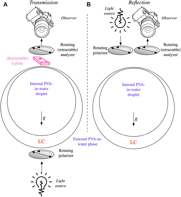
FIGURE 1. Schematic of the observation geometries used in the study, in transmission (A) and in reflection (B). Note that the reflection configuration of the microscope couples the light through the objective, which thus acts as condenser and objective at the same time, and the final illumination path is thus coaxial with the observation direction; the side-by-side drawing is only for illustration purposes, to highlight that a separate rotatable polarizer is present also in reflection. All shells have a liquid crystal phase that is denser than the surrounding aqueous solutions, hence the shells are thinnest at the top and thickest at the bottom.
3 Results
The expected director fields for our two types of shell are sketched in the simplest possible way in Figure 2. If tangential boundary conditions prevail, in our case achieved by using PVA as stabilizer, the spherical topology requires the director field to comprise a total topological defect charge of +2 across the shell circumference (Lopez-Leon and Fernandez-Nieves (2009); Urbanski et al. (2017)), as dictated by the Poincaré–Hopf theorem. In order to minimize the total free energy, integrated over interfaces and bulk, the nematic generally locates all defects near the thinnest point of the shell (Fernandez-Nieves et al. (2007)), although several ways of distributing the total +2 defect charge are possible. Because of density mismatch between the liquid crystal and the inner isotropic phase, shells are usually asymmetric, gravity driving the inner droplet either down or up within the liquid crystal shell, depending on the sign of density mismatch. The higher the asymmetry, i.e., the thinner the shell is at its thinnest point (and the thicker it is at the antipode), the closer the defects are to the thinnest point and the more likely it is that two +1/2 defects merge into one +1 defect or even that two +1 defects merge into a single +2 defect, thus being the sole defect within the shell (Lopez-Leon et al. (2011b)).
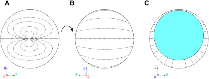
FIGURE 2. (A,B) Sketches of the outside director field projection onto the image plane for the tangentially aligned shells studied here, with a very thin top and rather thick bottom, seen from the top (A) and from the bottom (B). (C) For the radially aligned shells, we sketch the director field in the cross section of the shell. Gravity is directed along the negative
We previously found Sharma et al. (2022) that shells with relatively high average thickness, as in this study, tend to have very strong asymmetry, and the defect or defects are then very close to the thinnest point of the shell. Indeed, throughout this study, tangential-aligned shells have a texture that corresponds to the director field in Figures 2A,B, which has a single +2 defect at the thinnest point (a) and a rather uniform director field throughout the thick side (b). By investigating high-magnification POM images of our shells (Figure 3) we can see that our shells actually come in two forms, either with two +1 defects (a/e and b/f) or with four +1/2 defects (c/g and d/h). However, in all cases the defects are so close to each other that the texture is nearly identical to that of a single +2 defect, and outside the defect region the director field is identical to that of a shell with a single +2 defect at the thinnest point. For this reason, and because the single +2 defect director field is slightly easier to draw and analyze, we use this as an approximation of the director field within the shells in the following, which is perfectly adequate for all types of analysis in this paper.
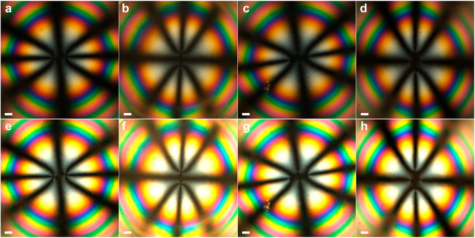
FIGURE 3. High-magnification transmission POM images of tangential-aligned nematic E7 shells, zooming in on the thinnest region where the defects are collected. The upper (as A, B, C, D) row shows the original photos while the lower (as E, F, G, H) shows digitally enhanced versions of the same photos, optimized for revealing the defects. We find shells with two +1 defects (a/e and b/f) and four +1/2 defects (c/g and d/h). Scale bar (thick white line) is 10 μm.
In case of radial boundary conditions, imposed here by using the surfactant Tween-20 as stabilizer, we get a defect-free director field as sketched in Figure 2C, now depicting a vertical cross section through the shell rather than a projection of the top or bottom. While a nematic droplet would have to have a +1 bulk defect at its core, the presence of the isotropic liquid droplet at the shell interior removes this requirement for the liquid crystal shell.
3.1 Tangential-aligned shells observed in transmission and reflection
Figure 4 shows a set of tangential-aligned nematic E7 shells. Panels a) and b) show the transmission texture between crossed polarizers, without and with, respectively, a first-order λ-plate inserted. Every shell carries a characteristic 8-brush pattern that reflects the director field sketched in Figure 2A, particularly clear when the x-axis, as defined in Figure 2, is parallel or perpendicular to the polarizer (or analyzer). This pattern is well known in the community and its general origin is easily derived by mapping out the impact of birefringence when the optic axis is modulated as shown in Figure 2A (Fernandez-Nieves et al. (2007)). The fact that each shell appears extended along the x-axis is an optical artifact related to the different lensing effects for light experiencing n⊥ or n‖, as we recently explained (Noh et al. (2020)). The insertion of the λ-plate allows the director field to be confirmed with respect to the 90° ambiguity concerning the optic axis orientation that always results when studying a birefringent material in POM, hence we can draw the director field of each shell (sketching only the top halves) as in Figure 4D.
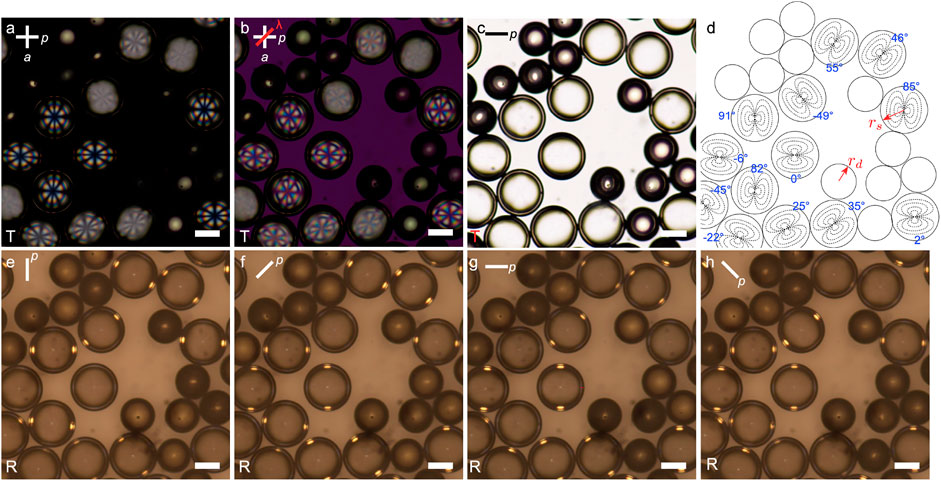
FIGURE 4. A set of thin-topped tangentially aligned E7 shells (radius rs) and droplets (radius rd), the latter originating from shells that broke, at 39°C observed in transmission (T) between crossed polarizers (A), with a λ-plate (slow axis indicated with red line) inserted in (B), and in transmission without analyzer (C). The orientations of polarizer (p) and analyzer (a, when present) are indicated with white lines. The drawing in (D) of the shell and droplet contours, with the shell director fields sketched, is qualitatively established from the appearance in (A) and (B), whereas the quantitative orientation of each shell (indicated with blue text; the angle is that between the polarizer axis and the
We note, however, that every shell that is oriented with its x-axis significantly away from the polarizer and analyzer directions appears with much lower contrast and with a grey-white appearance. This is because both the ordinary and extraordinary modes are excited within the thick side of each of these shells when light enters. In most work the operator carefully rotates the sample such that the back side has its director either parallel or perpendicular to the light polarization, in order that this side gives no contribution to the effective birefringence effects, allowing an easy correlation between the observed texture and the director field on the thin side. Since here we show a multitude of shells next to each other, without control of how each shell is oriented around the gravity axis, such selection is impossible, and we thus see shells with textures given solely by their thin-side director field as well as shells where the thick side impacts the result. The full analysis is beyond the scope of this paper, but we should expect significant splitting of the light rays entering the shell to take place, in combination with lensing effects due to the shell curvature which are different for the ordinary and extraordinary rays, in addition to an optical path difference of several orders being introduced, given the high value of Δn = n‖ − n⊥ for E7. The impact will be greater the thicker the shell at its thickest side, hence the blurry texture suggests that the shells are rather thick here.
We also note that the imaged area contains several nematic droplets in addition to the shells. These originated from shells which broke during the sample preparation procedure. Utilizing this knowledge, the droplets are actually useful for us, as they allow us to calculate the average shell thickness as follow. We know that the volume of each droplet is the volume of liquid crystal inside a single shell. We can measure the shell radius rs ≈ 97 μm and droplet radius rd ≈ 72 μm from the micrographs in Figure 4. This allows us to calculate the volumes:
and
of a single droplet and a single shell, respectively. The difference Vi = Vs − Vd must be equal to the volume of the internal (i) water droplet residing inside each shell. Having access to this, we can, in turn, calculate the radius ri of the inner water droplet as:
We can now calculate the average shell thickness as
The reflection behavior of the shells (and droplets) is shown in panels (e) to (h), the polarization of the illuminating light changing stepwise by 45° from panel to panel, as indicated at the top left with a white line. Note that these images are obtained without analyzer. We see that each shell exhibits two bright spots near the shell perimeter, where this intersects with the y-axis of the shell, provided that the illuminating light is not also polarized along this axis. If the polarization is oriented along this axis, the spots disappear, and the overall shell perimeter looks dark. Supplementary Movie S1 shows the reflection behavior upon continuous rotation of the polarizer, showing that the disappearance of the spots is quite sharply located around the polarization direction along the y-axis of the shell. The behavior is identical for all shells. Comparing panels (c) and (g), both obtained without analyzer and with horizontal polarizer, but (c) in transmission and (g) in reflection, we see that the isolated shell slightly below and to the left of the center exhibits two antipodal darkest arcs along the top and bottom in the transmission image, and that the centers of these arcs coincide with the brightest spots in the same shell observed in reflection. In passing, we note that also the droplets show varying reflection (and transmission) intensity depending on light polarization, but a full analysis of the droplet behavior is outside the scope of this paper.
The spots are so well localized in each shell that it is by measuring the rotation of the axis separating the spots that we can establish the accurate angular values in Figure 4D that describe the orientation of each shell around the gravitational axis. Especially for the shells that have the x-axis oriented neither parallel nor perpendicular to the polarizer it is nearly impossible to analyze the texture accurately in transmission mode, due to the strong scattering originating from the birefringence of the thick side. In reflection, however, all shells are imaged equally well, regardless of their orientation.
Several shells have small irregularly placed dark spots. These are most likely due to contaminating dust particles; all liquids were filtered prior to shell preparation but the filter lets through particles up to 1.2 μm diameter. Since the long-range order of the nematic can amplify the visual impact of small disturbances, even such small particles may give rise to scattering, leading to the dark spots.
3.2 Radial-aligned shells observed in transmission and reflection
The POM characterization of the corresponding shells with radial director alignment (as in Figure 2C), achieved by stabilizing them with Tween-20 surfactant, are shown in Figure 5. In transmission between crossed polarizers (a), each shell exhibits a characteristic texture with a cross and multiple concentric rings, very much resembling a conoscopy texture of a homeotropically aligned flat nematic sample. Enz et al. explained that this is because the effective optics are equivalent for these two situations (Liang et al. (2011a)), the conoscopy probing all illumination directions around a uniform director field, the radial-aligned shells in regular orthoscopic POM probing all director field orientations with unidirectional illumination. Switching to reflection while maintaining the crossed polarizer configuration (b), the texture is dominated by a bright perimeter that is interrupted at the top and bottom and left and right extremes, thus along the cross sections with the polarizer and analyzer directions, respectively. This very much resembles the reflection behavior between crossed linear polarizers of tangential-aligned shells of short-pitch cholesteric analyzed by Geng et al. (Geng et al. (2018)); the resemblance is not surprising since the effective optic axis of a short-pitch cholesteric is along the helix. Thus those shells, just like the ones in Figure 5, had radially aligned optic axis. Geng et al. described the effect as a result of total internal reflection within the shell, and we will see below that this holds also for the radial-aligned nematic shells.
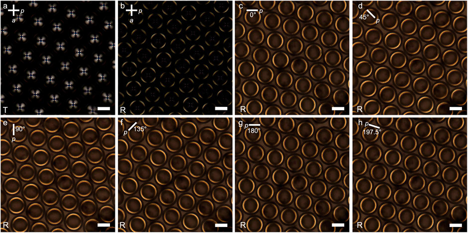
FIGURE 5. A set of thin-topped radially aligned E7 shells at 39°C observed between crossed polarizers in (A) transmission (T) and (B) in reflection (R), and in reflection without analyzer, with varying polarizer orientations as indicated by the line at the top left of each panel (C–H). Scale bar (thick white line) is 100 μm.
When removing the analyzer (c), we see that the two interruptions of the bright perimeter reflection along the polarizer disappear, and we instead have two bright arcs with their brightest and thickest points where the shell perimeter intersects the polarizer. As the polarizer is rotated (d–h and Supplementary Movie S2) we note that the texture follows continuously, the arcs rotating with the polarizer, the black spots separating them always being at the points where the normal to the polarizer intersects with the shell perimeter. To emphasize that the effect is fully continuous even without seeing the movie, we include one arbitrary polarizer orientation of 197.5° from the starting orientation in panel (h).
4 Discussion
Similar to the bright perimeters of short-pitch cholesteric shells discussed by Geng et al. (Geng et al. (2018), the bright spots and arcs observed with nematic E7 shells in this study are due to light guiding throughout the shell enabled by total internal reflection (TIR) of light that enters the shell near the top. Multiple TIR events prevent the light from escaping until it has made a U-turn, exiting the shell on the opposite side of the central axis along gravity, now directed upwards such that it can be detected by the observer. To understand why this happens, and why the light guiding is localized in different ways for different configurations of director field, we must first recall the condition for TIR and the corresponding light guiding (same effect as in optical fibers). In order to get TIR, the refractive index of the guiding medium must be greater than the surrounding, and this is indeed always the case for our E7 shells, which at the experimental temperature of 39° exhibit refractive indices n⊥ ≈ 1.525 and n‖ ≈ 1.71 (Li et al. (2005)). These are both significantly greater than the refractive index of the isotropic 1 wt% aqueous PVA solution used for internal and continuous phases, niso ≈ 1.36 (Panda et al. (2011)). However, a greater liquid crystal refractive index (nLC) than that of the PVA solution is not enough for TIR; the internal angle of incidence θLC must also be large enough that the refracted light would exit with an angle θiso of 90° or greater with respect to the interface normal, as given by Snell’s law:
Since θLC depends on the relative orientation of director and polarization, we may now start to understand the reason for the dependence on both director field and polarization of whether we see TIR-mediated light guiding within the shell. Inserting the values for n⊥ and n‖ of E7 at the experimental temperature we obtain the extreme values for the minimum angle θLC as:
In order to have a first TIR event within the shell, we see that the light must encounter the inner shell boundary at an angle no less than 63.1° and 52.7°, respectively, which requires the light ray that would undergo TIR to enter relatively close to the shell perimeter, as illustrated in Figure 6. As shown in panel (a), this condition is fulfilled when the light experiences the refractive index n⊥ inside the shell for an angle of entry into the shell of about 56.4°. This is fully reasonable as this propagation direction is included in the typical cone of illumination during microscopy. However, although a single TIR event would thus indeed be expected at the first liquid crystal–aqueous phase interface (on the shell inside), the reflected light beam encounters the outer shell interface at an angle of 59.3° which is lower than the minimum for TIR, hence the light leaks out of the shell at this point, in a near horizontal direction, as illustrated in Figure 6A. Even when we move closer to the perimeter, increasing the first TIR reflection angle to 75° (b) or 85° (c) the next reflection at the outer shell interface always occurs at too low angle to trigger the second TIR event required to keep the light in the shell for guiding, if the light experiences the ordinary refractive index, n⊥, of E7.
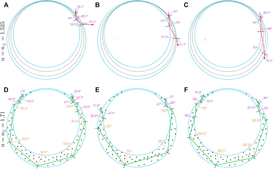
FIGURE 6. Exemplary potential TIR-mediated light guiding paths throughout an E7 shell at 39°C surrounded by 1 wt% aqueous PVA solutions, as in our experiments, for the cases that the light experiences n⊥ (A,B,C) and n‖ (D,E,F) of E7, respectively. While the latter leads to multi-TIR-event paths sending the light back to the observer, the ordinary refractive index is too low to avoid that the light leaves the shell into the continuous phase before it has completed a turn throughout the shell. The incoming light polarization is assumed to be perpendicular to the image plane and the director is drawn with dashed black lines in the top row, where the director is in the paper plane, and with black dots in the bottom row, symbolizing director perpendicular to the image plane. Refraction angles upon entry into or exit from the shell are indicated in purple, and internal reflection angles are indicated in orange and pink, for outer and inner side reflections, respectively.
In contrast, if the light experiences the higher refractive index n‖, the lower required incidence angle for TIR enables multiple light guiding paths around the shell, as shown in Figures 6D–F. Already for the case of vertical incidence within the shell barely fulfilling the requirement of
We can now qualitatively understand all experimental observations in Figures 4, 5 by considering which refractive index light experiences as it enters a shell, as a function of light polarization and director orientation at the point of entry. For the tangential-aligned shells, the director field is bent into the viewing direction along most points along the perimeter. Only at the top and bottom of Figure 2A, along the y-axis, does the shell show its full birefringence at the perimeter. This explains why it is only near these points that a TIR-mediated light guiding path similar to those shown in Figures 6D–F can be excited. At all other locations, light enters more or less along the director, thus along the optic axis, and it experiences the refractive index n⊥ regardless of its polarization, hence these regions never show the TIR-mediated light guiding. The same holds around the entire perimeter if the light is polarized along the y-axis, explaining why the reflection spot disappears whenever the illuminating light is polarized along the local y-axis of a shell. The reason that the isolated shell observed in transmission (Figure 4C) has dark arcs corresponding to the locations where the shell is bright in reflection (Figure 4G) is that the TIR-mediated light guiding prevents the illumination from below the sample to reach the observer at these spots during transmission POM. For other shells, all having neighbors in their direct vicinity, the relationship is less clear. A full analysis of the subtle varations of brightness in the transmission image is outside the scope of this paper.
Moving to the radially oriented shell, we can see in Figure 2C that the director near the perimeter, as it appears when the shell is observed from above, is oriented nearly into the image plane, pointing radially out from the central symmetry axis. This means that the full birefringence is available in any section of the perimeter, and if the light is polarized sufficiently close to the local optic axis orientation, it experiences a high enough refractive index to undergo the TIR-mediated light guiding through the shell. Only when the light is polarized nearly perpendicular to the local director does it experience only n⊥, yielding a too low refractive index to close the light guiding loop by TIR events. This explains the two antipodal dark spots rotating with the polarizer in Figure 5.
5 Conclusion and outlook
The birefringence of liquid crystals confined in shells can lead to polarization- and director field-sensitive total internal reflection (TIR) events of light that enters the shell during microscopic observation. This is recognized as bright spots or arcs on nematic shells that are tangentially or radially aligned, respectively, as well as by the possibility to block the spots in the former case or rotate the arcs in the latter case by rotating the polarization of the illuminating light. The effects depend quantitatively on the ordinary and extraordinary refractive indices of the liquid crystal, as well as of the refractive index of the surrounding isotropic liquids, hence tuning these parameters will offer additional means of activating or deactivating the light guiding. The shell geometry impacts the reflection angles, and thereby the possibility of TIR-mediated light guiding, strongly, hence varying the inner and outer shell radii and the asymmetry of the shell offers another means of tuning the reflection behavior.
Awareness of these phenomena can be useful in the characterization of liquid crystal shells, even for non-chiral liquid crystal phases that exhibit no inherent reflection phenomena, in particular for establishing the orientations of shells with tangential alignment. Since polymerization of reactive liquid crystals is often triggered by light irradiation, taking the possible light guiding paths into account may be vital for successful polymerization and it may offer an interesting handle for restricting polymerization to specific paths within each shell. Also after polymerization, the TIR-mediated internal reflection may be of interest in case of light-triggered liquid crystal elastomer shells, where the mode of actuation may thus be modulated by changing the polarization of the illuminating light. For applications of cholesteric liquid crystal shells, it is also important to be aware of the light guiding possibilities, since this may compete with the Bragg reflections that are typically desired in these scenarios. The indiscriminate TIR-mediated light guiding might broaden laser emission bands and render shells visible outside the intended polarization and wavelength spectrum.
Data availability statement
The original contributions presented in the study are included in the article/Supplementary Material, further inquiries can be directed to the corresponding author.
Author contributions
NP prepared all shells and made the original observation of the reflection spots and arcs. NP and JL did the optical microscopy experiments described in the manuscript together and JL wrote most of the paper, with input from NP.
Funding
This research was carried out without any external funding.
Acknowledgments
We thank Yong Geng for fruitful discussions.
Conflict of interest
The authors declare that the research was conducted in the absence of any commercial or financial relationships that could be construed as a potential conflict of interest.
Publisher’s note
All claims expressed in this article are solely those of the authors and do not necessarily represent those of their affiliated organizations, or those of the publisher, the editors and the reviewers. Any product that may be evaluated in this article, or claim that may be made by its manufacturer, is not guaranteed or endorsed by the publisher.
Supplementary material
The Supplementary Material for this article can be found online at: https://www.frontiersin.org/articles/10.3389/frsfm.2022.991375/full#supplementary-material
References
Arenas, M. P., Demirci, H., and Lenzini, G. (2022). An analysis of cholesteric spherical reflector identifiers for object authenticity verification. Mach. Learn. Knowl. Extr. 4, 222–239. doi:10.3390/make4010010
Bates, M., Skacej, G., and Zannoni, C. (2010). Defects and ordering in nematic coatings on uniaxial and biaxial colloids. Soft Matter 6, 655–663. doi:10.1039/b917180k
Chen, H., Wang, X., Bisoyi, H., Chen, L., and Li, Q. (2021). Liquid crystals in curved confined geometries: Microfluidics bring new capabilities for photonic applications and beyond. Langmuir 37, 3789–3807. doi:10.1021/acs.langmuir.1c00256
Durey, G., Ishii, Y., and Lopez-Leon, T. (2020). Temperature-driven anchoring transitions at liquid crystal/water interfaces. Langmuir 36, 9368–9376. doi:10.1021/acs.langmuir.0c00985
Fernandez-Nieves, A., Vitelli, V., Utada, A., Link, D. R., Marquez, M., Nelson, D. R., et al. (2007). Novel defect structures in nematic liquid crystal shells. Phys. Rev. Lett. 99, 157801. doi:10.1103/physrevlett.99.157801
Fleischmann, E.-K., Liang, H.-L., Kapernaum, N., Giesselmann, F., Lagerwall, J. P. F., and Zentel, R. (2012). One-piece micropumps from liquid crystalline core-shell particles. Nat. Commun. 3, 1178. doi:10.1038/ncomms2193
Geng, Y., Jang, J.-H., Noh, K.-G., Noh, J., Lagerwall, J. P., and Park, S.-Y. (2018). Through the spherical looking-glass: Asymmetry enables multicolored internal reflection in cholesteric liquid crystal shells. Adv. Opt. Mat. 6, 1700923. doi:10.1002/adom.201700923
Geng, Y., Kizhakidathazhath, R., and Lagerwall, J. P. F. (2021). Encoding hidden information onto surfaces using polymerized cholesteric spherical reflectors. Adv. Funct. Mat. 31, 2100399. doi:10.1002/adfm.202100399
Geng, Y., Noh, J., Drevensek-Olenik, I., Rupp, R., Lenzini, G., and Lagerwall, J. P. F. (2016a). High-fidelity spherical cholesteric liquid crystal Bragg reflectors generating unclonable patterns for secure authentication. Sci. Rep. 6, 26840. doi:10.1038/srep26840
Geng, Y., Noh, J., and Lagerwall, J. P. F. (2016b). “Transmission polarized optical microscopy of short-pitch cholesteric liquid crystal shells,” in Proc. SPIE 9769, Emerging Liquid Crystal Technologies XI, 97690U.
Gollapelli, B., and Vallamkondu, J. (2019). Electric field-driven structural changes in cholesteric shells for optical applications. Curr. Appl. Phys. 19, 1399–1403. doi:10.1016/j.cap.2019.09.006
Ishii, Y., Zhou, Y., He, K., Takanishi, Y., Yamamoto, J., de Pablo, J., et al. (2020). Structural transformations in tetravalent nematic shells induced by a magnetic field. Soft Matter 16, 8169–8178. doi:10.1039/d0sm00340a
Iwai, Y., Iijima, R., Yamamoto, K., Akita, T., Uchida, Y., and Nishiyama, N. (2020). Shrinkage of cholesteric liquid crystalline microcapsule as omnidirectional cavity to suppress optical loss. Adv. Opt. Mat. 8, 1901363. doi:10.1002/adom.201901363
Jampani, V. S. R., Mulder, D. J., De Sousa, K. R., Gélébart, A.-H., Lagerwall, J. P. F., and Schenning, A. P. H. J. (2018). Micrometer-scale porous buckling shell actuators based on liquid crystal networks. Adv. Funct. Mat. 28, 1801209. doi:10.1002/adfm.201801209
Jampani, V. S. R., Volpe, R. H., Reguengo de Sousa, K., Ferreira Machado, J., Yakacki, C. M., and Lagerwall, J. P. F. (2019). Liquid crystal elastomer shell actuators with negative order parameter. Ph.D. thesis (Washington, D.C., USA: American Association for the Advancement of Science).
Kang, J., Kim, S., Fernandez-Nieves, A., and Reichmanis, E. (2017). Amplified photon upconversion by photonic shell of cholesteric liquid crystals. J. Am. Chem. Soc. 139, 5708–5711. doi:10.1021/jacs.7b01981
Kim, J.-G., and Park, S.-Y. (2017). Photonic spring-like shell templated from cholesteric liquid crystal prepared by microfluidics. Adv. Opt. Mat. 5, 1700243. doi:10.1002/adom.201700243
Koning, V., Lopez-Leon, T., Darmon, A., Fernandez-Nieves, A., and Vitelli, V. (2016). Spherical nematic shells with a threefold valence. Phys. Rev. E 94, 012703. doi:10.1103/physreve.94.012703
Koning, V., Lopez-Leon, T., Fernandez-Nieves, A., and Vitelli, V. (2013). Bivalent defect configurations in inhomogeneous nematic shells. Soft Matter 9, 4993–5003. doi:10.1039/c3sm27671f
Kralj, S., Rosso, R., and Virga, E. G. (2011). Curvature control of valence on nematic shells. Soft Matter 7, 670–683. doi:10.1039/c0sm00378f
Lee, S., Seo, H., Kim, Y., and Kim, S. (2017). Liquid crystals: Structural color palettes of core-shell photonic ink capsules containing cholesteric liquid crystals (adv. Mater. 23/2017). Adv. Mat. 29, 1606894. doi:10.1002/adma.201770163
Li, J., Wu, S.-T., Brugioni, S., Meucci, R., and Faetti, S. (2005). Infrared refractive indices of liquid crystals. J. Appl. Phys. 97, 073501. doi:10.1063/1.1877815
Liang, H.-L., Enz, E., Scalia, G., and Lagerwall, J. (2011a). Liquid crystals in novel geometries prepared by microfluidics and electrospinning. Mol. Cryst. Liq. Cryst. 549, 69–77. doi:10.1080/15421406.2011.581140
Liang, H.-L., Schymura, S., Rudquist, P., and Lagerwall, J. (2011b). Nematic-smectic transition under confinement in liquid crystalline colloidal shells. Phys. Rev. Lett. 106, 247801. doi:10.1103/physrevlett.106.247801
Liang, H., Noh, J., Zentel, R., Rudquist, P., and Lagerwall, J. (2013). Tuning the defect configurations in nematic and smectic liquid crystalline shells. Phil. Trans. R. Soc. A 371, 20120258. doi:10.1098/rsta.2012.0258
Lopez-Leon, T., and Fernandez-Nieves, A. (2011). Drops and shells of liquid crystal. Colloid Polym. Sci. 289, 345–359. doi:10.1007/s00396-010-2367-7
Lopez-Leon, T., Fernandez-Nieves, A., Nobili, M., and Blanc, C. (2011a). Nematic-smectic transition in spherical shells. Phys. Rev. Lett. 106, 247802. doi:10.1103/physrevlett.106.247802
Lopez-Leon, T., and Fernandez-Nieves, A. (2009). Topological transformations in bipolar shells of nematic liquid crystals. Phys. Rev. E 79, 021707. doi:10.1103/physreve.79.021707
Lopez-Leon, T., Koning, V., Devaiah, K. B. S., Vitelli, V., and Fernandez-Nieves, A. (2011b). Frustrated nematic order in spherical geometries. Nat. Phys. 7, 391–394. doi:10.1038/nphys1920
Mirantsev, L V., Sonnet, A. M., and Virga, E. G. (2012). Geodesic defect anchoring on nematic shells. Phys. Rev. E 86, 020703. doi:10.1103/physreve.86.020703
Myung, D., and Park, S. (2019). Optical properties and applications of photonic shells. ACS Appl. Mat. Interfaces 11, 20350–20359. doi:10.1021/acsami.9b04105
Napoli, G., and Vergori, L. (2021). Cooling a spherical nematic shell. Phys. Rev. E 104, L022701. doi:10.1103/physreve.104.l022701
Napoli, G., and Vergori, L. (2012). Extrinsic curvature effects on nematic shells. Phys. Rev. Lett. 108, 207803. doi:10.1103/physrevlett.108.207803
Noh, J., Henx, B., and Lagerwall, J. P. (2016a). Taming liquid crystal self-assembly: The multifaceted response of nematic and smectic shells to polymerization. Adv. Mat. 28, 10170–10174. doi:10.1002/adma.201603158
Noh, J., Jampani, V. S. R., Haba, O., Yonetake, K., Takezoe, H., and Lagerwall, J. P. (2018). Sub-second dynamic phototuning of alignment in azodendrimer-doped nematic liquid crystal shells. J. Mol. Liq. 267, 197–204. doi:10.1016/j.molliq.2018.02.004
Noh, J., Reguengo De Sousa, K., and Lagerwall, J. P. F. (2016b). Influence of interface stabilisers and surrounding aqueous phases on nematic liquid crystal shells. Soft Matter 12, 367–372. doi:10.1039/c5sm01944c
Noh, J., Wang, Y., Liang, H.-L., Jampani, V. S. R., Majumdar, A., and Lagerwall, J. P. F. (2020). Dynamic tuning of the director field in liquid crystal shells using block copolymers. Phys. Rev. Res. 2, 033160. doi:10.1103/physrevresearch.2.033160
Panda, S., Mohanty, G. C., Roy, G., and Sahoo, K. (2011). Determination of surface tension, optical rotativity and refractive index of polymer polyvinyl alcohol pva, in various solvents at different concentrations. Lat. Am. J. Phys. Educ. 5, 734.
Park, S., Lee, S., and Kim, S. (2020). Photonic multishells: Photonic multishells composed of cholesteric liquid crystals designed by controlled phase separation in emulsion drops (adv. Mater. 30/2020). Adv. Mat. 32, 2070227. doi:10.1002/adma.202070227
Schwartz, M., Geng, Y., Agha, H., Kizhakidathazhath, R., Liu, D., Lenzini, G., et al. (2021). Linking physical objects to their digital twins via fiducial markers designed for invisibility to humans. Multifunct. Mat. 4, 022002. doi:10.1088/2399-7532/ac0060
Schwartz, M., Lenzini, G., Geng, Y., Rønne, P., Ryan, P., and Lagerwall, J. (2018). Cholesteric liquid crystal shells as enabling material for information-rich design and architecture. Adv. Mat. 30, 1707382. doi:10.1002/adma.201707382
Sharma, A., Gupta, D., Scalia, G., and Lagerwall, J. P. F. (2022). Lipid islands on liquid crystal shells. Phys. Rev. Res. 4, 013130. doi:10.1103/physrevresearch.4.013130
Sharma, A., Jampani, V., and Lagerwall, J. (2019). Realignment of liquid crystal shells driven by temperature-dependent surfactant solubility. Langmuir 35, 11132–11140. doi:10.1021/acs.langmuir.9b00989
Sharma, A., and Lagerwall, J. P. F. (2018). Influence of head group and chain length of surfactants used for stabilising liquid crystal shells. Liq. Cryst. 45, 2319–2328. doi:10.1080/02678292.2018.1509391
Sharma, A., Stoffel, A. M., and Lagerwall, J. P. F. (2021). Liquid crystal elastomer shells with topological defect-defined actuation: Complex shape morphing, opening/closing, and unidirectional rotation. J. Appl. Phys. 129, 174701. doi:10.1063/5.0044920
Skacej, G., and Zannoni, C. (2008). Controlling surface defect valence in colloids. Phys. Rev. Lett. 100, 197802. doi:10.1103/physrevlett.100.197802
Uchida, Y., Takanishi, Y., and Yamamoto, J. (2013). Controlled fabrication and photonic structure of cholesteric liquid crystalline shells. Adv. Mat. 25, 3234–3237. doi:10.1002/adma.201300776
Urbanski, M., Reyes, C. G., Noh, J., Sharma, A., Geng, Y., Jampani, V. S. R., et al. (2017). Liquid crystals in micron-scale droplets, shells and fibers. J. Phys. Condens. Matter 29, 133003. doi:10.1088/1361-648x/aa5706
Utada, A., Lorenceau, E., Link, D. R., Kaplan, P. D., Stone, H. A., and Weitz, D. A. (2005). Monodisperse double emulsions generated from a microcapillary device. Science 308, 537–541. doi:10.1126/science.1109164
Keywords: liquid crystal shells, total internal reflection, light guiding, birefringence, polarized light, polarizing microscopy
Citation: Popov N and Lagerwall JPF (2022) Birefringence-modulated total internal reflection in liquid crystal shells. Front. Soft. Matter 2:991375. doi: 10.3389/frsfm.2022.991375
Received: 11 July 2022; Accepted: 03 August 2022;
Published: 30 August 2022.
Edited by:
Hiroshi Yokoyama, Kent State University, United StatesReviewed by:
Hiroyuki Yoshida, Osaka University, JapanYoungki Kim, Pohang University of Science and Technology, South Korea
Qi-Huo Wei, Southern University of Science and Technology, China
Copyright © 2022 Popov and Lagerwall. This is an open-access article distributed under the terms of the Creative Commons Attribution License (CC BY). The use, distribution or reproduction in other forums is permitted, provided the original author(s) and the copyright owner(s) are credited and that the original publication in this journal is cited, in accordance with accepted academic practice. No use, distribution or reproduction is permitted which does not comply with these terms.
*Correspondence: Jan P. F. Lagerwall, SmFuLkxhZ2Vyd2FsbEBsY3NvZnRtYXR0ZXIuY29t
†ORCID ID: Nikolay Popov, orcid.org/0000-0002-4540-6616; Jan P. F. Lagerwall, orcid.org/0000-0001-9753-1147