 Chen Qian
 Li Hui1
 Wen Jiming
 Tan Sichao
- 1Heilongjiang Provincial Key Laboratory of Nuclear Power System and Equipment, Harbin Engineering University, Harbin, China
- 2Science and Technology on Thermal Energy and Power Laboratory, Wuhan Second Ship Design and Research Institute, Wuhan, China
Introduction: The direct-contact condensation (DCC) of steam under water injection is the basic thermodynamic process of the bubble deaerator. In order to understand the complex coupling behavior of strong turbulence and fast phase-change heat transfer involved in the process.
Methods: This study uses a visualized method and convective heat transfer model.
Results: Since the contact area is affected by steam injection flow and sub-cooled degree is affected simultaneously, the trend of the condensation heat-transfer coefficient depends on the degree of their respective effects under each condition, and the maximum variation of the coefficient exceeds 104 W/m2.°C. Moreover, they still effect the period of steam plume, and the maximum variation of the period was beyond 80 ms.
Discussion: Calculated the average condensation heat transfer coefficient and then produces the variation law of heat transfer coefficient under various conditions in one steam plume evolution period.
1 Introduction
The bubble deaerator, as one of the deoxygenation equipment, has been wildly used in nuclear power plants. In order to extract the non-condensable gases that have dissolved inside the water, letting the superheated steam have direct contact with sub-cooled water is the main process of this equipment, and the water will be heated to the saturate temperature by the thermal energy generated from steam bubble collapse. The advantages of this process are zero-heat resistance and efficient heat transfer. However, the disadvantages still obviously are as follows: the high temperature difference between the superheated steam and sub-cooled water will cause the steam to condense rapidly near the nozzle and collapse after necking, and the jet noise will be radiated out due to the high-speed shear layer and strong turbulent region generated by steam bubble breakage. Therefore, the study of the condensation heat transfer characteristics on steam underwater injection plays an important role in understanding the heat transfer and noise mechanism of steam injection, and provides theoretical support for intensifying heat transfer and noise suppression.
The gas–liquid interfacial characteristic of the steam underwater injection is a fundamental basis for the study of DCC between steam and sub-cooled water. In this study, it determines the heat transfer area which affects the heat transfer coefficient. Due to the complication of the phenomenon, many scholars, based on the experimental investigations they conducted, presented the steam condensation diagram. In the 1980s Chan and Lee (1982); Fukuda and Saitoh (1982); Izuo et al. (1983); and Izuo et al. (1980) carried out pioneering research in this field, and various experimental condensation regime maps were drawn. Since the 2000s, Petrovic de With et al. (2007) presented a new three-dimensional condensation regime diagram because the two-dimensional diagram failed to predict regimes accurately if a different injector size was considered. de With (2009) presented a new two-dimensional steam plume penetration length diagram in order to predict the steam plume heat-transfer interface area in different conditions instead of repetitive experimental study, and he validated the diagram against experiments. Through the investigated flow regime maps, the experimental condition of this study could be settled in a proper range.
Due to the intense mass and energy exchange between steam and sub-cooled water, it is difficult to study its heat and mass transfer characteristics. Therefore, plenty of scholars have carried out experimental studies in DCC. In the 1970s, Cumo et al. (1977) studied the condensation heat transfer of conical steam jets by experimental investigation. Furthermore, the experimental analysis of conical, ellipsoidal, and divergent steam jets by Chun et al. (1996) showed that when the mass flux of steam increased or the temperature of water decreased, the average heat transfer coefficient increased. Xu et al. (2022b) carried out both experimental and numerical studies of DCC in sub-cooled water pipe flow, based on the experimental data and numerical solutions, they found that mass transfer reaches the maximum at the phase interface with a steam volume fraction of 0.60. Yang et al. (2019) conducted an experimental investigation to study the thermal hydraulic characteristics of DCC in an unstable condensation regime, and according to the experimental results at various boundary conditions, they presented a unified correlation of the heat transfer coefficient which identified the bubbling frequency in the unstable condensation regime. Kwidzinski (2021) analyzed the heat and mass transfers in the mixing chamber of steam–water injector; he found that the two-phase flow parameters of the mixing chamber outlet depending predominantly on the inlet water–vapor temperature difference.
For conducting further experiments and reducing the repetitive experiments, many scholars also carried out numerical studies in DCC. Gulawani et al. (2006) used the two-resistance thermal phase-change model to simulate the DCC of a steam jet; this model considered both the heat transfers from the ambient water to the steam–water interface and from the steam region to the steam–water interface. Li et al. (2015) used the Volume of Fluid (VOF) multiphase model and Large Eddy Simulation (LES) turbulent model to investigate DCC; comparing the simulation solution and the experimental data, they were in good agreement in steam plume evolution, and the steam plume can be divided into four stages. Pesetti et al. (2020) investigated the DCC phenomenon in a vacuum vessel pressure-suppression system of nuclear fusion plants. Through the adoption and assessment of suitable numerical codes, it was able to precisely simulate low-pressure steam injection and sub-cooled water’s initial thermodynamic parameters. Lu et al. (2021) investigated the DCC characteristic through a double-hole nozzle under different conditions; the experimental data indicate that the heat transfer coefficient of the double-hole steam jet is closely related to the sub-cooled water temperature and steam mass flux. Li et al. (2022) used Lee mass transfer model to investigate the interfacial characteristics, with reference to experiment data they obtained; it was demonstrated that the mass transfer rate caused velocity fluctuations at the steam–water interface, and these velocity fluctuations promoted bubble deformation. Xu et al. (2022a) conducted CFD research using the Eulerian two-fluid model on the DCC phenomenon; based on the simulation solution, they discovered the correlation between steam plume’s Ma number and the total pressure at the nozzle outlet.
After entering the sub-cooled water through the discharge nozzle, the steam jet will violently transfer heat and mass to the surrounding sub-cooled water, accompanied by the kinetic energy carried by itself. Thus, the phenomenon of fluid and pressure oscillations will be introduced, that also produce noise. In the 1970s, Kadlec and Müller (1976), through full-scale containment tests conducted for Marviken NPP in Sweden, indicated that steam jet condensation had an important influence on the pressure oscillation. Li et al. (2019) and Li et al. (2020) carried out experimental studies on pressure oscillation in pure steam injection and steam–air mixture injection. The experimental result showed that in pure steam injection, the pressure oscillation intensity in sub-cooled water increases first, then decreases rapidly, and then increases slowly; in a mix injection, the presence of air can reduce the pressure oscillation intensity when bubble resonance does not occur,. Datta et al. (2021) carried out an experimental investigation of the DCC phenomenon in a horizontal pipe; considering the experimental data, they found that pressure peaks are attributed to the rapid collapse of vapor bubbles when the corresponding locations become filled with sub-cooled water. Miwa et al. (2021) experimentally investigated DCC in a steam–water condensing injector; they used supersonic steam and a sub-cooled water jet, and based on the experimental data, they established a one-dimensional model to predict the axial pressure distribution. Li et al. (2021b), in order to relieve the drawback of this process, carried out an experimental study on it, and finally designed three types of sprayers to reduce the pressure oscillation in high-steam mass flow rate. Liu et al. (2022) carried out an experimental study of condensation oscillation induced by steam injected through a vertical blow down pipe and found that the vessel pressure has a significant effect on the condensation oscillations.
For avoiding greater damage generated by intense pressure oscillation of the steam jet on the experimental facility, scholars conducted numerical investigations on this. Pttikangas et al. (2010) noted that the difficulty of DCC lies in the calculation of the interface area and heat transfer coefficient. The VOF model was suitable for simulating large bubbles of non-condensable gas in the early discharge stage of a pressure suppression pool. Zhou et al. (2021) took numerical investigations of DCC in a vertical pipe with the presence of non-condensable gas and revealed that the steam plume static pressure peak is affected by the squeezing effect of water flow. Li et al. (2021a) also carried out a CFD study of DCC in this aspect and found six large chugging stages in steam–water flow which may cause oscillations.
Other scholars also tried to investigate the mechanism of DCC or reduce the pressure oscillation using various methods. Chen et al. (2019) carried out a visualized study on DCC in convergent nozzle over a wide range of operating conditions, discussing in detail the steam plume shape, penetration length, and average heat-transfer coefficient, by means of fitting measured data, they presented empirical correlations for dimensionless penetration length and average heat transfer coefficient as a function of dimensionless steam mass flux and condensation driving potential. Zhu et al. (2021) experimentally studied DCC in core make-up tank (CMT) in AP-series nuclear power plants, in order to reveal that the CMT behavior was affected by different factors including pressure, non-condensable gas, and thermal resistance. Wang et al. (2021a) experimentally studied the temperature and pressure oscillation induced by DCC in a porous injector, and through the experimental data, they found that the porous inner-structure suppressed the pressure oscillation by increasing the viscous resistance and inertia resistance of the steam–water flow.
Through the aforementioned literature review and the other review articles (Wang et al., 2021b), it was found that the current research on the phase-change heat transfer of steam condensation is still mainly focused on the flow field of medium and high sub-cooled degrees, and there have been few studies under the low-sub-cooled-degree condition, because of the weak cooling capacity of ambient water. Currently, the steam jet plume form becomes instability, and the identification of the gas–liquid interface becomes difficult. Therefore, the aim of this study is to enhance our understanding of the heat transfer characteristics of steam–water direct-contact condensation under low sub-cooled degree and analyze the variation law of heat transfer coefficient with different injection and ambient water parameters, and finally, to obtain the thermodynamic behavior of the steam injection process under a low-sub-cooled flow field.
2 Experimental facility
The experimental facility is shown in Figure 1. It mainly consists of a steam generator, main and auxiliary steam branches, one low-sub-cooled visualize water tank, with a size of 1,500 mm × 600 mm × 1,000 mm, a high-speed camera, several pressure, temperature gauges, and two vortex flow meters mounted on the pipeline; the range of steam injection mass flux is 10–240 kg/(m2∙s). The superheated steam generated by the steam generator enters the steam pipeline after passing through the surge tank. The main steam branch is connected to the water tank, and steam enters the water tank through the steam nozzle with a diameter of 6 mm installed at the end of the pipeline. The high-speed camera will record the condensation-collapse behavior under steam injection conditions. The auxiliary steam pipeline controls the flow rate of steam injected into the water tank via the valve installed on the pipeline. The diverted steam enters the condensing tank and then flows back to the steam generator after condensing.
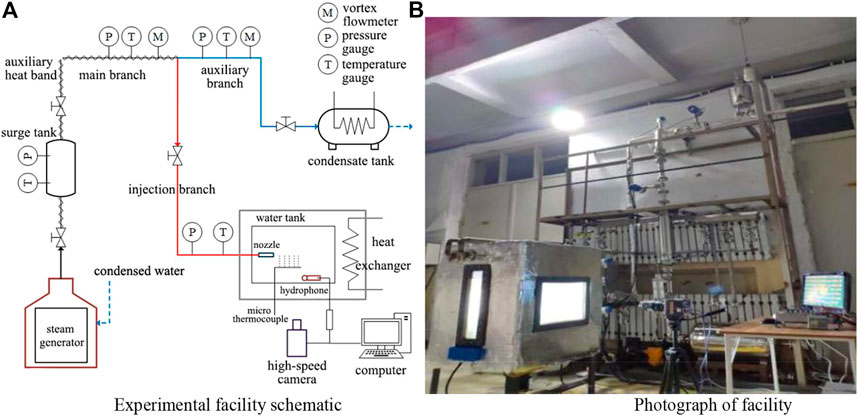
Figure 1. Schematic of the experimental system. (A) Experimental facility schematic. (B) Photograph of the facility.
The actual steam volume flow rate injected into the water tank can be calculated by subtracting the steam flow rate of the main and auxiliary steam branches. This method effectively restricts the issue of the low flow rate affected by the opening of the valve on a single pipe. An auxiliary electric heating band is wrapped on the main steam branch. In order to compensate the heat dissipation to the environment when steam passes through the pipeline, this device will start before the beginning of the experiment to ensure that the steam passing through the flow meter and then entering the water tank is in a saturate state, the steam pressure at nozzle inlet is at a range of 0.1–0.2 MPa (absolute pressure). The water tank was also equipped with a backlight panel, a cooling heat exchanger, some thermocouple for measuring the water temperature near the nozzle, and a hydrophone for measuring the noise of steam bubble collapse. An air extractor was connected with the air extraction hole set on the water tank, operating pressure (absolute pressure) of the water tank is 0.05 MPa, lower than the atmospheric pressure to reduce the saturate temperature from 100°C to 81°C, so that the water can reach the required sub-cooled degree without raising the temperature to a very high level. That improves the safety of thermal–hydraulic experiments. The main parameters of the measuring instruments are shown in Table 1.
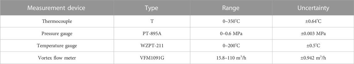
Table 1. Main parameters of the experimental measuring instrument.
During the experiment, the steam status parameters inside the pipeline are adjusted to satisfy the required working conditions. A high-speed camera capturing the steam plume image simultaneously is arranged near the visual observation window on the other side of the water tank. The steam plume images are used to assist the analysis of the condensation heat transfer mechanism and obtain the thermodynamic behavior of the steam injection process in the low-sub-cooled flow field. Each experimental condition of steam injection can be seen in Table 2.
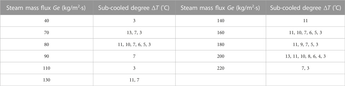
Table 2. Experimental conditions.
3 Data acquisition
This section will introduce the steps to calculate the heat transfer coefficient, including the convective heat transfer model, the method to obtain the temperature near nozzle, and the area of gas–liquid interface.
3.1 Convective heat transfer model and temperature measurement position
In order to investigate the condensation heat transfer characteristics of steam underwater injection, many scholars have carried out experimental studies. Among them, the convective heat transfer model is developed based on the conservation of energy transfer through the interface. The primary hypothesis of this model is that the energy conservation in a gas–liquid interface, that is, the energy transfer from steam to the ambient water through the phase interface is equal to the energy absorbed by the ambient water, and establishes the thermal balance equation through the gas–liquid interface as follows:
where hi is the heat transfer coefficient. From the formula mentioned above, we have
Once the volume flow rate has been obtained, recording the steam status parameter data by the temperature and pressure gauge mounted on the pipeline and dividing the specific volume, the mass flow rate m can be obtained. Dividing the nozzle cross section area can finally get the steam injection mass flux Ge. Tf is the ambient water temperature, it is taken as the average value of the two thermocouples on both sides of the steam plume and the four thermocouples arranged at the four corners of the water tank (Tf1, Tf2, Tf3, Tf4, Tf5, and Tf6). Ts is the steam plume temperature, it is taken as the average value of the temperature-measuring position (Ts1, Ts2, Ts3, and Ts4) arranged inside the steam plume. The measurement of the temperature inside the steam plume requires the thermocouples to enter the steam plume in an appropriate depth. If they are too deep, the development of the steam plume will affect them; and if they are too shallow, even being located in sub-cooled water will result in an inaccurate temperature measurement. Therefore, the arrangement of thermocouples near the nozzle is roughly as follows: four thermocouples at the nozzle outlet are installed at a movable bracket; the measuring point position can be changed according to the variation of the steam plume’s penetration length. The temperature-measuring point is arranged as shown in Figure 2.
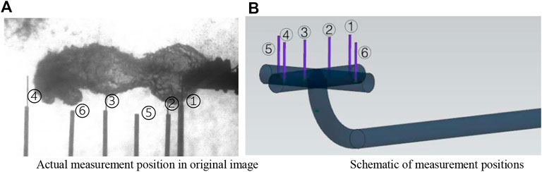
Figure 2. Schematic of measurement positions around and inside the steam bubble. (A) Actual measurement position in the original image. (B) Schematic of measurement positions.
The enthalpy value hf of the ambient water is calculated by using the ambient water temperature, Tf, and the indication of pressure gauge mounted on the water tank.
3.2 Image process
Identifying the boundary of gas–liquid interface is one of the necessary steps to obtain the condensation heat transfer coefficient, the other one is to obtain the gas–liquid heat exchange area. However, the shape of steam underwater injection becomes irregular and periodic under the condition of low sub-cooled degree and low mass flow rate. Therefore, for the typical steam plume shape, this study uses a high-speed camera to capture the steam plume image, then analyzes the steam plume evolution period in different conditions, processes the steam plume image in each period, and obtains the variation heat-transfer characteristics. In order to distinguish each period, the definition of one steam plume evolution period is: the time the last bubble necking completely leaves the nozzle is the starting of the period, when the steam plume completely leaves the nozzle and collapses at the end of this period. The heat transfer area of the gas–liquid interface is obtained by processing the steam plume image of one period, and then calculating the heat transfer coefficient of the underwater jet.
The steam plume image captured by a high-speed camera will adjust to remove the noise around the steam plume, due to the environmental disturbances and imperfections of the optical system, then binaries through threshold segmentation. The key to this method is to find the appropriate grayscale threshold, usually according to the grayscale histogram of this image, and then select Otsu’s method. This algorithm divides the grayscale value of the image into two parts through the threshold, giving max variance between the two parts. Image segmentation will be performed after the global threshold is obtained. The comparison between the binarized image obtained by this method and the original image is shown in Figure 3. The image represents the condition of the sub-cooled degree ΔT = 10°C, and the mass flux Ge = 180 kg/m2·s.
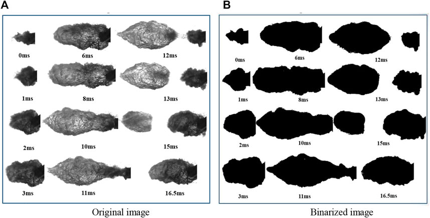
Figure 3. Comparison of the original image and binarized image. (A) Original image. (B) Binarized image.
After obtained the binarized image of the steam plume, it will be processed to identify the gas–liquid interface area. Assuming that the gas–liquid interface is axisymmetric and continuous, it can be solved by the following equation:
Among them, in Eq. 3, the upper limit of integration l is the penetration length of the vapor plume, where dx is the length of the differential element, and r is the axial radius of the jet. The captured vapor plume images will be processed to obtain the boundary pixels at the gas–liquid interface and then fit the upper and lower interface boundary curves. The distance between the midpoint of the upper and lower boundary curves and the injection axis is the jet axial radius r. The penetration length l is determined by the maximum continuous point’s abscissa of the gas–liquid interface. The length of the differential element is set as one pixel, and the actual distance of the pixel is determined by the outer nozzle’s diameter of 12 mm; it is occupying 45 pixels on each image, so the actual distance of one pixel is 0.267 mm, and the gas–liquid heat exchange area A can be calculated via the aforementioned parameters.
In the process of calculating the interfacial area, the deviation of it is mainly caused by device measurement, for this study, the high-speed camera is the main source of the uncertainty. There are two parts as the sources of uncertainty: the error caused by calibration of physical distance, and the image distortion caused by camera assembly. The error calculation results are shown in Table 3.
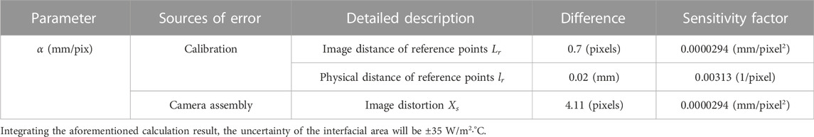
Table 3. Error calculation result.
4 Analysis of influencing factors of condensation heat transfer
There are lots of factors that can affect the condensation heat-transfer characteristics. The sub-cooled degree and steam flow rate are the main influencing factors among them. The sub-cooled degree represents the relative degree of steam condensation potential, the greater the steam condensation potential, the stronger cooling capacity of ambient water. The steam mass flow rate represents the jet velocity potential and it indicates the degree of turbulence between the steam generated by the velocity shear stress and the surrounding water. Therefore, this study mainly analyzes the heat-transfer characteristics of steam-injection condensation from these two aspects. Since the jet is in an unstable state, the condensation heat-transfer characteristics under each condition cannot be represented only by the average heat-transfer coefficient. Therefore, it is necessary to analyze not only the average heat-transfer characteristics in different conditions, but also to analyze the average heat-transfer characteristics during the steam plume evolution period.
4.1 Effects of different steam flow rates
When the ambient water has reached a high sub-cooled degree, the steam plume evolution will have a short period, and the steam plume will experience three processes of periodic initial growth, necking detachment, and condensation collapse as the jet progresses. In the initial growth state, the volume of the steam plume is small, and so as the heat exchange area between it and the surrounding water, because of the effect of the jet velocity potential, and the heat exchange capacity of the steam bubble is stronger than other stages. With the subsequent push of steam, the shape of the steam plume changes, the steam bubble grows greater, the interface area increases, and the heat-transfer capacity weakens under the same inputted energy. As the bubble necking and detach away, the reduced bubble volume and interfacial area lead to an increase in the cooling capacity toward the end of the jet. But, its heat transfer coefficient compared with that of initial the growth stage is still relatively low. When the steam flow rate is high, the initial stage’s condensation heat transfer coefficient has a higher value than that of other lower steam flow rate conditions; as for the effect of jet’s velocity potential, it has a more intense condensation behavior. When the steam flow rate becomes low, the change of the heat-transfer coefficient at the end stage of the jet flow happens smoothly, as affected by the velocity potential, the growth and collapse conditions of the steam plume are basically in a state of equilibrium. Figure 4 shows the variation curve of the condensation heat-transfer characteristics of ambient water in a high sub-cooled degree (ΔT = 11°C).

Figure 4. Condensation heat-transfer characteristic curve at 11°C sub-cooled temperature. (A) Heat-transfer characteristics in one period. (B) The variation of the average heat-transfer coefficient.
It can be seen from the figure that with the increases of the steam flow rate, the condensation heat-transfer coefficient shows a generally upward trend, but when the steam flow rate is at a medium flow rate, the heat transfer coefficient has a violent oscillation, which does not show any obvious regularity. The reason is that, on one hand, the increase of steam flow produces a more violent turbulence, which is beneficial to the condensation heat exchange process. On the other hand, the increase of steam flow leads to an increase in input energy, which is harmful to heat exchange. The relative degree of the two determines the condensation steam plume, as the plume shape changes, which in turn affects the condensation heat transfer process. The lower the mass flow rates, the higher the cooling capacity of ambient water; so, the input energy is relatively low, and the turbulence enhancement effect of ambient water is greater than that of the input energy. When the steam flow rate is high, the turbulent effect increases, and causes condensation which is greater than the increment of inputted energy, thus leading to the coefficients generally showing an upward trend, with oscillations at moderate mass flow rates.
When the sub-cooled degree is reduced to 7°C, as shown in Figure 5, the change of the condensation heat transfer coefficient in one period is basically as same as that of 11°C. With the development of the jet, the coefficient first decreases and then increases, but the maximum of coefficient reduces from 45,125 to 31,831, and the duration of the jet heat-transfer period also increases, the maximum period increases from 24 ms to 71 ms.
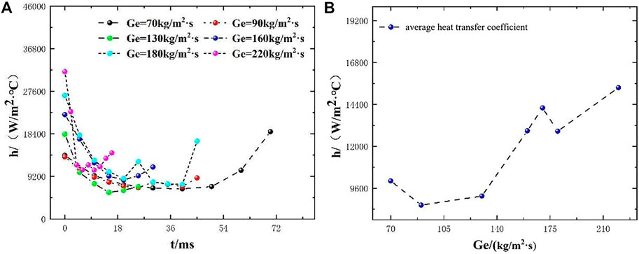
Figure 5. Condensation heat-transfer characteristic curve at 7°C sub-cooled temperature. (A) Heat transfer characteristics in one period. (B) The variation of the average heat-transfer coefficient.
When the sub-cooled degree of the ambient water continues decreasing to near saturation temperature, as shown in Figure 6, the steam inject condition at the sub-cooled degree reduces to 3°C. The oscillation of the heat transfer coefficient in the low-steam flow rate range becomes smoother than that of the high sub-cooled degree. The condensation potential of the jet is roughly the same as the cooling capacity of the ambient water, resulting in a small variation in the shape of the steam plume. When the steam flow rate is high, the condensation heat-transfer coefficient of the steam jet varies greatly and the duration of the heat exchange period decreases. The reason is that the steam jet velocity potential is in a predominant condition compared with the cooling capacity of ambient water. With the increase in jet velocity, the turbulent effect between steam and ambient water increases, and so the duration of the heat exchange period decreases.
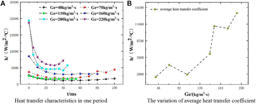
Figure 6. Condensation heat-transfer characteristic curve at 3°C sub-cooled temperature. (A) Heat transfer characteristics in one period. (B) The variation of average heat transfer coefficient.
With the increase of steam flow rate, the condensation heat transfer coefficient gradually increases; at this time, since the ambient water is close to the saturation temperature, the cooling capacity is greatly reduced, and the enhanced condensation effect caused by turbulence in a predominant role. Therefore, with the increase of steam flow, the average condensation heat transfer coefficient increases.
4.2 Effects of different sub-cooled degrees
This section will analyze the variation of condensation heat-transfer characteristics in different sub-cooled conditions and obtain the condensation heat-transfer characteristics in a low sub-cooled degree.
When the steam flow rate is in 160 kg/m2∙s, the heat-transfer characteristic curve is shown in Figure 7, and the trend of the heat transfer coefficient in one period is as same as the variation of different steam flow rates in the previous section. As the flow is going on, the heat-transfer coefficient decreases first and then increases, and at the same time, the heat-transfer coefficient in this period tends to smoothen with the decrease of the sub-cooled degree. Due to the decrease of the cooling capacity of the ambient water, the variation of the steam plume shape in one period is relatively small. From the overall trend of the average condensation heat-transfer coefficient (Figure 7B), it can be found that the average condensation heat-transfer coefficient also gradually decreases with the decrease of ambient water sub-cooled degree. This is because with the temperature of the ambient water decreases, the condensation potential also decreases gradually, but the jet velocity potential remains. As the sub-cooled degree of ambient water decreases, the condensation capacity decreases, resulting in a gradual decrease of the average condensation heat-transfer coefficient. At the end of the heat exchange period when the sub-cooled degree is 10°C, the average condensation heat-transfer coefficient increases slightly, that is because of a slight change in the shape of the steam plume caused by the jet velocity potential.
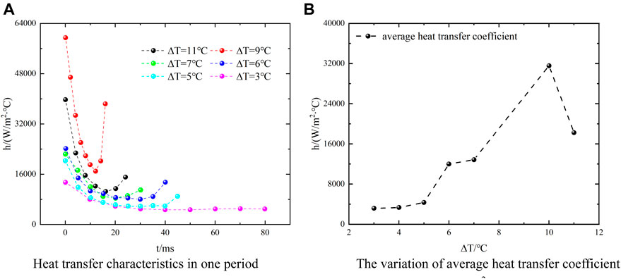
Figure 7. Condensation heat-transfer characteristic curve at Ge = 160 kg/m2∙s. (A) Heat transfer characteristics in one period. (B) The variation of the average heat-transfer coefficient.
Increasing the steam flow rate to 180 kg/m2∙s, as shown in Figure 8, the variation of the heat transfer coefficient in one period is still as same as the condition described previously. When the sub-cooled degree of the ambient water is relatively high, there is a relatively complete cycle process of the growth and collapse of the steam plume, the heat transfer coefficient varies greatly in one plume growth cycle. However, when the sub-cooled degree is low, the cooling capacity of the ambient water becomes weaker, which results in a slight variation in the steam plume shape, and the heat transfer coefficient in its period also varies slightly. The overall trend of the average heat-transfer coefficient decreases gradually with the decrease of the sub-cooled degree, and the slight increase of the heat transfer coefficient at the intermediate temperature is also caused by the oscillation phenomenon of the steam plume shape in one cycle.
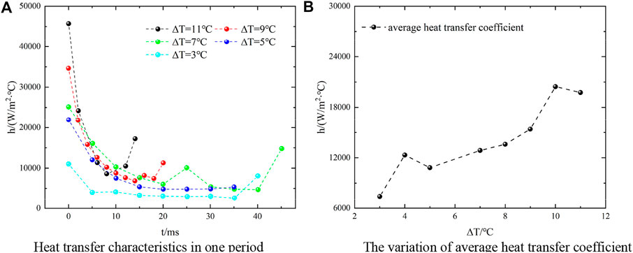
Figure 8. Condensation heat-transfer characteristic curve at Ge = 180 kg/m2∙s. (A) Heat-transfer characteristics in one period. (B) The variation of the average heat-transfer coefficient.
Continuing to increase the steam flow to 200 kg/m2∙s, as shown in Figure 9, the variation of the heat-transfer coefficient and average heat transfer coefficient in one period are basically the same as those of 180 kg/m2∙s. Comparing the heat-transfer coefficients at different flow rates, it can be found that with the increase of steam flow, the overall trend of the average heat-transfer coefficient is to increase gradually with the increase of steam flow rate.
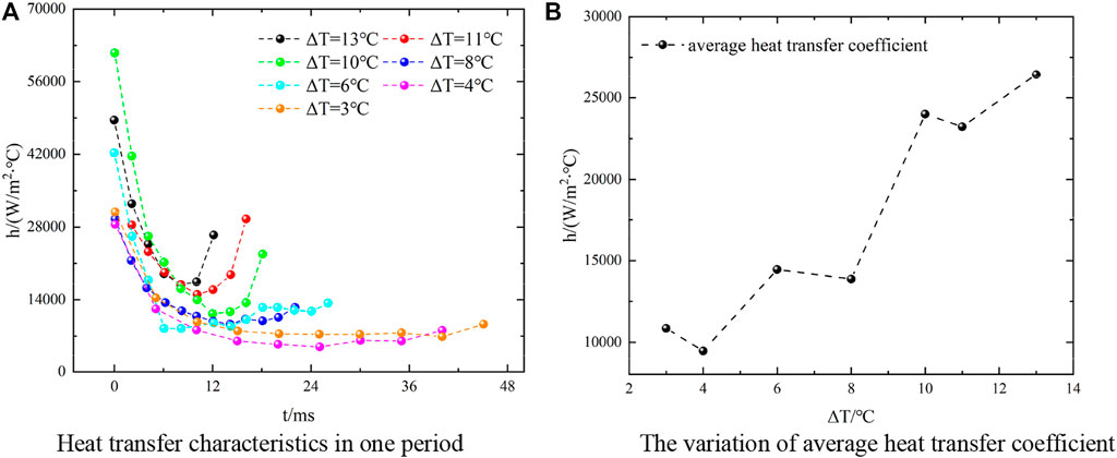
Figure 9. Condensation heat-transfer characteristic curve at Ge = 200 kg/m2∙s. (A) Heat transfer characteristics in one period. (B) The variation of average heat-transfer coefficient.
5 Conclusion
This experimental study, having used visualization technology to capture the injection pattern of steam in low-sub-cooled water, analyzed the condensation heat-transfer characteristics of the direct-contact condensation of steam and obtained the average condensation heat-transfer coefficient in different conditions. The conclusions are as follows:
(1) When the sub-cooled degree of the ambient water remains, the change of the steam flow rate has no obvious influence on the heat transfer capacity in a high sub-cooled degree environment, for example, in a sub-cooled temperature of 11°C, the range of the heat-transfer coefficient varies from 5,737 W/m2∙°C to 45,125 W/m2∙°C, comparing with that of 3°C, which varies from 3,576 W/m2∙°C to 30,998 W/m2∙°C. The trend of the heat-transfer coefficient depends on the relative degree of energy introduced by the steam flow rate and the condensation capacity caused by turbulence;
(2) The increase of steam flow in the low-sub-cooled environment is beneficial for heat exchange. Since the condensation capacity of ambient water is greatly reduced, the turbulence effect caused by the steam jet gradually in a predominant role in depending the heat-transfer coefficient, though the maximum coefficient reduces, the increases have 11,145 W/m2∙°C, in the condition of 3°C sub-cooled temperature;
(3) When the steam flow rate remains, the effect of the ambient water’s sub-cooled degree on the condensation heat-transfer process is certain; that is, with the decrease in the ambient water sub-cooled degree (for example, from 11°C to 3°C), the condensation heat-transfer capacity decreases. However, due to the impact on the steam plume shape, the heat-transfer characteristics at some conditions do not obey the overall trend.
Data availability statement
The original contributions presented in the study are included in the article/Supplementary Material; further inquiries can be directed to the corresponding authors.
Author contributions
CQ: writing—original draft. LH: data curation and methodology. LD, WJ, LY, XQ, and TS: supervision and writing—review and editing.
Funding
This work was financially supported by the Technology Field Fund (2019-JCJQ-JJ-555), Open Fund of Key Laboratory of Thermal Energy and Power Technology (QTWB-2019719-57), and Natural Science Foundation of Heilongjiang Province of China (LH2020E068).
Conflict of interest
The authors declare that the research was conducted in the absence of any commercial or financial relationships that could be construed as a potential conflict of interest.
Publisher’s note
All claims expressed in this article are solely those of the authors and do not necessarily represent those of their affiliated organizations, or those of the publisher, the editors, and the reviewers. Any product that may be evaluated in this article, or claim that may be made by its manufacturer, is not guaranteed or endorsed by the publisher.
References
Chan, C. K., and Lee, C. K. B. (1982). A regime map for direct contact condensation. Int. J. Multiph. Flow 8, 11–20.
Chen, X., Tian, M., Zhang, G., Leng, X., Qiu, Y., and Zhang, J. (2019). Visualization study on direct contact condensation characteristics of sonic steam jet in subcooled water flow in a restricted channel. Int. J. Heat Mass Transf. 145, 118761.
Chun, M. H., Kim, Y. S., and Park, J. W. (1996). An investigation of direct condensation of steam jet in subcooled water. Int. Commun. Heat Mass Transf. 23, 947–958. doi:10.1016/0735-1933(96)00077-2
Cumo, M., Farello, G. E., and Ferrari, G. (1977). Heat transfer in condensing jets of steam in water (pressure-suppressure systems).
Datta, P., Chakravarty, A., Saha, R., Chaudhuri, S., Ghosh, K., Mukhopadhyay, A., et al. (2021). Experimental investigation on the effect of initial pressure conditions during steam-water direct contact condensation in a horizontal pipe geometry. Int. Commun. Heat Mass Transf. 121, 105082. doi:10.1016/j.icheatmasstransfer.2020.105082
de With, A. (2009). Steam plume length diagram for direct contact condensation of steam injected into water. Int. J. Heat Fluid Flow 30, 971–982. doi:10.1016/j.ijheatfluidflow.2009.06.001
Fukuda, S., and Saitoh, S. (1982). Pressure variations due to vapor condensation in liquid, (I) classification of phenomena and study on chugging. Minato-ku, Tokyo: Journal of the Atomic Energy Society of Japan. Available at: https://inis.iaea.org/search/search.aspx?orig_q=rn:53116608.
Gulawani, S. S., Joshi, J. B., Shah, M. S., RamaPrasad, C. S., and Shukla, D. S. (2006). CFD analysis of flow pattern and heat transfer in direct contact steam condensation. Chem. Eng. Sci. 61, 5204–5220. doi:10.1016/j.ces.2006.03.032
Izuo, A., Michiyuki, K., and Hideki, N. (1983). Pressure and fluid oscillations in vent system due to steam condensation, (II). J. Nucl. Sci. Technol. 20, 213–227. doi:10.1080/18811248.1983.9733383
Izuo, A., Nariai, H., and Kobayashi, M. (1980). Pressure and fluid oscillations in vent system due to steam condensation. I. Experimental results and analysis model for chugging. J. Nucl. Sci. Technol.
Kadlec, J., and Müller, R. A. (1976). Dynamic loading of containment during blowdown: Review of experimental data from marviken and brunsbüttel. Nucl. Eng. Des. 38, 143–158. doi:10.1016/0029-5493(76)90092-3
Kwidzinski, R. (2021). Condensation heat and mass transfer in steam–water injectors. Int. J. Heat Mass Transf. 164, 120582. doi:10.1016/j.ijheatmasstransfer.2020.120582
Li, H., Tian, M., Wei, M., and Zhang, J. (2022). Numerical investigation on interfacial characteristics of steam bubble condensation in subcooled water. Int. Commun. Heat Mass Transf. 132, 105886. doi:10.1016/j.icheatmasstransfer.2022.105886
Li, S., Han, W., Lu, T., Feng, L., Hou, N., and Li, T. (2021a). Numerical study on oscillation characteristics of large chugging of direct condensation of steam in a Tee junction with flowing sub-cooled water. Prog. Nucl. Energy 135, 103720. doi:10.1016/j.pnucene.2021.103720
Li, S. Q., Wang, P., and Lu, T. (2015). Numerical simulation of direct contact condensation of subsonic steam injected in a water pool using VOF method and LES turbulence model. Prog. Nucl. Energy 78, 201–215. doi:10.1016/j.pnucene.2014.10.002
Li, W., Meng, Z., Sun, Z., Fan, G., and Wang, J. (2020). Investigation on steam direct contact condensation injected vertically at low mass flux, part II: Steam–air mixture experiment. Int. J. Heat Mass Transf. 155, 119807. doi:10.1016/j.ijheatmasstransfer.2020.119807
Li, W., Wang, J., Zhou, Y., Sun, Z., and Meng, Z. (2019). Investigation on steam contact condensation injected vertically at low mass flux: Part I pure steam experiment. Int. J. Heat Mass Transf. 131, 301–312. doi:10.1016/j.ijheatmasstransfer.2018.11.047
Li, Y., Zhang, D. L., Sun, D. C., Zan, Y. F., Xi, Z., Zhuo, W. B., et al. (2021b). Experimental investigation on steam contact condensation in emergency makeup tank. Nucl. Eng. Des. 384, 111470. doi:10.1016/j.nucengdes.2021.111470
Liu, X., Yu, M., Li, W., Yu, P., Meng, Z., and Sun, Z. (2022). Characteristics of fluid and pressure oscillations induced by steam injected through a vertical blow down pipe under different vessel pressures. Ann. Nucl. Energy 173, 109123. doi:10.1016/j.anucene.2022.109123
Lu, D., Feng, L., Qiu, Z., Liu, L., Chen, J., Fu, J., et al. (2021). Experimental research on the characteristics of steam jet condensation in subcooled water through a double-hole nozzle in one direction. Ann. Nucl. Energy 151, 107898. doi:10.1016/j.anucene.2020.107898
Miwa, S., Xu, Y., Hibiki, T., Sakashita, H., and Sawa, K. (2021). Pressure elevation of high-performance steam-water condensing-injector. Int. J. Heat Mass Transf. 170, 120971. doi:10.1016/j.ijheatmasstransfer.2021.120971
Pesetti, A., Lo Frano, R., and Aquaro, D. (2020). Numerical analysis of sub-atmospheric steam condensation in suppression tank with SIMMER IV code. Fusion Eng. Des. 158, 111746. doi:10.1016/j.fusengdes.2020.111746
Petrovic de With, A., Calay, R. K., and de With, G. (2007). Three-dimensional condensation regime diagram for direct contact condensation of steam injected into water. Int. J. Heat Mass Transf. 50, 1762–1770. doi:10.1016/j.ijheatmasstransfer.2006.10.017
Pttikangas, T., Niemi, J., Laine, J., Puustinen, M., and Purhonen, H. (2010). CFD modelling of condensation of vapour in the pressurized PPOOLEX facility. CFD Nucl. React. Saf. Appl. Workshop 3, CFD4NRS.
Wang, J., Chen, C., Liang, D., Lu, T., and Bai, S. (2021a). Temperature and pressure oscillations induced by steam direct contact condensation in a T-junction with porous inner-structures. Int. J. Heat Mass Transf. 168, 120863. doi:10.1016/j.ijheatmasstransfer.2020.120863
Wang, J., Chen, L., Cai, Q., Hu, C., and Wang, C. (2021b). Direct contact condensation of steam jet in subcooled water: A review. Nucl. Eng. Des. 377, 111142. doi:10.1016/j.nucengdes.2021.111142
Xu, Q., Liang, L., She, Y., Xie, X., and Guo, L. (2022a). Numerical investigation on thermal hydraulic characteristics of steam jet condensation in subcooled water flow in pipes. Int. J. Heat Mass Transf. 184, 122277. doi:10.1016/j.ijheatmasstransfer.2021.122277
Xu, Q., Liu, C., Liu, Q., Zhu, Y., Zhou, H., and Guo, L. (2022b). Interfacial characteristics of steam jet condensation in subcooled water pipe flow – an experimental and numerical study. Chem. Eng. Sci. 251, 117457. doi:10.1016/j.ces.2022.117457
Yang, S. R., Seo, J., and Hassan, Y. A. (2019). Thermal hydraulic characteristics of unstable bubbling of direct contact condensation of steam in subcooled water. Int. J. Heat Mass Transf. 138, 580–596. doi:10.1016/j.ijheatmasstransfer.2019.04.065
Zhou, Y., Yang, X., Fu, P., Liu, J., and Yan, J. (2021). Numerical investigation on submerged steam jet condensation in subcooled water flow in a restricted channel with the presence of non-condensable gas. Int. J. Therm. Sci. 170, 107122. doi:10.1016/j.ijthermalsci.2021.107122
Keywords: direct-contact condensation, low-sub-cooled flow fields, condensation heat transfer coefficient, two-phase flow, plume visualization
Citation: Qian C, Hui L, Dongyang L, Jiming W, Yong L, Qi X and Sichao T (2023) Experimental study on heat transfer characteristics of steam underwater direct-contact condensation. Front. Therm. Eng. 2:1030998. doi: 10.3389/fther.2022.1030998
Received: 29 August 2022; Accepted: 06 December 2022;
Published: 10 January 2023.
Edited by:
Hossain Nemati, Islamic Azad University, Marvdasht, IranReviewed by:
Mehdi Hashemi-Tilehnoee, CIC Energigune, SpainWeixiong Chen, Xi’an Jiaotong University, China
Copyright © 2023 Qian, Hui, Dongyang, Jiming, Yong, Qi and Sichao. This is an open-access article distributed under the terms of the Creative Commons Attribution License (CC BY). The use, distribution or reproduction in other forums is permitted, provided the original author(s) and the copyright owner(s) are credited and that the original publication in this journal is cited, in accordance with accepted academic practice. No use, distribution or reproduction is permitted which does not comply with these terms.
*Correspondence: Wen Jiming, d2VuamltaW5nQGhyYmV1LmVkdS5jbg==; Li Yong, ZW1jcnlAMTYzLmNvbQ==