 Gennifer A. Riley
 Carlos Espino Mendez
 Munonyedi Egbo
 Gisuk Hwang
 Melanie M. Derby
- 1Kansas State University, Alan Levin Department of Mechanical and Nuclear Engineering, Manhattan, KS, United States
- 2Wichita State University, Department of Mechanical Engineering, Wichita, KS, United States
This paper investigates the effects of hemispherical mounds on filmwise condensation heat transfer in micro-channels. Also investigated were the impacts that spatial orientation of the three-sided condensation surface (i.e., gravitational effects) on steam condensation, where the cooled surfaces were either the lower surface (i.e., gravity pulls liquid towards the condensing surfaces) or upper surface (i.e., gravity pulls liquid away from the condensing surfaces). Two test coupons were used with 1.9-mm hydraulic diameters and either a plain copper surface or a copper surface modified with 2-mm diameter hemispherical mounds. Heat transfer coefficients, film visualization, and pressure drop measurements were recorded for both coupons in both orientations at mass fluxes of 50 kg/m2s and 125 kg/m2s. For all test conditions, the mounds were found to increase condensation heat transfer coefficients by at minimum 13% and at maximum 79%. When the test section was inverted (i.e., condensing surface on the top of flowing steam), minimal differences were found in mound performance, while the plain coupon reduces heat transfer coefficients by as much as 14%. Flow visualization suggests that the mounds enhanced heat transfer due to the disruption of the film as well as by reducing the thermal resistance of the film. Pressure drops followed parabolic behavior with quality, being higher in the mound coupon than the plain coupon. No significant pressure drop differences in the inverted orientation were observed.
1 Introduction
Closed-loop thermal management systems utilize their working fluid to remove heat from a source, such as electronics or motors, and reject that heat into a heat sink, such as a radiator (Ho and Leong, 2021). In space, it is particularly important to be able to move the thermal energy since cooling of the entire system is only possible by thermal radiation (Mudawar, 2017). By using a two-phase fluid in the closed-loop, the latent heat of the working fluid can be used advantageously by either evaporating or condensing it, allowing for significant heat transfer without significant temperature gradients in the fluid. For condensation processes, the condensed liquid (i.e., condensate) acts to insulate the cooling surface from the working fluid (Sun and Wang, 2016; Niu et al., 2017; Alizadeh-Birjandi et al., 2019). While condensation can be dropwise or filmwise, filmwise condensation is prevalent in internal flows as it does not require any special coatings or conditions to occur (Ma et al., 2014; Chen and Derby, 2016; Alizadeh-Birjandi et al., 2019). Since the film in filmwise condensation prevents direct heat transfer between the cooling surface and the vapor, heat transfer coefficients tend to be an order of magnitude lower compared to dropwise condensation (Rose, 2002; Orejon et al., 2017; El Fil et al., 2020). As such, when the film is thinner, for example, occurring when the quality is high, heat transfer coefficients increase. Similarly, heat transfer coefficients increase with increasing mass flow rate where convection becomes more significant relative to conductive heat transfer through the film.
In mini-channels, where the hydraulic diameter is between 200 μm and 3 mm and shear forces become dominate, the film wets the entire surface, thins, and forms an annulus of condensate through which the vapor flows (Soliman et al., 1968; Soliman, 1982; Kandlikar and Grande, 2003). Kim and Mudawar (2013) developed a correlation for determining the particular flow regime (i.e., slug or wavy annular) determined by the fluid properties, flow rate, and quality (Kim and Mudawar, 2013). While the thinner film and flow regimes improve heat transfer rates, the decreased diameter increases the pressure drop across the condenser (Kim and Mudawar, 2012). This increased pressure drop requires additional work from the closed-loop compressor or pump, which can negate the positive impact on heat transfer. Therefore, enhancements that increase the heat transfer coefficient without substantially increasing the pressure drop in condensers are of particular interest (Mudawar, 2017).
One approach for enhancing condensation in micro-channels is to coat the surface in hydrophobic substance such as Teflon, which transitions the filmwise condensation into dropwise condensation, resulting in enhancements up to 10 times, yet coatings are not always durable (Miljkovic and Wang, 2013; Chen and Derby, 2016; Chen et al., 2017; Antao et al., 2020; Hoque et al., 2022). However, durable hydrophobic coatings remain an active research area, thus condensation processes in industry are filmwise condensation instead of dropwise condensation (Ahlers et al., 2019; Chang et al., 2020). Another means of condensation heat transfer is to roughen hydrophilic surfaces to decrease the wettability and increase the roughness Reynolds number, in order to increase the heat transfer coefficient (Dipprey and Sabersky, 1963; Nicol and Medwell, 1966; Nguyen and Ahn, 2021).
Other approaches to enhancing filmwise condensation include physically modifying the condensing surface with structures designed to increase condensing surface area, penetrate the film, or disrupt the film by the addition of fins, twisted tape, or corrugation inside of the condensing channel (Cavallini et al., 2003; Dalkilic and Wongwises, 2009; El Kadi et al., 2021). Ho et al. (2019) used conical pin fins in a circular tube and compared them to dome shaped fins evaluated by Wang et al. (2018). Using R134a in 8.7-mm channels, (Ho et al., 2019) determined that helically arranged conical fins could enhance the heat transfer coefficient by up to 2.44 times more than pressure drop was increased (Ho et al., 2019). This increase in heat transfer coefficient enhancement relative to increased pressure was not found to be true of the dome fins used by Wang et al. (2018) also using R134a in 8.7-mm channels (Wang et al., 2018; Ho et al., 2019). Aroonrat and Wongwises (2019) used a 8.1-mm circular channel with R134a where dimples on the exterior of the tube were used to create hollow pin fins with depths of 0.5, 0.75, and 1 mm with diameters of 1, 1.5, and 2 mm, respectively, in the channel. While they were able to increase the heat transfer coefficient by up to 83%, the pressure drop was increased by up to 892% compared to a non-modified channel (Aroonrat and Wongwises, 2019).
Although steam flow condensation has applications in air-cooled condensers and solar energy production, there are limited flow condensation data for condensation of steam in mini-channels (Dirker et al., 2019; El Kadi et al., 2021). Research conducted using fins and other structures to enhance heat transfer properties of steam have largely focused on vertical gravity-driven condensation processes. Winter and McCarthy (2020) used a series of open, parallel amphiphilic channels to promote droplet nucleation in the bottom of the channel while the top of the channel is hydrophobic, cause the droplets to de-wet and be removed from the surface to increase the condensation rate (Winter and McCarthy, 2020; Winter et al., 2021). Modak et al. (2019) performed a numerical analysis and experimentally verified the impacts a monolayer of spherical particles on a vertical condensing plate and found that, depending on the particle size, they will act as either a fin, a wick, or as surface roughness with reductions in thermal resistance occurring for particle diameters between 1 and 50 µm and above 700 µm (Modak et al., 2019). Ho and Leong (2020) studied a vertical plate packed with conical fins to increase the gravity-driven condensation heat transfer coefficient 146% over a plain surface (Ho and Leong, 2020).
While these enhancement methods can be easily used within Earth’s gravity, for microgravity applications, such as satellites or spacecraft, the impacts that gravity has on the condensation process need to be understood. Since performing experiments in micro-gravity settings is time and resource intensive, changing the orientation of test sections so that any gravitational impacts will work with or against the condensation process allows researchers to predict how the process would change in a micro-gravity setting (Mudawar, 2017). As the diameter of a channel decreases, the relative strength of surface tension and shear forces increase relative to gravitational forces (Wen et al., 2018). For low mass velocity flows in particular though, gravitational forces can still distort the shape of the annulus, preventing radial symmetry in horizontal circular channels (Mudawar, 2017). For channels that have neither radial symmetry nor condensation on all surfaces, such as the channels investigated in this paper, there is little information available regarding the effects of channel orientation on the condensation properties of the channel.
The objectives of this study are to investigate the impacts of hemispherical structures in rectangular mini-channels on liquid film thickness and its impacts on heat transfer during flow condensation. Observations were made by measuring the heat transfer, pressure drop, and visualizing the condensate film. Additionally, this study examines the effects of gravity on the horizontal two-phase flows by changing the orientation of the test section such that condensation would either occur on the lower or upper surface of the channel.
2 Materials and methods
2.1 Experimental apparatus
Experiments were conducted using an open-loop steam apparatus, shown in Figure 1, designed to measure condensation heat transfer coefficients, pressure drops and allow for visualization of the condensation process. Steam is regulated to 250 kPa for all test conditions and passes through a separator to remove any water and a filter system to remove any contaminates which may be in the steam supply. Due to uncertainty regarding the initial steam quality, the steam is superheated by 20–30°C. The superheated steam then passes through a pre-condenser to control the quality of the steam entering the test section. The cooling water is supplied by a constant-temperature bath (Neslab RTE-221), its mass flow rate measured via a Coriolis flow meter (CMFS015M, Micro Motion), and its temperature is measured by two T-type thermocouples.
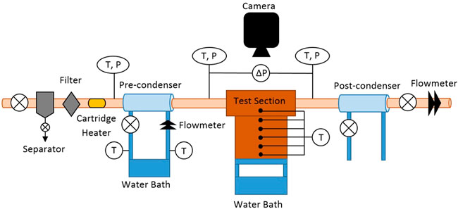
Figure 1. Open-loop experimental apparatus for steam condensation heat transfer and simultaneous flow visualization.
The steam temperature was measured before and after the pre-condenser using T-type thermocouples (Omega; T-Q-SS-116-G-3) and as well as after passing through the test section. A differential pressure transducer (Omega; PX409) was used to measure the pressure drop in the test section. Five T-type thermocouples (Omega; TJC36-CPSS-062U-2) installed in the cooling block were used to calculate the heat flux leaving the steam and entering cooling water supplied by a second constant-temperature bath. A sixth T-type thermocouple in the test coupon was used to determine the wall temperature in the channel. To test the effects of gravity on flow condensation, the same apparatus was used where the test section was inverted such that the cooling surface was above the steam flow as seen in Figure 2. In both orientations, visualization of the film was conducted using Leica Z16 APO macroscope and a FASTEC IL3 high-speed camera. Temperature and pressure data were collected using LabVIEW and a cDAQ-9174 with NI TB-9214 and NI 9207 modules.
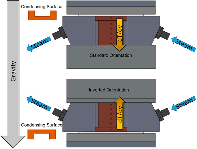
Figure 2. Test section, including coupons and heat flux block, where (above) the test section is in the standard orientation with the cooled surfaces were the lower surfaces (i.e., gravity pulls liquid towards the condensing surfaces) or (below) the test section was inverted such that the cooled surfaces were the upper surfaces (i.e., gravity pulls liquid away from the condensing surfaces).
Two test coupons, shown in Figure 3, were constructed out of oxygen-free copper and with a channel whose hydraulic diameter was 1.9 mm. The first coupon had a channel with a flat rectangular cross section and no additional structures added. The second test section had copper hemispheres added via the following process. The physical and chemical contaminations on the copper coupon surface were removed by using acetone, and then dried under ambient conditions. The 2-mm copper balls were then placed in the hemi-spherical, pre-machined grooves in the channel of the coupon. A stainless-steel mold with the same hemi-spherical groove pattern was placed over the copper balls with a light pressure to secure the copper balls in place. Note that the stainless-steel mold was coated with carbon powder to prevent from sintering the copper balls and the mold. The copper coupon with the copper balls and the stainless-steel mold was then placed in a tube furnace (OTF-1200X) for sintering. The temperature of the furnace during the sintering process was controlled with respect to time as shown in Figure 4; the peak temperature used in this study was 1,000°C. To avoid possible mechanical damage due to sudden heating and cooling, the furnace heated and cooled at 3–5°C/min with constant temperature periods of 10–20 min between each temperature increase or decrease. At the end of the sintering process, the stainless-steel mold was mechanically removed, leaving only the sintered copper balls on the coupon. For the mound coupon, the hydraulic diameter was calculated by using the length averaged cross-sectional area and perimeter.
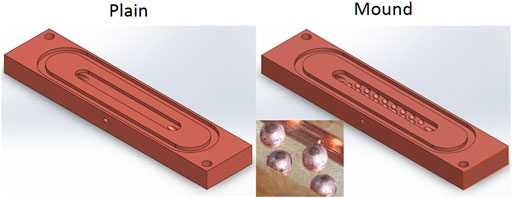
Figure 3. Coupons with 1.9-mm hydraulic diameters; (left) plain coupon with no additional structures and (right) coupon with 2-mm-diameter mound structures.
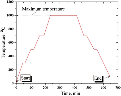
Figure 4. The sintering temperature as a function of time with the peak temperature shown.
2.2 Data Reduction
Heat transfer coefficients, h, were calculated using Fourier’s Law to determine the heat transfer rate through the copper block,
2.3 Uncertainties
All measurement devices were calibrated. The T-type thermocouples were calibrated in a water bath at 5°C increments from 5°C to 60°C, as well as in boiling water and in an ice bath, and compared against a reference thermometer, resulting in a thermocouple uncertainty of ±0.2°C. For the temperature gradient from the test section, the uncertainty was calculated using the following equation (Kedzierski and Worthington, 1993).
where Dhole is the diameter of the thermocouple hole, q” is the heat flux, y is the position of each hole along the direction of the thermal gradient,
where the uncertainties were dependent on uncertainties in the block heat transfer rate,
3 Results and discussion
3.1 Single-phase validation
To validate heat transfer measurements, steam was cooled to subcooled water at 250 kPa and 50°C to 70°C for a single-phase validation using the plain coupon. This validation used two metrics, the first was to compare the amount of energy which was exiting the water,
where
The second validation compared measured Nusselt numbers to the correlation made by Muzychka and Yovanovich (2004) for non-circular ducts, which provides an upper and lower bound for the single-phase Nusselt number (Muzychka and Yovanovich, 2004),
where the values of c1, c2, c3, c4, and f(Pr) are determined by the boundary conditions, ε is the aspect ratio of the channel, and γ is the shape parameter which is 1/10 for the upper bound and −3/10 for the lower bound. Additionally, f(Pr), f(Re), and Nu are the functions for the Prandtl number, Reynolds number, and Nusselt number, respectively. The energy transfer from the subcooled water to the cooling block was within 20% for all experimental points. Additionally, all Nusselt numbers were within or within the error of the predicted value range, as shown in Figure 5. The energy balance and Nusselt number analysis confirmed that the apparatus operated as predicted and that two-phase heat transfer measurements are accurate.
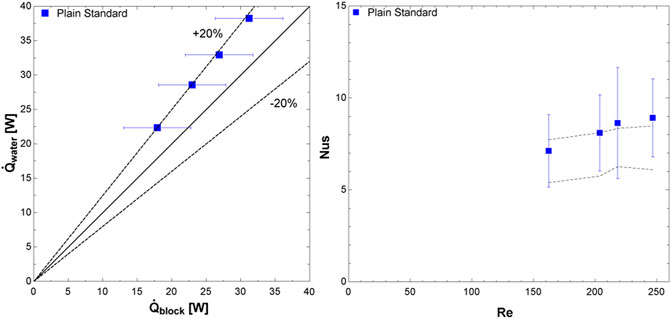
Figure 5. Single phase validation, including (left) energy balance and (right) measured Nusselt numbers compared to predictions by the single-phase Muzychka and Yovanovich (2004) correlation.
3.2 Flow condensation heat transfer coefficients
Data collected from the plain coupon, in the standard orientation (i.e., condensation on lower surface), served as a baseline to compare against for any enhancement. For a mass flux of 50 kg/m2s and qualities from 0.20 to 0.87, the flow condensation heat transfer coefficients range from 22,200 W/m2K to 53,000 W/m2K. At the mass flux of 125 kg/m2s and qualities from 0.33 to 0.97, the flow condensation heat transfer coefficients ranged from 40,800 W/m2K to 95,200 W/m2K. For both mass fluxes, the heat transfer coefficients nearly linearly increased with quality; similarly, the heat transfer coefficients are higher with the increased mass flux. To compare the other coupon and inverted test section orientations, a third-degree polynomial was curve fit to these measured heat transfer coefficients so that an enhancement factor could be calculated for any quality. The R2 values for these were 0.9908–0.9986 for the 50 kg/m2s and 125 kg/m2s data sets, respectively. Heat transfer coefficients for all experiments are shown in Figure 6 and condensation heat transfer enhancements in Figure 7. The two-phase heat transfer coefficients for the plain coupon in the standard configuration (i.e., experiencing lower surface condensation) were compared to the values predicted by the Kim and Mudawar (2013) correlation for condensing in mini/micro channels (Kim and Mudawar, 2013) in order to compare to other experimental values obtained in similar channels. The Mean Absolute Percentage Error (MAPE) for a mass flux of 50 kg/m2s was 38% and for a mass flux of 125 kg/m2s was 16%, as shown in Figure 8,
where hpred is the heat transfer coefficient predicted by the correlation, and hexp is the observed heat transfer coefficient from the experimental apparatus. Since the flow regimes (Section 3.3) influence the predicted heat transfer coefficients, it should be noted that for the mass flux of 50 kg/m2s, the flow regimes predicted by the Kim and Mudawar (2013) correlation were all either in the transitional or slug regimes, while for a mass flux of 125 kg/m2s, the predicted flow regimes were either wavy-annular or transitional.
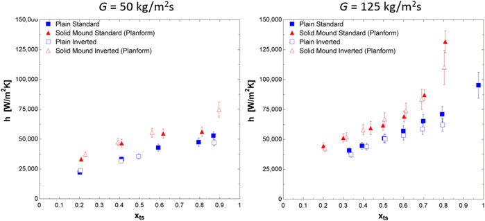
Figure 6. Flow condensation heat transfer coefficients, for (left) a mass flux of 50 kg/m2s and (right) a mass flux of 125 kg/m2s.
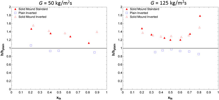
Figure 7. Heat transfer coefficient enhancement for the plain coupon in the inverted orientation and the mound coupon in the standard and inverted orientations compared to the plain coupon in the standard orientation (left) for a mass flux of 50 kg/m2s and (right) a mass flux of 125 kg/m2s.
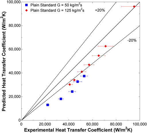
Figure 8. Flow condensation heat transfer coefficients predicted by the Kim and Mudawar (2013) model for the plain coupon in standard orientation.
For the mound coupon, condensation heat transfer coefficients were calculated using its planform area, though the actual surface area of the mound coupon is 13.8% larger than that of the plain coupon. With a mass flux of 50 kg/m2K and qualities from 0.21 to 0.81, the heat transfer coefficients ranged from 33,100 W/m2K to 56,200 W/m2K. This corresponds to a linearly decreasing enhancement of 47% at a quality of 0.21%, to a 13% enhancement at a quality of 0.81. At a mass flux of 125 kg/m2s, the heat transfer coefficients range from 44,300 W/m2K to 132,000 W/m2K at qualities of 0.20–0.81, respectively. The enhancement has a generally parabolic shape as a function of quality where the greatest enhancement occurring at the low and high quality points. At a quality of 0.20, the heat transfer coefficient is enhanced 48%, and at a quality of 0.81, it is enhanced by 79%. The lowest enhancement occurs at a quality of 0.5 and corresponds to an enhancement of 20%. This parabolic enhancement trend is best explained by the relative size of the mounds to the film as well as the disruption of film flow which occurred due to them, as discussed in Section 3.3. These heat transfer enhancements are similar to those found in by Aroonrat and Wongwises (2019), using R134a, with hollow pin fins with a maximum increase of 83% (Aroonrat and Wongwises, 2019), although this enhancement is smaller than the 244% enhancement measured by (Ho et al., 2019) using R134a with conical fins lining the interior of the channel (Ho et al., 2019). Ho and Leong (2020) investigated condensing steam on vertical plates with an array of conical films, which resulted in an increase of 146%; however, this differs from the present study as Ho and Leong (2020) studied gravity-driven film condensation (Ho and Leong, 2020).
Flow condensation data for the inverted test sections, where condensation occurred on the upper surface, had similar results to that of the standard test sections. For the plain inverted test section, at a mass flux of 50 kg/m2s, heat transfer coefficients ranged from 23,700 W/m2K to 47,000 W/m2K at qualities from 0.20 to 0.87, which corresponded to an increase of 6.8% and a decrease of 10% in heat transfer coefficients, respectively. At a mass flux of 125 kg/m2s, the plain inverted test section had heat transfer coefficients from 37,300 W/m2K to 62,000 W/m2K at qualities from 0.34 to 0.79. In this case there was no heat transfer enhancement, with a decrease in performance of 9.5% at a quality of 0.34 to a decrease of 14% at a quality of 0.79. The minimum decrease in heat transfer coefficient was 2.2% and occurred at a quality of 0.51. For the inverted plain test section, all decreases in heat transfer coefficient were less than 10%.
For the inverted mound test sections at a mass flux of 50 kg/m2s, heat transfer coefficients ranged from 37,300 W/m2K to 74,800 W/m2K at qualities of 0.23–0.90 respectively with corresponding enhancements of 56%–40% with a low of 37% occurring at a quality of 0.56. With a mass flux of 125 kg/m2s, the heat transfer coefficients went from 42,300 W/m2K to 110,000 W/m2K at qualities from 0.21 to 0.80. As with the standard orientation, the enhancement was parabolic with an enhancement of 38% at quality of 0.21 and 51% at a quality of 0.80. The lowest enhancement was 27% and occurred at a quality of 0.61.
3.3 Flow visualization and condensate film disruption
By using a high-speed camera, the flow condensation was observed at 500 frames per second. In the plain coupon, condensate film flow was generally smooth for both mass fluxes observed. At the lower mass flux and low qualities, the film had almost no disturbances apart from the occasional “wave” across the entire micro-channel. As the quality or flow rate increased, the shear forces from the vapor phase caused consisted small waves to form at the interface between the two phases. For the mound test section, the mounds themselves served to disrupt the flow by preventing the film from flowing in a straight line down the test section. Figure 9 shows the condensed film in both channels at a quality of 0.6 for both mass flow rates. Film disruptions, particularly at the downstream side of the mounds, were common and condensate was also observed to flow over the mounds as shown in Figure 10.
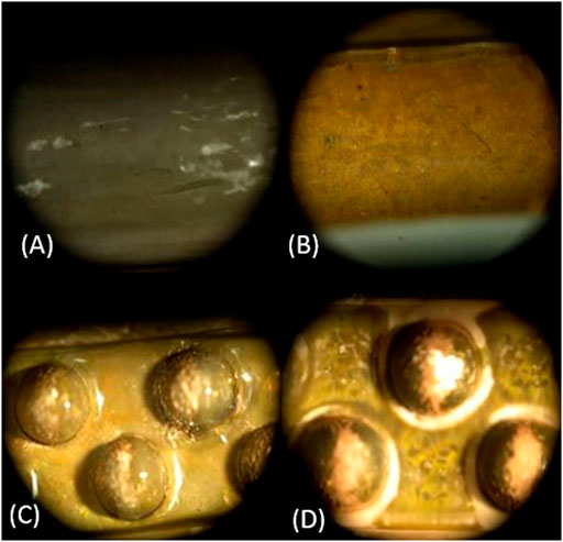
Figure 9. Condensed film in standard plain and mound coupons, (A) plain coupon with a mass flux of 50 kg/m2s, (B) plain coupon with a mass flux of 125 kg/m2s, (C) mound coupon with a mass flux of 50 kg/m2s, (D) mound coupon with a mass flux of 125 kg/m2s; quality is 0.6 for all cases.
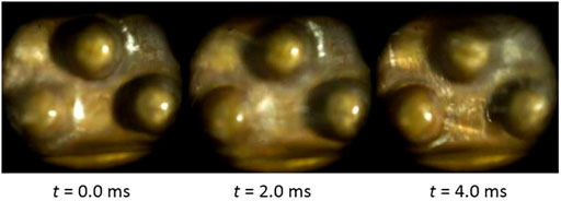
Figure 10. Mound disruption of film at (Left) t = 0 ms, (Middle) t = 2.0 ms, and (Right), t = 4.0 ms at a mass flux of 50 kg/m2s and a quality of 0.2.
To show the significance of the mounds, a maximum film depth was calculated using the Butterworth correlation to estimate the amount of condensed water available for the film (Butterworth, 1975). Figure 11 shows the maximum depth that the film could reach (i.e., estimated film thickness),
where dfilm is the maximum possible film depth, dchannel is the depth of the channel, α is the volumetric fraction of vapor in the channel,
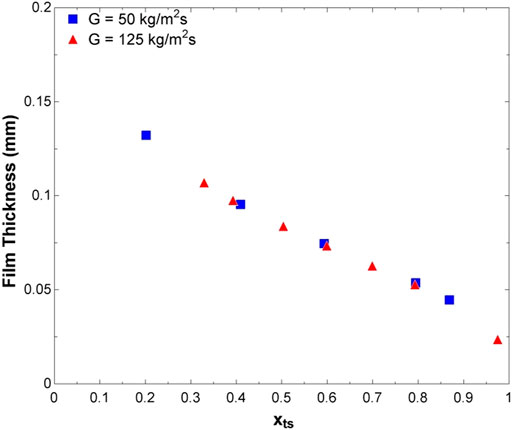
Figure 11. Predicted maximum liquid film thickness using the Butterworth (1975) void fraction model.
In the plain coupon, the thermal resistance is inversely related to the film depth; however, relative to that film depth, the mounds’ 1-mm radius proves a significant obstacle to the flow. For low qualities where the film is thickest, x < 0.4, these disruptions in the film reduce the film thermal resistance by forcing the flow to either pass over or around the mounds, increasing velocity, and decreasing the relative thickness of film. For higher qualities, x > 0.6, the film is thin enough for the mounds to have direct contact with the vapor, allowing them to act like fins, thereby increasing the condensing surface area and increasing the planform heat transfer coefficient in addition to the film disruptions. For all qualities both the film disruptions and fin effects occur; however, they are most dominate for low and high quality respectively which is why for midrange qualities, 0.4 ≤ x ≤ 0.6 the lowest enhancement occurs. Based on the liquid film disruptions observed, it stands to reason that there is some optimal grouping of mounds. If the mounds are too far apart, the opportunity for condensation enhancement via film disruption and fin area is missed. However, if the fins are grouped too closely, such as in a hexagonal close pack, the film may thicken due a smaller effective channel width and the film could also stagnant at the bottom of the channel where the mounds meet, preventing convective heat transfer from locally dominating over conductive heat transfer.
For both coupons, the inversion of the test section had little visual effect on the film, which continued to flow in contact with the cooling surface despite that being the upper side of the flow channel. Heat transfer performance was not significantly impacted by gravity and thus, two nondimensional numbers were evaluated. The Eötvös number, Eo, which represents the ratio of gravitational to surface tension forces, was calculated (Kim and Mudawar, 2012),
where g is the gravity constant, Dh is the hydraulic diameter, and σ is the surface tension.
The Eotvos number was 0.64–0.60 for the plain and mound coupons, respectively. Eötvös numbers less than one support that gravitation forces are not dominant in these coupons. The modified Weber number, We*, which represents the ratio of inertial to surface tension forces, was employed to determine the expected flow regime for each data point (Kim and Mudawar, 2012),
where Reg is the Reynolds number of the gas phase, Sug is the Suratman number of the gas phase, G is the mass flux of steam, and Xtt is the Lockhart-Martinelli parameter. These results can be seen in Figure 12 and shows the flow regimes expected by either slug flow, transitional (between slug and annular), or wavy-annular flow; few data are in the slug flow regime. This supports the observed behavior for the film to adhere to the copper surface regardless of orientation as for these flow regimes the film wet the entire channel surface.
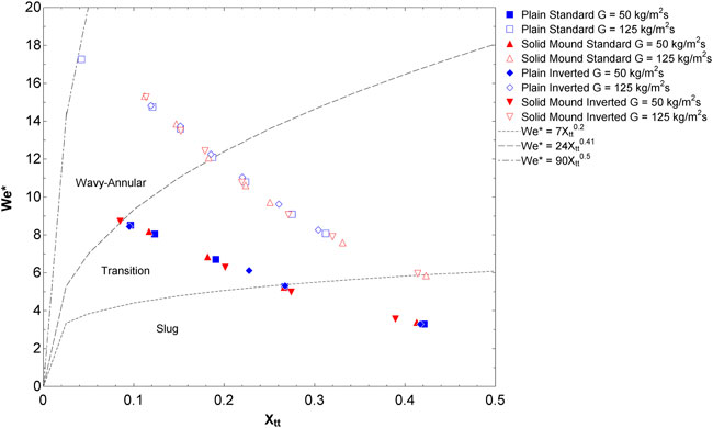
Figure 12. Flow regimes predicted by Kim and Mudawar (2012) for the experimental conditions; most data are in the transition or wavy-annular regimes.
3.4 Pressure drops
Pressure drops were parabolic for both coupons and orientations and were increased with quality and mass flow rate. The pressure drops in the mound coupon were also higher; however, changing the orientation of the test section had minimal impacts, as shown in Figure 13. For the plain coupon with a mass flux of 50 kg/m2s, the pressure drops ranged from 1.8 to 8.8 kPa for qualities from 0.20 to 0.87. At a mass flux of 125 kg/m2s, the pressure drops ranged from 15 to 92 kPa for qualities from 0.33 to 0.97. When the test section was inverted, at the mass flux of 50 kg/m2s pressure drops went from 1.8 to 9.9 kPa for qualities from 0.20 to 0.87 and from 16 to 67 kPa for qualities from 0.34 to 0.79. The standard mound coupon at 50 kg/m2s had pressure drops from 1.2 to 9.2 kPa for qualities from 0.21 to 0.81. At a mass flux of 125 kg/m2s pressure drops ranged from 10 to 110 kPa for qualities from 0.20 to 0.81. For the inverted mound coupon at 50 kg/m2s pressure drops ranged from 3.1 to 18 kPa for qualities from 0.23 to 0.90 and at a mass flux of 125 kg/m2s the pressure drops were from 11 to 120 kPa for qualities from 0.21 to 0.80. The increase in pressure drop was significantly lower than that observed by Aroonrat and Wongwise (2019), using R134a, where the presence of hollow pin fins increased the pressure drop by as 251%, 578%, and 892% depending on the pin fin size of 0.5, 0.75, and 1.0 mm, respectively, with a mass flux of 300 kg/m2s (Aroonrat and Wongwises, 2019). The much lower pressure drop observed in the mound coupon in this study is likely due to the lower frequency and positioning of mounds not constricting the flow through channel as much as pin fins, as well as the lower mass fluxes of 50 kg/m2s and 125 kg/m2s.
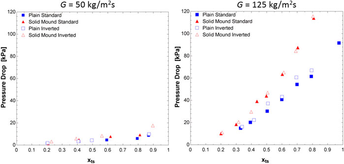
Figure 13. Pressure drops for plain and mound coupons in both orientations (left) for a mass flux of 50 kg/m2s and (right) a mass flux of 125 kg/m2s.
4 Conclusion
Filmwise condensation experiments were conducted on two 1.9-mm-hydraulic-diameter copper coupons. One coupon was a plain rectangular channel while the other was modified with a staggered line of 2-mm-diameter copper hemispheres. Heat transfer measurements, film visualization, and pressure drop data were recorded for steam condensation for two mass fluxes, 50 kg/m2s and 125 kg/m2s, and qualities from 0.20 to 0.97. From this, the following conclusions may be drawn:
• The addition of copper hemispheres increased the heat transfer coefficient by as much as 79%, and which exceeded the area enhancement ratio of 14%.
• The presence of the mounds disrupted the condensate film, preventing the film from flowing as a smooth laminar sheet.
• The height of the mounds was significant compared to the maximum film depth for all tested cases and provided and lowered the effect thermal resistance of the condensate film.
• Changing the orientation of the test section had little effect in the mound coupon and no more than a 14% reduction in heat transfer coefficient in the plain coupon.
• Pressure drops were higher in the mound coupon but were not significantly affected by the change in orientation.
• Future work should include a focus on the placement and frequency of mounds in the channel to enhance filmwise flow condensation heat transfer.
Data availability statement
The raw data supporting the conclusion of this article will be made available by the authors, without undue reservation.
Author contributions
GR, ME, GH, and MD contributed to the design of the study. GR and CM performed the experiments and performed data analysis. GR wrote the manuscript draft. MD and GH revised the manuscript.
Funding
The authors gratefully acknowledge the financial support of NASA Cooperative Agreement Notice, Grant Number 80NSSC18M0030 (primary support of the project), NSF Grant Number 1651451 (support for GAR), and the Developing Scholars Program at KSU (support for CEM).
Conflict of interest
The authors declare that the research was conducted in the absence of any commercial or financial relationships that could be construed as a potential conflict of interest.
Publisher’s note
All claims expressed in this article are solely those of the authors and do not necessarily represent those of their affiliated organizations, or those of the publisher, the editors and the reviewers. Any product that may be evaluated in this article, or claim that may be made by its manufacturer, is not guaranteed or endorsed by the publisher.
Supplementary Material
The Supplementary Material for this article can be found online at: https://www.frontiersin.org/articles/10.3389/fther.2022.953051/full#supplementary-material
References
Ahlers, M., Buck-Emden, A., and Bart, H.-J. (2019). Is dropwise condensation feasible? A review on surface modifications for continuous dropwise condensation and a profitability analysis. J. Adv. Res. 16, 1–13. doi:10.1016/j.jare.2018.11.004
Alizadeh-Birjandi, E., Alshehri, A., and Kavehpour, H. P. (2019). Condensation on surfaces with biphilic topography: Experiment and modeling. Front. Mech. Eng. 5, 38. doi:10.3389/fmech.2019.00038
Antao, D. S., Wilke, K. L., Sack, J. H., Xu, Z., Preston, D. J., and Wang, E. N. (2020). Jumping droplet condensation in internal convective vapor flow. Int. J. Heat Mass Transf. 163, 120398. doi:10.1016/j.ijheatmasstransfer.2020.120398
Aroonrat, K., and Wongwises, S. (2019). Experimental investigation of condensation heat transfer and pressure drop of R-134a flowing inside dimpled tubes with different dimpled depths. Int. J. Heat Mass Transf. 128, 783–793. doi:10.1016/j.ijheatmasstransfer.2018.09.039
Butterworth, D. (1975). A comparison of some void-fraction relationships for co-current gas-liquid flow. Int. J. Multiph. Flow 1 (6), 845–850. doi:10.1016/0301-9322(75)90038-5
Cavallini, A., Censi, G., Del Col, D., Doretti, L., Longo, G., Rossetto, L., et al. (2003). Condensation inside and outside smooth and enhanced tubes—A review of recent research. Int. J. Refrig. 26 (4), 373–392. doi:10.1016/s0140-7007(02)00150-0
Chang, H. C., Rajagopal, M. C., Hoque, M. J., Oh, J., Li, L., Li, J., et al. (2020). Composite structured surfaces for durable dropwise condensation. Int. J. Heat Mass Transf. 156, 119890. doi:10.1016/j.ijheatmasstransfer.2020.119890
Chen, X., and Derby, M. M. (2016). Combined visualization and heat transfer measurements for steam flow condensation in hydrophilic and hydrophobic mini-gaps. J. Heat Transf. 138 (9), 091503-1–091503-11. doi:10.1115/1.4033496
Chen, X., Morrow, J. A., and Derby, M. M. (2017). Mini-channel flow condensation enhancement through hydrophobicity in the presence of noncondensable gas. Int. J. Heat Mass Transf. 115, 11–18. doi:10.1016/j.ijheatmasstransfer.2017.07.029
Dalkilic, A. S., and Wongwises, S. (2009). Intensive literature review of condensation inside smooth and enhanced tubes. Int. J. Heat Mass Transf. 52 (15-16), 3409–3426. doi:10.1016/j.ijheatmasstransfer.2009.01.011
Dipprey, D. F., and Sabersky, R. H. (1963). Heat and momentum transfer in smooth and rough tubes at various Prandtl numbers. Int. J. Heat Mass Transf. 6 (5), 329–353. doi:10.1016/0017-9310(63)90097-8
Dirker, J., Juggurnath, D., Kaya, A., Osowade, E. A., Simpson, M., Lecompte, S., et al. (2019). Thermal energy processes in direct steam generation solar systems: Boiling, condensation and energy storage–A review. Front. Energy Res. 6, 147. doi:10.3389/fenrg.2018.00147
El Fil, B., Kini, G., and Garimella, S. (2020). A review of dropwise condensation: Theory, modeling, experiments, and applications. Int. J. Heat Mass Transf. 160, 120172. doi:10.1016/j.ijheatmasstransfer.2020.120172
El Kadi, K., Alnaimat, F., and Sherif, S. (2021). Recent advances in condensation heat transfer in mini and micro channels: A comprehensive review. Appl. Therm. Eng. 197, 117412. doi:10.1016/j.applthermaleng.2021.117412
Ho, J., and Leong, K. (2021). A critical review of filmwise natural and forced convection condensation on enhanced surfaces. Appl. Therm. Eng. 186, 116437. doi:10.1016/j.applthermaleng.2020.116437
Ho, J., and Leong, K. (2020). Effect of fin pitch on the filmwise condensation of steam on three-dimensional conical pin fin arrays: A comparative study. Int. J. Heat Mass Transf. 150, 119328. doi:10.1016/j.ijheatmasstransfer.2020.119328
Ho, J., Leong, K., and Wong, T. (2019). Forced convection condensation of R134a in three-dimensional conical pin fin tubes. Int. J. Heat Mass Transf. 144, 118599. doi:10.1016/j.ijheatmasstransfer.2019.118599
Hoque, M. J., Chavan, S., Lundy, R., Li, L., Ma, J., Yan, X., et al. (2022). Biphilic jumping-droplet condensation. Cell Rep. Phys. Sci. 3 (4), 100823. doi:10.1016/j.xcrp.2022.100823
Kandlikar, S. G., and Grande, W. J. (2003). Evolution of microchannel flow passages--thermohydraulic performance and fabrication technology. Heat. Transf. Eng. 24 (1), 3–17. doi:10.1080/01457630304040
Kedzierski, M., and Worthington, J. (1993). Design and machining of copper specimens with micro holes for accurate heat transfer measurements. Exp. Heat. Transf. 6 (4), 329–344. doi:10.1080/08916159308946463
Kim, S.-M., and Mudawar, I. (2013). Universal approach to predicting heat transfer coefficient for condensing mini/micro-channel flow. Int. J. Heat Mass Transf. 56 (1-2), 238–250. doi:10.1016/j.ijheatmasstransfer.2012.09.032
Kim, S.-M., and Mudawar, I. (2012). Universal approach to predicting two-phase frictional pressure drop for adiabatic and condensing mini/micro-channel flows. Int. J. Heat Mass Transf. 55 (11-12), 3246–3261. doi:10.1016/j.ijheatmasstransfer.2012.02.047
Ma, X., Wang, S., Lan, Z., Wang, A., and Peng, B. (2014). “Dropwise condensation heat transfer on superhydrophobic surface in the presence of non-condensable gas,” in Proceedings of the 14th International Heat Transfer Conference. Washington, DC: AMSE, 71–79.
Miljkovic, N., and Wang, E. N. (2013). Condensation heat transfer on superhydrophobic surfaces. MRS Bull. 38 (5), 397–406. doi:10.1557/mrs.2013.103
Modak, S., Kaviany, M., Hoenig, S., and Bonner, R. (2019). Numerical analysis of meniscus dynamics in monolayer-wick dropwise condensation. Numer. Heat. Transf. Part A Appl. 76, 301–322. doi:10.1080/10407782.2019.1627829
Mudawar, I. (2017). Flow boiling and flow condensation in reduced gravity. Adv. Heat Transf. 49, 225–306. doi:10.1016/bs.aiht.2017.06.002
Muzychka, Y., and Yovanovich, M. (2004). Laminar forced convection heat transfer in the combined entry region of non-circular ducts. J. Heat. Transf. 126 (1), 54–61. doi:10.1115/1.1643752
Nguyen, D. H., and Ahn, H. S. (2021). A comprehensive review on micro/nanoscale surface modification techniques for heat transfer enhancement in heat exchanger. Int. J. Heat Mass Transf. 178, 121601. doi:10.1016/j.ijheatmasstransfer.2021.121601
Nicol, A., and Medwell, J. (1966). The effect of surface roughness on condensing steam. Can. J. Chem. Eng. 44 (3), 170–173. doi:10.1002/cjce.5450440309
Niu, D., Guo, L., Hu, H., and Tang, G. (2017). Dropwise condensation heat transfer model considering the liquid-solid interfacial thermal resistance. Int. J. Heat Mass Transf. 112, 333–342. doi:10.1016/j.ijheatmasstransfer.2017.04.061
Orejon, D., Shardt, O., Gunda, N. S. K., Ikuta, T., Takahashi, K., Takata, Y., et al. (2017). Simultaneous dropwise and filmwise condensation on hydrophilic microstructured surfaces. Int. J. Heat Mass Transf. 114, 187–197. doi:10.1016/j.ijheatmasstransfer.2017.06.023
Rose, J. (2002). Dropwise condensation theory and experiment: A review. Proc. Institution Mech. Eng. Part A J. Power Energy 216 (2), 115–128. doi:10.1243/09576500260049034
Soliman, H. (1982). On the annular-to-wavy flow pattern transition during condensation inside horizontal tubes. Can. J. Chem. Eng. 60 (4), 475–481. doi:10.1002/cjce.5450600405
Soliman, M., Schuster, J., and Berenson, P. (1968). A general heat transfer correlation for annular flow condensation. J. Heat. Transf. 90 (2), 267–274. doi:10.1115/1.3597497
Sun, J., and Wang, H. S. (2016). On the early and developed stages of surface condensation: Competition mechanism between interfacial and condensate bulk thermal resistances. Sci. Rep. 6 (1), 35003–35012. doi:10.1038/srep35003
Wang, X., Ho, J. Y., Leong, K. C., and Wong, T. N. (2018). Condensation heat transfer and pressure drop characteristics of R-134a in horizontal smooth tubes and enhanced tubes fabricated by selective laser melting. Int. J. Heat Mass Transf. 126, 949–962. doi:10.1016/j.ijheatmasstransfer.2018.04.163
Wen, J., Gu, X., Liu, Y., Wang, S., and Li, Y. (2018). Effect of surface tension, gravity and turbulence on condensation patterns of R1234ze (E) in horizontal mini/macro-channels. Int. J. Heat Mass Transf. 125, 153–170. doi:10.1016/j.ijheatmasstransfer.2018.04.039
Winter, R. L., and McCarthy, M. (2020). Dewetting from amphiphilic minichannel surfaces during condensation. ACS Appl. Mat. Interfaces 12 (6), 7815–7825. doi:10.1021/acsami.9b21265
Keywords: microgravity, gravity, filmwise, heat transfer, mini-channel, two-phase flow
Citation: Riley GA, Mendez CE, Egbo M, Hwang G and Derby MM (2022) Visualizing and disrupting liquid films for filmwise flow condensation in horizontal minichannels. Front. Therm. Eng. 2:953051. doi: 10.3389/fther.2022.953051
Received: 25 May 2022; Accepted: 10 August 2022;
Published: 02 September 2022.
Edited by:
Junming Zhao, Harbin Institute of Technology, ChinaReviewed by:
Shangchao Lin, Shanghai Jiao Tong University, ChinaKang Luo, Harbin Institute of Technology, China
Copyright © 2022 Riley, Mendez, Egbo, Hwang and Derby. This is an open-access article distributed under the terms of the Creative Commons Attribution License (CC BY). The use, distribution or reproduction in other forums is permitted, provided the original author(s) and the copyright owner(s) are credited and that the original publication in this journal is cited, in accordance with accepted academic practice. No use, distribution or reproduction is permitted which does not comply with these terms.
*Correspondence: Melanie M. Derby, ZGVyYnltQGtzdS5lZHU=