 Ruisong Wang
 Dion S. Antao
- 1J. Mike Walker ‘66 Department of Mechanical Engineering, Texas A&M University, College Station, TX, United States
Sustainably enhancing condensation heat transfer performance is a major challenge in thermal management and energy systems, since typical condensation enhancement methods (i.e., dropwise condensation with low surface energy coatings) have limited lifetime/durability, restricted compatibility with working fluids, and sustainability concerns due to the coating composition (e.g., fluorinated compounds). The robust and scalable capillary-enhanced filmwise condensation mode presented in this work demonstrates high heat transfer coefficients for water and low surface tension liquids condensing in a porous wick. Thin porous wicks offer the highest enhancements in heat transfer, however such thin porous wicks have thickness-dependent permeability, and the effective liquid thickness of the wick depends on the shape of the liquid-vapor interface. In this study, we leverage a spatially-discretized porous media model to characterize the effect of the wick thickness on condensation heat transfer performance. The model uses a spatially-varying permeability that depends on the local liquid-vapor interface shape/curvature and the resulting effective wick thickness. We apply this model to investigate the correlation between the heat transfer enhancement and various geometric factors, which enables the design of optimal porous structures for relevant phase-change application. We also predict favorable enhancement in condensation performance with a few common hydrocarbon and fluorocarbon fluid refrigerants. This study provides fundamental insight into the effects of the shape of the liquid-vapor interface on the phase-change performance in the capillary-enhanced filmwise condensation mode.
Introduction
Vapor condensation is prevalent in various industrial and heat/mass transfer applications, such as electric power generation, water recovery/purification, and electronics thermal management (Faghri, 1995; Rose, 2002; Webb and Kim, 2005; Enright et al., 2014; Wang et al., 2021). Improving condensation heat transfer performance can result in considerably reduced energy consumption, operational costs and enhanced cycle efficiency in such water-energy nexus industrial systems (Schilling, 1993; Beér, 2007; IEA, 2015; Liu and Preston, 2019). Prevailing condensation enhancement techniques developed in recent decades include i) coatings deposited on heat exchanger surfaces to facilitate the efficient dropwise condensation mode with fast droplet shedding on both hydrophobic (Das et al., 2000; Rose, 2002; Lee et al., 2013) and hydrophilic surfaces (Cha et al., 2020), and ii) slippery liquid-infused porous surfaces (SLIPS) or lubricant-infused surfaces (LIS) that utilizes the lubricant film imbibed in textured solid surfaces to achieve a low contact angle hysteresis dropwise mode of an immiscible condensate (Wong et al., 2011; Anand et al., 2012; Preston et al., 2017). However, the durability of these enhancement techniques is currently the primary limitation that prevents industrial applications: all dropwise promoters, especially thin coatings (i.e., sub-1 µm), degrade during continuous vapor condensation at timescales much shorter than industrial requirements (Enright et al., 2014; Preston and Wang, 2018; Wang et al., 2021; Wang et al., 2022), and lubricant depletion remain unsolved for SLIPS/LIS devices (Anand et al., 2012; Preston et al., 2018a; Adera et al., 2020). Therefore, the predominant condensation enhancement technique used in commercial systems is increasing the surface area for heat transfer by roughening the condenser surface with microfins or cross-grooved fins (Shekarriz and Plumb, 1989; Cavallini et al., 2003; Dalkilic and Wongwises, 2009). These rough condenser surfaces, also known as finned tubes or enhanced tubes, typically operate in the filmwise mode with a flooding liquid film, limiting heat transfer enhancement to ≈1–3 times compared to the traditional filmwise mode on unmodified condenser surfaces (Wilke et al., 2020). In a previous study, we proposed a capillary-enhanced filmwise condensation mode, where water vapor condenses within a high thermal conductivity porous structure and condensate removal is actively driven by a pump to prevent formation of the flooding film (i.e., condensate is restricted within the condenser surface structures) (Wang and Antao, 2018). Significant enhancement on the condensation heat transfer coefficient over the traditional filmwise mode was predicted for water (>2 times) and various low surface tension liquids (≈8–10 times), since the capillary-enhanced mode leverages the high effective thermal conductivity of the condensate and surface structure composite without any low surface energy coatings (Wang and Antao, 2018). Similar studies with the mechanism of increasing the effective thermal conductivity of the liquid film includes work by Preston et al. (Preston et al., 2018b) and Renken and Mueller (Renken and Mueller, 1993). However, our own prior work (Wang and Antao, 2018) and that of Preston et al. (Preston et al., 2018b) assume constant liquid permeability within the wick, and neglect the effects of the meniscus (or liquid-vapor interface) curvature and the curvature gradient which sustain condensate removal from the condenser surface. In this work, to highlight the effect that the meniscus shape may have on the permeability and hence condensation performance, we consider capillary-enhanced filmwise condensation within a model porous surface structure, i.e., pillar arrays, and incorporate the precise meniscus shape into the modeling framework to accurately predict heat transfer enhancement. The effect of the meniscus curvature/shape on the model framework predictions is via corrections for the effective liquid height/thickness and the actual liquid-vapor interface surface area for phase-change.
Model development
For capillary-driven transport in a pillar array during condensation phase-change, we consider the pillar array to have a length L with pillars of diameter d, pitch l and height h arranged in a square pattern on the condenser surface. This assumption of a pillar array here is for simplicity, however the meniscus shape prediction model (Lu et al., 2017) can accommodate different porous media structures including woven wire mesh, membranes and sintered particles. The wick is assumed to have a uniform porosity ε, and the flow and pillar height directions are in the x- and y-coordinate directions, respectively. Gravity acts in the x direction, with the condensate flow. The velocity of the condensate/liquid flow through the wick is obtained by solving a form of the Brinkman equation with the physical velocity as follows:
where, μ is the dynamic viscosity of the fluid, u is the local x direction physical velocity of the condensate in the wick, ρ is the liquid density, p is the local pressure, and κ is the two-dimensional (2D) wick permeability developed in Wang et al. (Wang et al., 2019) We discretize the modeling domain into individual unit cells (i.e., a liquid region surrounded by four pillars in a square pattern as shown in Figure 1A) and solve for the velocity locally:
where, hi is the local effective height, Γ is the bottom wall viscous effect factor from the solution of the Brinkman equation, (Wang et al., 2019) and the subscript i indicates the ith discretized unit cell. The effective liquid height is defined as the average height of the center plane in the flow direction. (Wang et al., 2019) The pressure boundary conditions applied to calculate the velocity are zero-gradient and the maximum capillary pressure (≈15° receding contact angle) at the beginning and the end of the pillar array, respectively. Additional details on the modeling and discretization can be found in our previous work where we study evaporation heat transfer from micropillar arrays. (Wang et al., 2019) The condensation mass flux (or vcond) is obtained from a mass balance for individual unit cells:
where, AR represents the area ratio of the actual liquid-vapor interface (curved meniscus) where condensation occurs to the projected area of the unit cell (i.e., ε∙l2).
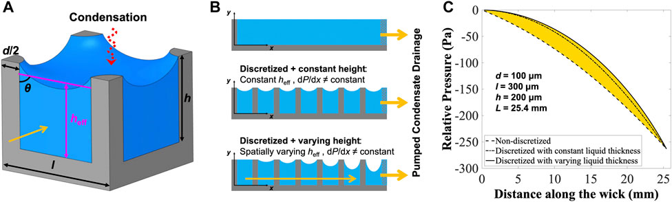
Figure 1. (A) The trimetric view of a discretized unit cell in a pillar array. (B) Schematic figure of the pillar arrays representing the non-discretized model and the discretized models with constant and varying liquid thickness (or pillar height). (C) Profiles of relative liquid (water) pressure along the pillar array wick calculated by the three different models with d = 100 μm, l = 300 μm, h = 200 µm and L = 25.4 mm. The predicted condensation heat flux is ≈ 105.5 W/cm2 for the data in (C) with spatially varying effective liquid height, and the working fluid is water at 30°C.
In the capillary-enhanced filmwise mode, the heat transfer coefficient (HTC) is defined as:
where, keff is the effective thermal conductivity of the porous media (i.e., pillar and condensate) (Li and Peterson, 2006; Gong et al., 2014), ks and kl are the solid and liquid/condensate thermal conductivity, respectively, and h is the pillar height. The surface subcooling (i.e., temperature difference between the vapor and the condenser surface) is calculated from an energy balance:
where, q" is the condensation heat flux, and hfg is latent heat of vaporization for water. The heat transfer coefficient (HTC) enhancement is defined as the ratio of the average capillary-enhanced HTC to the traditional filmwise condensation HTC: (Wang and Antao, 2018)
where, hcond-film or hNusselt, is calculated by integrating the local HTC along the condensate flow predicted by the Nusselt model for a thin falling film on a vertical flat substrate: (Nusselt, 1916)
where, ρv is the vapor density, and kl is the condensate thermal conductivity. Thermophysical properties for the different fluids studied here are obtained from the NIST REFPROP program (Lemmon et al., 2018).
Results and discussion
We first highlight the accuracy of the current model by comparing three different models to predict capillary-enhanced filmwise condensation performance: i) a non-discretized model assuming the porous media (i.e., condensate-pillar composite film) thickness is the pillar height and a uniform condensate flow velocity across the pillar array, ii) a discretized model with a uniform effective height, which is calculated by averaging the effective liquid heights in the first discretized cell (i.e., flat meniscus or pillar height) and the last discretized cell (i.e., the highest curvature meniscus obtained from the receding contact angle), and iii) the discretized model with spatially varying effective liquid height, where each discretized cell has its individual local meniscus shape, local contact angle and corresponding effective height which result in a spatially varying permeability. Schematic representations of the three models are shown in Figure 1B. In the literature, most analytical and semi-analytical models assume a constant effective permeability and thus a constant liquid height (Sangani and Acrivos, 1982; Ranjan et al., 2009; Srivastava et al., 2010; Xiao et al., 2010; Tamayol et al., 2012), which is similar to the first/second models discussed above. The average effective height from the first and the last cell in the second model is expected to give a more accurate prediction compared to using the pillar height, but the actual accuracy depends on the accuracy of the meniscus shape prediction (Alhosani and Zhang, 2017; Wang et al., 2019). Accounting for the spatially-varying meniscus shape is important because the liquid-vapor pressure difference increases in the direction of the condensate flow and hence leads to a larger meniscus curvature based on the Young–Laplace equation. Figure 1C compares the pressure profiles for a pillar array of length 25.4 mm (1 inch), and with pillar diameter, pitch and height of 100 μm, 300 μm and 200 μm, respectively, where water is the working fluid (T = 30°C). The near-linear pressure profile for the non-discretized model is calculated using the condensate velocity which is updated from the original linear pressure gradient assumption after one iteration. Both discretized models give accurate predictions that the pressure gradient is zero at the beginning of the pillar array and the highest pressure gradient exists near the end of the pillar array. A larger deviation between the two pressure profiles is expected for short pillars since the relative difference in the effective height at each location increases as the pillar height decreases due to the Γ bottom wall viscous effect factor in Eq. 2.
To emphasize the role and importance of the spatially varying effective height, we then maintain the same diameter, pitch and length of the pillar array (d = 100 μm, l = 300 μm, and L = 25.4 mm) and vary the pillar height in the model. Figure 2A presents the local HTC Enhancement along the pillar array in the flow direction for three different height ratios, short, medium and tall, which we define based on the pillar height ratio h/(l-d) = 1, 2, and 5 respectively, to demonstrate the difference between the two discretized models: constant condensate film thickness (dashed lines) and spatially-varying condensate film thickness (solid lines). The local HTC Enhancement predicted by the two models essentially overlap for tall pillars, which is expected because the variation in the two effective heights are negligible compared to the pillar height, or in other words, the effective heights themselves are close to the pillar height (i.e., a flat meniscus height). Nevertheless, as the pillar height ratio reduces, the difference between the two models increases and the model with constant condensate thickness leads to an over prediction in the local HTC Enhancement. Therefore, it is necessary to apply the locally varying effective liquid height to obtain an accurate prediction of the HTC Enhancement, especially for relatively short pillars. Furthermore, we demonstrate the difference between the varying height model and the constant height model by comparing the overall HTC Enhancement at different heights for d/l ratios of 1/3, 1/4 and 1/8 in Figure 2B. Similar to Figure 2A, the model with constant liquid height over predicts the HTC enhancement noticeably at lower height ratios, and this over prediction is higher for dense pillars (i.e., d/l = 1/3) due to the corresponding larger area ratio AR of the actual curved meniscus to the projected area. Additionally, dense pillar arrays exhibit higher HTC enhancement, because of the larger volume of high thermal conductivity material in the condensate and surface structure composite at any given length (i.e., more pillars for a dense array over a constant/fixed length of the pillar array wick), leading to a larger effective thermal conductivity and eventually the higher capillary-enhanced HTC (Eq. 4). Although increasing the d/l ratio of pillar arrays (i.e., denser pillar array) improves the HTC enhancement, Figure 2C shows that the condensation heat flux significantly decreases due to reduced condensation area (i.e., liquid-vapor interface) in denser arrays. Note, pillar diameter remains constant and pitch varies for different d/l ratios in Figure 2C, and the height ratio is kept constant at 1.
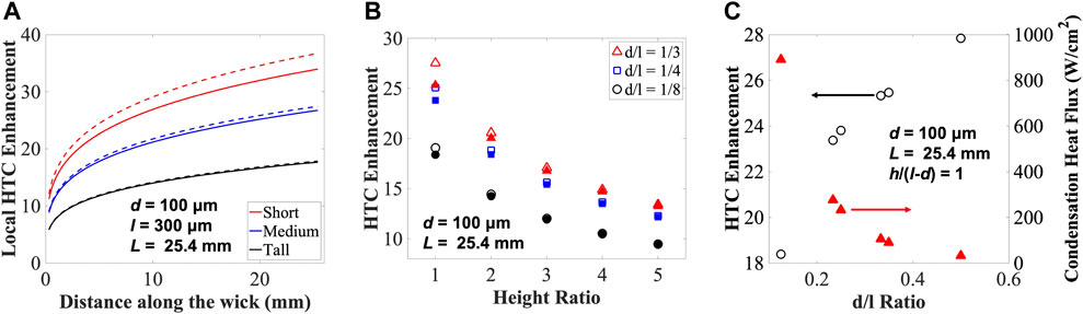
Figure 2. (A) Local HTC enhancement along the wick for geometries at different height ratios. Short, medium and tall pillars are defined based on the pillar height ratio h/(l–d) = 1, 2, and 5, respectively. Dashed lines represent the constant height discretized model, and solid lines represent the varying liquid height discretized model. (B) HTC enhancement for different d/l ratios at height ratios ranging from one to five. Open symbols represent the constant height discretized model, and filled symbols represent the varying liquid height discretized model. (C) HTC enhancement and condensation heat flux as functions of d/l ratio at a constant height ratio. The geometry is d = 100 μm and L = 25.4 mm. Water is the working fluid.
For the rest of this manuscript, we label/define the thickness or height of the pillar array porous media as wick thickness to demonstrate the scalability of the model. In order to present the limit of predicting the HTC Enhancement and maximum subcooling in a pillar array, we plot a regime map (Figure 3A) with the wick thickness and length as variables to display the maximum HTC Enhancement and maximum subcooling that can be achieved for specific geometries when using water as the working fluid. The colors represent the HTC Enhancement, the gray lines represent the maximum subcooling, and the condensate temperature is set to be 30°C in the model. Generally, larger enhancement is achieved at small thickness and short overall length due to the smaller thermal resistance and the lower effective HTC as predicted by the Nusselt model. Quantitatively, the HTC Enhancement predicted by the model can be determined by the pillar array dimensions (i.e., diameter, pitch, height, overall array length), the condensate temperature and the condensate properties, thus the degrees of freedom for modeling HTC Enhancement for a pillar array are 6. In an actual application scenario, some parameters such as overall array length, subcooling and working fluid, may be limited by the equipment size, cooling/heating power available or required, and the required working fluid and its chemical compatibility, in which case an optimal HTC Enhancement may be determined by tuning other parameters. For example, Figure 3B shows the maximum subcooling and the HTC enhancement as functions of wick thickness for a wick length of 100 mm. Increasing the wick thickness significantly raises the maximum subcooling (black line in Figure 3B), however, the average HTC Enhancement (red line in Figure 3B) decreases as the wick thickness increases due to the larger thermal resistance of a thicker wick-condensate composite layer (Eq. 4). Thus, a higher HTC Enhancement may be achieved by reducing the pillar height and sacrificing the maximum subcooling capability in the capillary-enhanced filmwise condensation mode without failure (i.e., flooding of the pillar array). This model is scalable and provides guidance for designing the optimal surface structure geometry for enhanced condenser applications.
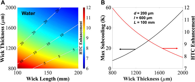
Figure 3. (A) Regime map for the HTC Enhancement of water. The color contours represent the HTC Enhancement and the gray contour lines represent the maximum subcooling before condensate flooding. (B) Maximum subcooling and HTC Enhancement as functions of the wick thickness for a wick length of 100 mm. The geometry of the pillar array is d = 200 μm, l = 600 μm, and the condensate temperature is 30°C.
Another advantage of the capillary-enhanced filmwise condensation mode is its compatibility with low surface tension liquids as it does not require any low surface energy coatings. We plot the regime maps (Figure 4) for common hydrocarbon and fluorocarbon fluid refrigerants such as propane, HFE7100, R-245fa and R-134a. The magnitude of the HTC enhancement (≈18–35 times compared to the traditional filmwise mode) for these refrigerants is noticeably higher than water (≈6–12 times), because the lower thermal conductivity and latent heat of vaporization for these non-polar (or dielectric) fluids lead to a lower hcond-film or hNusselt. The maximum subcooling of these low surface tension liquids are also lower than the maximum subcooling for water because of their significantly lower latent heat of vaporization, which directly affects the maximum subcooling (Eq. 5). Note that operating at a subcooling higher than the limit results in the failure of the capillary-enhanced filmwise mode, where the pillar array is flooded by a layer of the condensate. Although this maximum HTC Enhancement cannot be achieved after flooding, some enhancement (lower than the HTC Enhancement, Eq. 6) is possible, and this enhancement is dependent on the thickness of the flooding condensate film which acts as a thermal resistance in series with the pillar array wick. A solution to this more complex mode of operation may be obtained by combining the Nusselt model with our capillary-enhanced filmwise condensation model.
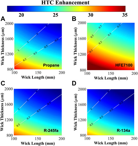
Figure 4. Regime maps predicting condensation HTC Enhancement with the pillar array for (A) propane, (B) HFE7100, (C) R-245fa, and (D) R-134a. The pillar dimensions are d = 200 μm, l = 600 μm, and the condensate temperature is 30°C.
Conclusions
To summarize, we report an integrated modeling framework to accurately predict the heat transfer characteristics during steady state condensation in the capillary-enhanced filmwise mode within a pillar array wick, where heat transfer enhancement is enabled by leveraging capillary pumping within the porous structure and the overall higher effective thermal conductivity of the condensate and porous media composite. The high accuracy of this model is facilitated by discretizing the modeling domain and capturing the spatially varying meniscus curvature and local effective liquid height. Additionally, this model predicts the operational limits (i.e., maximum subcooling and HTC ratio) corresponding to operational conditions (temperature, working fluid, etc.) for real-world condenser components. The advancements from this study provide guidelines to design and optimize the geometric properties of heat exchanger materials/surface structures for condensation heat transfer applications in thermal management and water-energy nexus systems by taking into account the effect that the liquid-vapor interface shape has on performance.
Data availability statement
The original contributions presented in the study are included in the article/supplementary material, further inquiries can be directed to the corresponding author.
Author contributions
RW and DSA conceived the study, RW performed the research, and RW and DSA wrote and edited the manuscript. All authors contributed to the article and approved the submitted version.
Funding
The authors acknowledge funding for this research from the J. Mike Walker ’66 Department of Mechanical Engineering at Texas A&M University.
Conflict of interest
The authors declare that the research was conducted in the absence of any commercial or financial relationships that could be construed as a potential conflict of interest.
Publisher’s note
All claims expressed in this article are solely those of the authors and do not necessarily represent those of their affiliated organizations, or those of the publisher, the editors and the reviewers. Any product that may be evaluated in this article, or claim that may be made by its manufacturer, is not guaranteed or endorsed by the publisher.
References
Adera, S., Alvarenga, J., Shneidman, A. V., Zhang, C. T., Davitt, A., and Aizenberg, J. (2020). Depletion of lubricant from nanostructured oil-infused surfaces by pendant condensate droplets. ACS Nano 14 (7), 8024–8035. doi:10.1021/acsnano.9b10184
Alhosani, M. H., and Zhang, T. (2017). Dynamics of microscale liquid propagation in micropillar arrays. Langmuir 33 (26), 6620–6629. doi:10.1021/acs.langmuir.7b01090
Anand, S., Paxson, A. T., Dhiman, R., Smith, J. D., and Varanasi, K. K. (2012). Enhanced condensation on lubricant-impregnated nanotextured surfaces. ACS Nano 6 (11), 10122–10129. doi:10.1021/nn303867y
Beér, J. M. (2007). High efficiency electric power generation: The environmental role. Prog. Energy Combust. Sci. 33 (2), 107–134. doi:10.1016/j.pecs.2006.08.002
Cavallini, A., Censi, G., Del Col, D., Doretti, L., Longo, G. A., Rossetto, L., et al. (2003). Condensation inside and outside smooth and enhanced tubes — A review of recent research. Int. J. Refrig. 26 (4), 373–392. doi:10.1016/s0140-7007(02)00150-0
Cha, H., Vahabi, H., Wu, A., Chavan, S., Kim, M. K., Sett, S., et al. (2020). Dropwise condensation on solid hydrophilic surfaces. Sci. Adv. 6 (2), eaax0746. doi:10.1126/sciadv.aax0746
Dalkilic, A. S., and Wongwises, S. (2009). Intensive literature review of condensation inside smooth and enhanced tubes. Int. J. Heat Mass Transf. 52 (15-16), 3409–3426. doi:10.1016/j.ijheatmasstransfer.2009.01.011
Das, A. K., Kilty, H. P., Marto, P. J., Andeen, G. B., and Kumar, A. (2000). The use of an organic self-assembled monolayer coating to promote dropwise condensation of steam on horizontal tubes. J. Heat Transf. 122 (2), 278–286. doi:10.1115/1.521465
Enright, R., Miljkovic, N., Alvarado, J. L., Kim, K. J., and Rose, J. W. (2014). Dropwise condensation on micro- and nanostructured surfaces. Nanoscale Microscale Thermophys. Eng. 18 (3), 223–250. doi:10.1080/15567265.2013.862889
Gong, L., Wang, Y., Cheng, X., Zhang, R., and Zhang, H. (2014). A novel effective medium theory for modelling the thermal conductivity of porous materials. Int. J. Heat Mass Transf. 68, 295–298. doi:10.1016/j.ijheatmasstransfer.2013.09.043
IEA (2015). Emissions reduction through upgrade of coal-fired power plants: Learning from Chinese experience. Paris: International Energy Agency.
Lee, S., Cheng, K., Palmre, V., Bhuiya, M. D., Kim, K. J., Zhang, B. J., et al. (2013). Heat transfer measurement during dropwise condensation using micro/nano-scale porous surface. Int. J. Heat Mass Transf. 65, 619–626. doi:10.1016/j.ijheatmasstransfer.2013.06.016
Lemmon, E. W., Bell, I. H., Huber, M. L., and McLinden, M. O. (2018). REFPROP- standard reference data program, 10.0. Gaithersburg, MD: National Institute of Standards and Technology NIST.
Li, C., and Peterson, G. P. (2006). The effective thermal conductivity of wire screen. Int. J. Heat Mass Transf. 49 (21-22), 4095–4105. doi:10.1016/j.ijheatmasstransfer.2006.03.031
Liu, Z., and Preston, D. J. (2019). Enhanced condensation for improved energy efficiency. Joule 3 (5), 1182–1184. doi:10.1016/j.joule.2019.04.008
Lu, Z., Preston, D. J., Antao, D. S., Zhu, Y., and Wang, E. N. (2017). Coexistence of pinning and moving on a contact line. Langmuir 33 (36), 8970–8975. doi:10.1021/acs.langmuir.7b02070
Nusselt, W. (1916). The surface condensation of water vapour. Z. Des. Vereines Dtsch. Ingenieure 60, 541–546.
Preston, D. J., Lu, Z., Song, Y., Zhao, Y., Wilke, K. L., Antao, D. S., et al. (2018). Heat transfer enhancement during water and hydrocarbon condensation on lubricant infused surfaces. Sci. Rep. 8 (1), 540. doi:10.1038/s41598-017-18955-x
Preston, D. J., Song, Y., Lu, Z., Antao, D. S., and Wang, E. N. (2017). Design of lubricant infused surfaces. ACS Appl. Mater Interfaces 9 (48), 42383–42392. doi:10.1021/acsami.7b14311
Preston, D. J., and Wang, E. N. (2018). Jumping droplets push the boundaries of condensation heat transfer. Joule 2 (2), 205–207. doi:10.1016/j.joule.2018.01.011
Preston, D. J., Wilke, K. L., Lu, Z., Cruz, S. S., Zhao, Y., Becerra, L. L., et al. (2018). Gravitationally driven wicking for enhanced condensation heat transfer. Langmuir 34 (15), 4658–4664. doi:10.1021/acs.langmuir.7b04203
Ranjan, R., Murthy, J. Y., and Garimella, S. V. (2009). Analysis of the wicking and thin-film evaporation characteristics of microstructures. J. Heat Transf. 131 (10). doi:10.1115/1.3160538
Renken, K. J., and Mueller, C. D. (1993). Measurements of enhanced film condensation utilizing a porous metallic coating. J. Thermophys. Heat Transf. 7 (1), 148–152. doi:10.2514/3.11582
Rose, J. W. (2002). Dropwise condensation theory and experiment: A review. Proc. Institution Mech. Eng. Part A J. Power Energy 216 (2), 115–128. doi:10.1243/09576500260049034
Sangani, A. S., and Acrivos, A. (1982). Slow flow past periodic arrays of cylinders with application to heat transfer. Int. J. Multiph. Flow 8 (3), 193–206. doi:10.1016/0301-9322(82)90029-5
Schilling, H. D. (1993). Improving the efficiency of pulverised coal fired power generating plant. VGB Kraftw. Engl. Ed.) 73 (8), 564–576.
Shekarriz, A., and Plumb, O. A. (1989). Enhancement of film condensation using porous fins. J. Thermophys. Heat Transf. 3 (3), 309–314. doi:10.2514/3.28777
Srivastava, N., Din, C., Judson, A., MacDonald, N. C., and Meinhart, C. D. (2010). A unified scaling model for flow through a lattice of microfabricated posts. Lab. Chip 10 (9), 1148–1152. doi:10.1039/b919942j
Tamayol, A., Khosla, A., Gray, B. L., and Bahrami, M. (2012). Creeping flow through ordered arrays of micro-cylinders embedded in a rectangular minichannel. Int. J. Heat Mass Transf. 55 (15-16), 3900–3908. doi:10.1016/j.ijheatmasstransfer.2012.03.008
Wang, R., and Antao, D. S. (2018). Capillary-enhanced filmwise condensation in porous media. Langmuir 34 (46), 13855–13863. doi:10.1021/acs.langmuir.8b02611
Wang, R., Jakhar, K., Ahmed, S., and Antao, D. S. (2021). Elucidating the mechanism of condensation-mediated degradation of organofunctional silane self-assembled monolayer coatings. ACS Appl. Mater Interfaces 13 (29), 34923–34934. doi:10.1021/acsami.1c08496
Wang, R., Guo, J., Muckleroy, E. A., and Antao, D. S. (2022). Robust silane self-assembled monolayer coatings on plasma-engineered copper surfaces promoting dropwise condensation. Int. J. Heat Mass Transf. 194, 123028. doi:10.1016/j.ijheatmasstransfer.2022.123028
Wang, R., Jakhar, K., and Antao, D. S. (2019). Unified modeling framework for thin-film evaporation from micropillar arrays capturing local interfacial effects. Langmuir 35 (40), 12927–12935. doi:10.1021/acs.langmuir.9b02048
Wilke, K. L., Antao, D. S., Cruz, S., Iwata, R., Zhao, Y., Leroy, A., et al. (2020). Polymer infused porous surfaces for robust, thermally conductive, self-healing coatings for dropwise condensation. ACS Nano 14 (11), 14878–14886. doi:10.1021/acsnano.0c03961
Wong, T. S., Kang, S. H., Tang, S. K., Smythe, E. J., Hatton, B. D., Grinthal, A., et al. (2011). Bioinspired self-repairing slippery surfaces with pressure-stable omniphobicity. Nature 477 (7365), 443–447. doi:10.1038/nature10447
Keywords: capillarity, enhanced condensation, robust condenser surfaces, low surface tension liquids, porous media condensation
Citation: Wang R and Antao DS (2023) Effect of meniscus curvature on phase-change performance during capillary-enhanced filmwise condensation in porous media. Front. Therm. Eng. 3:1131363. doi: 10.3389/fther.2023.1131363
Received: 24 December 2022; Accepted: 30 January 2023;
Published: 20 February 2023.
Edited by:
Abdolali K. Sadaghiani, Sabancı University, TürkiyeReviewed by:
Anton Valeev, Volgograd State Technical University, RussiaFeifei Qin, Northwestern Polytechnical University, China
Copyright © 2023 Wang and Antao. This is an open-access article distributed under the terms of the Creative Commons Attribution License (CC BY). The use, distribution or reproduction in other forums is permitted, provided the original author(s) and the copyright owner(s) are credited and that the original publication in this journal is cited, in accordance with accepted academic practice. No use, distribution or reproduction is permitted which does not comply with these terms.
*Correspondence: Dion S. Antao, ZGFudGFvQHRhbXUuZWR1