 Michael Huylo
 Kaiwu Huang2
 Roe-Hoan Yoon
 Rui Qiao
- 1Department of Mechanical Engineering, Virginia Tech, Blacksburg, VA, United States
- 2Department of Mining and Minerals Engineering, Virginia Tech, Blacksburg, VA, United States
Dewatering of fine coal is a significant industrial challenge with economic and environmental implications. Due to the lack of suitable dewatering technologies, fine coal particles are often discarded to waste impoundments, leading to substantial loss of valuable natural resources while creating environmental problems. The hydrophobic-hydrophilic separation (HHS) process is a unique solution to this problem. In this process, a recyclable solvent is used to simultaneously remove inorganic impurities (ash) and water from a run-of-mine fine coal slurry. A small amount of recyclable oil (or solvent) is added to a fine coal slurry so that the solvent can spontaneously displace the water from the surface of coal particles. The spent solvent is subsequently recovered and recycled in a closed loop. Here, we report the results obtained using two different solvents, i.e., pentane and hexane, to de-ash and dewater ultrafine coal and recover the spent solvent by filtration, followed by steam stripping. Most of the spent solvent can be recovered during the filtration step at 20 psig N₂ and at a 60 s filtration time. The residual solvent left in the cake was then recovered using steam under different conditions. The results showed that the residual solvent concentration could be reduced to <1,400 ppm after 10 s of steam stripping at 150°C and 15 psig.
1 Introduction
Dewatering of particulate materials is an essential operation in different industries ranging from mining to pharmaceutical manufacturing. Current dewatering techniques often suffer from high cost, low scalability, and low efficiency, particularly for finer particle sizes. Consequently, many industries are still significantly hindered by the lack of efficient fine particle dewatering technologies. For example, in the coal industry, where moisture is a critical inhibitor of product quality, particles less than 1 mm in size account for approximately 10% of the total product but can contain more than one-third of the total moisture (Osborne, 1988). Given the lack of suitable dewatering technologies, many coal operations in the U.S. discard all particles less than 44 µm to impoundments, causing significant losses in revenue and creating environmental liabilities. It is estimated that 70–90 million tons of fine coal waste are discarded annually and that more than 4 billion tons of waste are currently in impoundments throughout the US (Council, 2002; Kokkinos, 2018). Approximately one-third to one-half of the fine coal waste is recoverable coal, provided that efficient fine coal dewatering technologies become available.
Presently, there are two main strategies to dewater fine coal. One is to thermally evaporate water using fluidized bed dryers, multi-louvered systems, or flash-type systems (Jumah, 2006). These methods are expensive due to the high enthalpy costs and can produce fugitive dust and toxic elements that can escape into the environment. For these reasons, it has become difficult to obtain permits for thermal dryers in the U.S. (Gupta, 2014). The other strategy is to use mechanical means such as filtration or centrifugation to remove water. Fundamentally, mechanical dewatering becomes prohibitively inefficient with decreasing particle size. According to Poiseuille’s equation, which governs fluid flow through a filter cake, a ten-fold decrease in particle (or pore) size would require a 10⁴-times increase in pressure drop (ΔP) at a given filtration rate. In short, mechanical dewatering has reached its limit, which is partly the reason that the industry continues to discard coal fines to impoundments.
As an alternative approach, a co-author of this communication recently developed a novel fine coal cleaning and dewatering process known as hydrophobic-hydrophilic separation (HHS) (Gupta et al., 2016a; Gupta et al., 2016b; Yoon, 2016). This process has no lower particle size limit in solid-solid separation and produces practically dry coal as a final product. The HHS process has been successfully scaled-up from the bench to pilot scale and is subsequently at the commercial scale. At present, the first commercial plant is under shakedown testing.
In this process, a nonpolar solvent, typically a short-chain alkane (e.g., iso-hexane) with low enthalpy of vaporization and a low boiling point is introduced to an aqueous coal slurry. Because coal particles are hydrophobic, they spontaneously transfer from the water phase to the hydrophobic solvent phase. In principle, the transfer should entail spontaneous dewatering as water and oil do not mix. In the HHS process, a volume of oil (solvent) is introduced into an aqueous slurry of coal while being agitated to facilitate the transfer process. Under this condition, a small volume of water is entrained into the oil phase, resulting in the formation of a water-in-oil (w/o) emulsion.
Next, the water and hydrophobic solvents are phase-separated, and mechanical agitation is applied to mechanically destabilize the w/o emulsion, and thereby releasing the small droplets of water from the agglomerates. The water droplets liberated in this manner are then allowed to fall out of the oil phase into the aqueous phase below. In the final step, the low-boiling oil is recovered from the solvent-coal slurry and recycled back into the process in a closed loop. By removing and recovering all (>99.9%) of the solvent, the final product is effectively dry coal powder free of solvent, moisture, and other hydrophilic impurities. In practical operation, the moisture contents of the resulting coal particles are typically less than 4%–5% by weight regardless of particle size.
The solvent recovery step is a critical yet costly unit operation. Solvent lost to the coal product must be replenished in the process, thus increasing the operational cost. Given the cost and potential environmental concerns, extremely high solvent recoveries must be achieved. To achieve this outcome, a filtration step is used first (see Figure 1A). Here, mechanical filtration is first used to recover most of the free solvent. Slurry is inserted into a filtration chamber upstream of a filter cloth, then an inert gas is used to drive the solvent through the filter cloth, and as the gas displaces the solvent, a filter cake is formed. The filtration rate is determined by pressure drop, capillary pressure of solvents within the cake structure, and solvent viscosity (Huang et al., 2018). In past HHS experiments, N₂ has been used to drive the filtration (Yoon, 1995; Yoon, 2005). While filtration recovers most of the solvent, some residual solvents remain trapped in the filter cake, thus requiring further processing to reach the recovery levels needed for overall process viability.
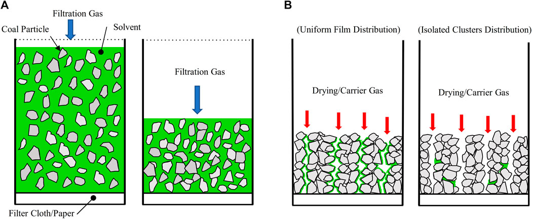
Figure 1. Two-step, in-situ recovery of nonpolar solvents from solvent-coal slurries. In Step I, an N₂ gas drives solvents through a filter paper/cloth, forming a filtration cake (A). In Step II, which starts after the gas breaks through the filtration cake, a drying/carrier gas is pumped through the cake to vaporize and remove the residual solvents (B). The schematics in (B) show two limiting scenarios that are possible for the distribution of residual liquid solvents (colored in green) at the beginning of Step II.
While supplemental thermal evaporation may be used to recover the residual solvent, we envision a streamlined solution, whereby the liquid-solid filtration step is integrated with a solvent vaporization and removal step in a single device. Following the first filtration step shown in Figure 1A, a second step, hereby denoted as the drying step, is introduced: a carrier gas is pumped through the filter cake to vaporize and remove the residual solvents (see Figure 1B). The envisaged scheme will allow significant equipment cost savings and easy integration into existing filtration systems. Potentially useful carrier gas includes nitrogen, heated nitrogen, and superheated steam. The speed and effectiveness of the solvent recovery in the second step depends critically on the distribution of liquid solvents inside the filtration cake. After gas breaks through the cake, the distribution of nonpolar liquids in a porous cake with micron-sized, complex-shaped particles is not well understood. There are two possible limiting scenarios (see Figure 1B). In the first scenario, the residual solvent forms a continuous film spanning across the surface of carrier gas pathways. In the second scenario, the residual solvent exists as isolated clusters that are sparsely dispersed in the filtration cake. Solvent recovery is expected to be facile in the first scenario but more difficult in the second.
Given this knowledge gap, the goal of this work is to experimentally investigate the envisioned in-situ solvent recovery scheme. The operation of this scheme involves many parameters such as filtration pressure, solid loading in slurry, and type, pressure, and temperature of the carrier gas. These parameters will be explored to determine solvent recovery efficacy and residual solvent concentrations. Based on preliminary technical assessments as well as general system constraints, the following process objectives were identified for the new solvent recovery scheme:
• Slurry filtration time <60 s,
• Solvent vaporization time <10 s,
• Final product solvent concentration <1,400 ppm.
These process objectives were required to allow for future pilot plant and commercial plant scale up, integration with available commercial manufacturing equipment, and ensuring economic viability of the process.
The remainder of this manuscript is organized as follows. Section 2 presents the experimental setup, materials, and methods for filtration experiments and solvent vaporization (drying) experiments. Section 3 presents the results from these experiments and insight into the optimization of in-situ solvent recovery scheme. The likely distribution of a solvent inside a filter cake will be deduced from the experimental data. Finally, conclusions are drawn in Section 4.
2 Materials, experiment setup, and methods
2.1 Materials
Before the filtration experiments, a coal-solvent slurry was prepared. For each test, a 25 g coal sample was weighed and mixed with the carrier solvent. Coal samples utilized in this study were originally recovered from the screen bowl effluent of a commercial coal preparation plant in Southern Appalachia. This material was then processed using a pilot-scale embodiment of the HHS process to obtain a clean coal product, which was then used as the feedstock for the laboratory-scale filtration and drying experiments of this study. The clean coal material had an 80% passing size (D₈₀) of 43.25 μm, and the overall particle size distribution is given in Table 1.
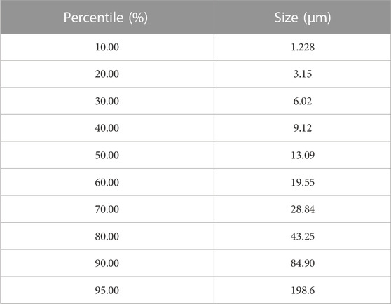
Table 1. Particle size distribution for the coal sample obtained from Warrior Met Coal Inc.
For the filtration tests, coal solvent slurries with solids concentrations of 10% and 15% (m/m) were used. Hexane was chosen as the primary solvent to be evaluated for this work, and pentane was also evaluated to serve as a comparator. Relevant properties for both solvents are shown in Table 2.
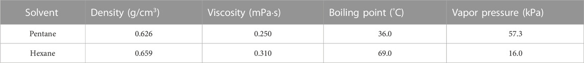
Table 2. Properties of solvents used in this work at 20°C and 1 atm.
2.2 Filtration tests
Initially, bench-scale filtration tests were performed to determine a reasonable filtration pressure. Pressure filtration was conducted using pressurized N₂, and the experiments were conducted using the experimental setup and measurement methods proposed by Huang et al. (Huang et al., 2018).
In each filtration run, a clean filter paper was installed into the bottom of a pressure cylinder above the fluid outlet. Next, a homogeneous solvent-coal slurry was poured into the pressure cylinder, and the cylinder top cap was sealed. Nitrogen delivery pressure was set, and the nitrogen valve was opened, injecting nitrogen into the filter to initiate the filtration test. Filtration continued until the gas broke through the filter cake. Tests were performed for pentane and hexane at 20, 40, 60 psig and 10% and 15% solids by weight.
2.3 Solvent vaporization and removal tests
As shown in Figure 1, the solvent trapped in micro-capillaries is difficult to remove by filtration. Instead, the residual solvent in the particle cake formed via filtration must be vaporized and then flushed out of the cake by a carrier gas. A key parameter of this process is the choice of carrier gas. For the current study, both nitrogen and superheated steam were evaluated. While nitrogen serves as a suitable control given its low cost and use in prior studies, superheated steam was also evaluated given its use in similar applications. Superheated steam-based drying is a well-studied, developed technology and is frequently utilized in drying food, grains, and minerals (Douglas, 1994; Johansson et al., 1997; van Deventer, 1997; Li et al., 1999; Pang and Dakin, 1999; van Deventer and Heijmans, 2001; Pronyk et al., 2004; Soponronnarit et al., 2006; Somjai et al., 2009; Speckhahn et al., 2010). Nevertheless, these applications have clear distinctions from the present work. Most use superheated steam to dry products containing water, but not organic solvent. Additionally, most works focused on drying using fluidized beds, jet impingement, rotary drums, or belt systems as opposed to a pressure cylinder (Douglas, 1994; Johansson et al., 1997; Li et al., 1999; van Deventer and Heijmans, 2001; Soponronnarit et al., 2006; Speckhahn et al., 2010; Jie Li and Bennamoun, 2016). The process studied here is unique in that vaporization is step two of a two-part solvent recovery method. Therefore, drying is conducted in the same vessel used for filtration in step one; superheated steam flows through the material to be dried (coal cake), and the drying product remains in contact with the pressure vessel enclosure.
Apparatus: the filtration apparatus utilized by Huang et al. (2018) was modified so that it can be used to perform both filtration and solvent vaporization and removal. A schematic layout of the final apparatus, capable of using ambient temperature nitrogen for filtration and heated nitrogen or steam for drying, is shown in Figure 2.
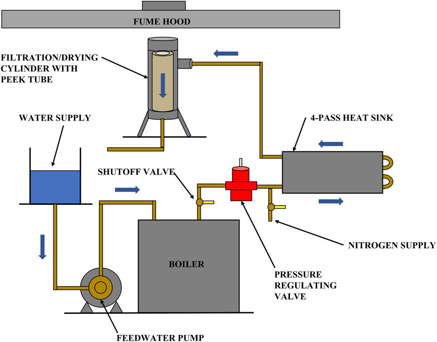
Figure 2. A schematic of the apparatus for combining filtration and solvent vaporization to recover organic solvents from coal slurries.
An electric steam boiler (MBA3100F3, Sussman) was used to provide steam. Downstream of the pressure regulating valve is a shutoff valve arrangement and a 4-pass high contact cold plate. The plate was preheated to the desired temperature and functioned as a heat sink during the drying experiment. The pressure cylinder in Figure 2 is internally insulated with an 8-in. high, 2.5-in. OD, 1.5-in. ID PEEK (Polyetheretherketone) plastic tube that effectively prevents steam condensation in the filtration cylinder. In addition to the above major components, nickel-plated brass-bodied check valves with stainless steel springs were installed to protect the nitrogen and steam reservoirs. Omega type-K plug thermocouples were used to monitor temperature at various points in the system. Steam and nitrogen pressures in the cylinder were measured with an Ashcroft commercial pressure gauge suitable for steam, rated for use up to 100 psig, and accurate to within ±3% of span.
Experimental protocol: before drying, filtration was completed by bypassing the filtration gas around any heated parts of the system. The filtration cake was left in the cylinder. To begin drying, all system temperatures were verified to be at the desired setting. Valves were then set to the desired flow setting, and the drying gas was injected into the cylinder until the desired time interval was reached. During the drying process, the gas temperature was monitored and recorded to ensure consistent results. At the end of the drying process, the drying gas supply valve was closed, and the coal cake was removed from the cylinder. Samples of the coal cake were collected and stored for chromatography testing.
Experiments performed: Table 3 summarizes the experimental parameters used in the drying tests. It is desirable to compare drying performance of nitrogen versus steam, while also identifying ideal temperature and pressure operating conditions. Pentane and hexane at room temperature are used to provide a baseline result before adding heating. Solvent vaporization testing was performed using filtration cakes from 10% by weight solvent-coal slurries.
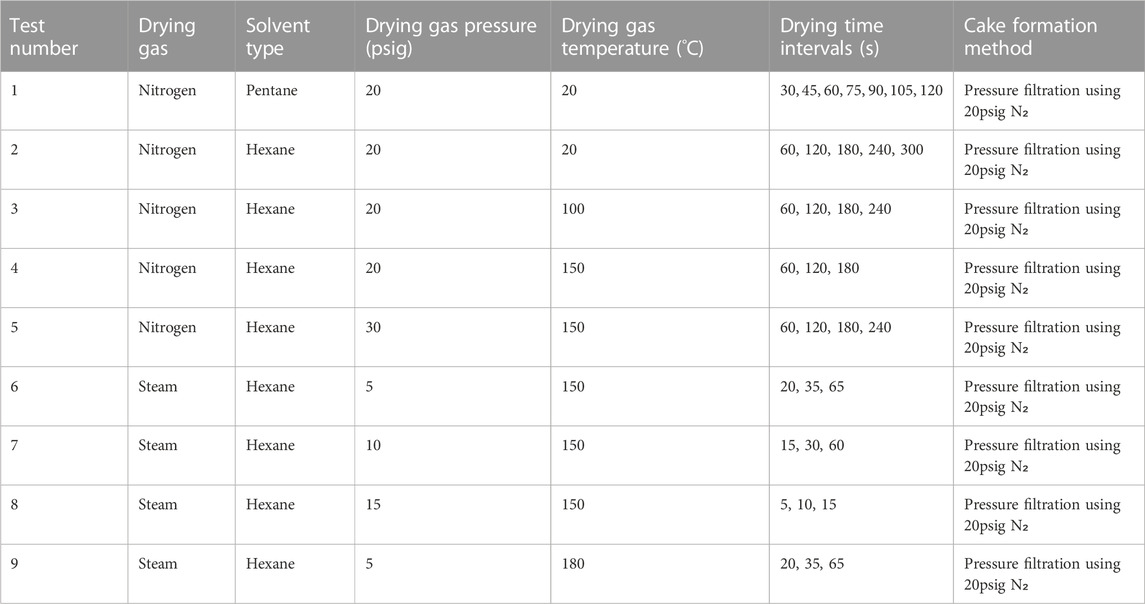
Table 3. Experimental parameters for the vaporization stage of the two-step solvent removal process.
2.4 Chromatography analysis
In this study, the amount of solvent in the filtration cake to be removed was typically less than a gram, while the residual solvent must be reduced to tens of milligrams. The experimental drying vessel, however, weighs more than 5 kg. As such, continuous monitoring of the solvent removal by gravimetric means (as is typical for filtration kinetic studies) was infeasible. As an alternative, kinetic data was instead collected by performing several independent experimental runs, each with different filtration and drying times. Samples of filtration cakes obtained at the end of these tests were analyzed using gas chromatography to determine the solvent concentration in them. This experimental approach reduced the time resolution of the drying curve; however, accurate drying data are available at pre-selected drying times, and the kinetic drying trends are still apparent.
3 Results and discussion
This section presents the results of in-situ solvent recovery that combines filtration and solvent vaporization. Results on liquid-solid separation through filtration are presented first, followed by solvent removal from the filtration cake through vaporization and convection by a carrier gas. Results are evaluated based on the process objectives for filtration time, drying time, and mass loading discussed in the introduction section.
3.1 Liquid-solid separation through pressure filtration
The first experiments conducted were filtration kinetics tests for hexane and pentane slurries of 10% and 15% solids by mass, filtered at 20, 40, and 60 psig. These tests provided the kinetic response for the filtration cycle and provided the data needed to select the optimal percent solid and filtration pressure to be used in the subsequent drying experiments. Figures 3A, B present the filtration curves for pentane-coal slurries with 10% and 15% solid mass loading, respectively.
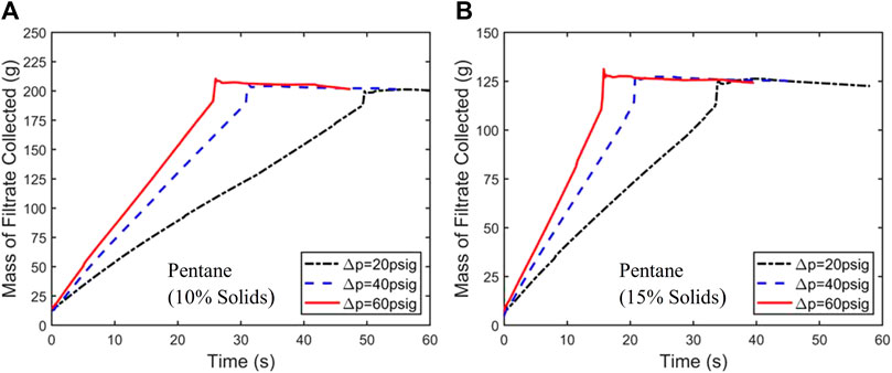
Figure 3. Mass of filtrate collected vs. time during filtration of pentane-coal slurries with a solid mass loading of 10% (A) and 15% (B) under a filtration pressure drop of 20, 40, and 60 psig. Similar experiments were also performed for hexane.
From the data shown in Figure 3, filtration times for different slurries and filtration pressure were obtained. The time at which the abrupt end of the jump in filtrate mass occurs is taken as the filtration time
Having completed filtration testing, it is useful to characterize the filtration cake, whose structure can greatly affect the subsequent drying step. To accomplish this, a model developed in Huang et al. (2018) was utilized to extract pore radius (R) and medium resistance (Rm) by fitting experimental filtration data displayed in Figure 3. The model equation is given in Eq. 1,
in which Q is volumetric flow rate, i.e., volume of solvent (V) removed per unit time (t), A cross sectional area of cake, ΔP pressure drop, μ viscosity of solvent, Xs solids concentration, ρs solid density, and k cake surface porosity.
Figure 4 shows the results of the curve fitting for the 10% solids in the 20 psig pentane filtration experiment, and quality of the fitting is good considering the complexity of the filtration process and the simplicity of the model. The curve fitting leads to a capillary radius of 1.28 µm in the filtration cake. This small radius is consistent with the small size of coal particles (see Table 1) and will be used later in this paper to provide more insight into the drying behavior of the fine coal particle cake.
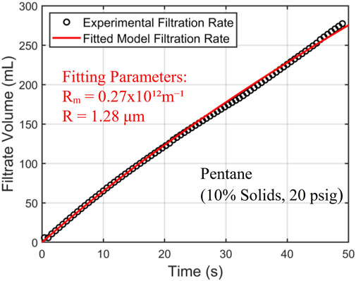
Figure 4. Experimental filtration results for the 10% solids pentane slurry at 20 psig (every third data point denoted by black circle) are fitted to the curve produced by the Huang et al. (2018) model (red curve). The fitting parameters (R) and (Rm) resulted in a capillary radius of 1.28 µm, and a medium resistance of 0.27 × 10¹²m−1.
Filtration experiments identified 10% solids 20 psig hexane as the ideal filtration method, and these parameters will be studied further for drying in section 3.2.
3.2 Drying through solvent vaporization and convection
In this section, we discuss the solvent removal during Step II of the in-situ solvent recovery process sketched in Figure 1. The solvent removal (or drying) here depends critically on the initial distribution of liquid solvents in the coal cake formed by pressure filtration, which is governed by the operating conditions of the pressure filtration step (Step I) of the in-situ solvent recovery process, e.g., filtration pressure and solid loading in coal slurries. All experiments presented below are preceded by the same pressure filtration step. Therefore, the distributions of liquid solvents in the filtration cake at the beginning of experiments below are comparable, regardless of whether N2 or superheated steam is used as the carrier gas.
3.2.1 Room-temperature N₂ drying
Drying tests were initially conducted with room-temperature nitrogen as the carrier gas to obtain a baseline drying performance. In addition to drying filtration cakes obtained by filtration of hexane-coal slurries, drying of filtration cakes with residual pentane was also tested to serve as a reference for comparison. Figure 5 presents the drying curves for filtration cakes with pentane and hexane as a function of time. The pressure difference driving the nitrogen flow through the cake is 20 psig.
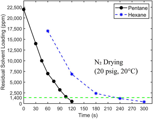
Figure 5. The drying curve of filtration cakes with pentane and hexane as residual solvents. 20 psig nitrogen at 20°C is used as the carrier gas. The target concentration of 1,400 ppm is denoted by a horizontal dashed line. The initial hexane loading is 24,500 ± 250 ppm.
Figure 5 shows that pentane is removed more quickly from filtration cakes than hexane. The residual pentane in filtration cakes reaches the target concentration of 1,400 ppm at ∼105 s, while it takes ∼230 s for hexane. To understand these results, we note that the drying of filtration cakes involves physical processes including phase change, heat transfer, and mass transfer by diffusion and convection. The last two processes greatly affect the drying rate, and they depend strongly on the distribution of liquid solvents in filtration cakes. The drying data in Figure 5, however, can help provide insights into the liquid distribution in filtration cakes. As mentioned earlier, there exists two limiting scenarios for the distribution of residual liquid solvent in a filtration cake. In the first scenario (see Figure 1A), at the end of the liquid-solid filtration step, liquid solvents form a continuous film transversing the filtration cake and are in close contact with the pathways of the carrier gas flow. In the second scenario (see Figure 1B), liquid solvents are trapped in tiny pores sparsely distributed in the filtration cake. Here, each major pathway of the carrier gas flow is in contact with a few liquid solvent clusters. While these different scenarios can potentially be clarified using numerical modeling (see, e.g., Wu et al., 2020) or advanced imaging, studying samples as large as the ones studied here while resolving liquid distribution in them at sub-micrometer scale is very challenging. Here, to examine which of these scenarios is closer to the actual scenario, we analyze the drying time based on the first scenario. Without losing generality, our analysis focuses on the drying of filtration cake with pentane as residual solvents.
Figure 6A shows a pore-scale model of the drying process based on the first scenario, where a representative pore inside the filtration cake is initially covered by a thin film of residual solvents. Since our measurements indicated that the temperature of a typical filtration cake decreases less than 6°C during the entire drying process, the drying is approximated as an isothermal process. Furthermore, the slow drying shown in Figure 5 is not limited by the kinetics of evaporation at liquid-vapor interfaces. Instead, drying is governed by the diffusion of solvent vapor from the evaporation site (pore walls) to the interior of the pore and the carrier gas flow along the pore. Because of the pore’s small radius R and its large length-to-radius ratio (L/R ∼ 10⁴), the gas flow in the pore is laminar and fully developed. Hence, the solvent removal rate from the pore can be estimated using the classical model for fully developed flows and mass convection in round pipes (Bejan, 2013).
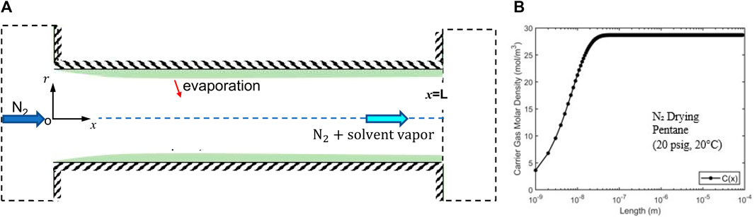
Figure 6. (A) A schematic of a pore-scale model for the drying (solvent vaporization and mass convection) of a filtration cake based on the assumption that the residual solvents form a continuous film on the pore walls. (B) Variation of the solvent vapor density along a representative pore (radius R = 1.28 µm; length L = 0.01 m).
Specifically, the average gas velocity in the pore is given by the Hagen-Poiseuille equation:
where ΔP is the pressure difference along the pore and μ is the viscosity of N₂. With the pressure difference (20 psig), pore length (0.01 m), and pore radius (1.28 µm) in our drying experiment,
where
Using the average velocity computed above, the vapor density along the pore is obtained (see Figure 6B). We observe that vapor density approaches the saturation density at a distance of L/104 from the pore’s entrance. This short distance is consistent with the small characteristic length for vapor density to reach saturation, i.e.,
Using the fact that the vapor density at the pore’s exit is
where
The drying time estimated above is almost 100 times smaller than that observed experimentally (120 s, see Figure 5). Such a dramatic discrepancy suggests that the assumption underlying the above estimation, i.e., the residual liquid solvents form continuous films lining the walls of the pathway of carrier gas flowing through the filtration cake, is inaccurate. Therefore, the second scenario for the distribution of residual solvent in the filtration cake is more likely, i.e., solvents exist as isolated liquid clusters sparsely distributed in filtration cakes, is more reasonable. The carrier gas is thus only in contact with “patches” of liquid solvents whose surface area is far smaller than the surface area in contact with the carrier gas flow. The remaining solvents are trapped in microcapillaries perpendicular to the main carrier gas pathway (see Figure 1B). Under this scenario, the carrier gas flow will not be saturated with solvent vapor when it leaves the filtration cake and thus the solvent removal is mainly limited by the transport of vaporized solvent from the evaporation site to the carrier gas flow pathway rather than by the convection of solvent vapor by the carrier gas flow.
The above analysis helps explain the drying curves in Figure 5. For example, the drying curves show that the drying rate decreases as solvents are removed from filtration cakes. Similar falling drying rate has been reported in many studies of the drying process in porous media, where the carrier gas usually flows over a porous media’s surface (Bond et al., 1994; Belhamri, 2003; Schlünder, 2004; Shibata, 2005). In those works, drying rate falls as the liquid saturation in a porous media becomes low. Under that condition, the capillary flow of water and diffusion of water vapor to the porous media’s surface becomes difficult, which slows down transport of water to the surface of porous media and hence the drying rate.
In the present study, although the carrier gas flows through filtration cakes, the distribution of the liquid solvent inferred from our above analysis is qualitatively similar to those revealed in previous drying studies. As such, similar falling drying rate can be expected. Figure 5 also shows that the drying of hexane is slower than pentane. This can be understood as follows. Here, the drying process is limited by the transport of solvent toward the pathway of the carrier gas flow. Because hexane has a lower vapor pressure and higher viscosity than pentane, the flux of hexane to carrier gas flow pathways (e.g., diffusion of hexane vapor from solvent patches and possibly capillary pumping of liquid hexane from the solvents that have receded into micro capillaries connecting to those pathways) tends to be smaller than that of pentane. Consequently, the drying of filtration cakes with hexane is slower than that of pentane-loaded filtration cakes.
Overall, Figure 5 shows that the hexane and pentane content in a filtration cake can be reduced to the target level (1,400 ppm) using room-temperature nitrogen flow. However, the cutoff drying times, defined as the time when the solvent content is reduced to the target level, are ∼10–20 times longer than the 10 s interval specified by the process objectives. To reduce the cutoff drying time, one possible strategy is to increase the temperature of the carrier gas flow. This will increase the vapor pressure of solvent and facilitates the transport of solvent vapor to the carrier gas pathway within filtration cakes, thereby accelerating drying.
3.2.2 Drying using heated N₂
Having shown that room-temperature nitrogen cannot dry filtration cakes to the desired level within the required time, we next use heated nitrogen with a pressure of 20 psig to dry cakes obtained from pressure filtration of hexane-coal slurries with 10% solid loading. Figure 7 displays the drying curves when the nitrogen temperature is 20°C, 100°C, and 150°C. The results in Figure 7 exhibit several interesting features. First, there was a significant reduction in drying time when N₂ temperature is increased from 20°C to 100°C. With 100°C N₂, the hexane concentration in filtration cakes reaches the target concentration at ∼150, 60–70 s shorter than when 20°C N₂ is used. Second, as N₂ temperature increases to 150°C, the improvement of drying performance is negligible. Finally, at elevated temperatures, the drying rate also decreases with time.
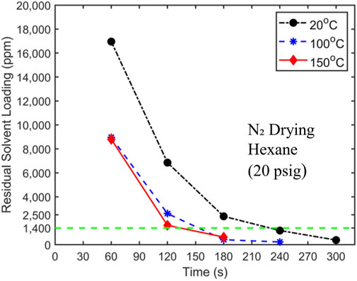
Figure 7. Hexane drying curves using 20 psig nitrogen at a temperature of 20°C, 100°C, and 150°C as the carrier gas. The target solvent concentration of 1,400 ppm is denoted by a dashed horizontal line. The initial hexane loading is 24,500 ± 250 ppm.
The reduction in drying time as N₂ temperature is increased from 20°C to 100°C is attributed to the fact that when the heated N₂ enters the filtration cake, it raises the temperature of the filtration cake and the liquid solvents in the cake. The latter increases the solvent vapor density in the cake, thereby facilitating more rapid solvent removal through mass convection. When the temperature of N₂ is elevated to 150°C, the cutoff drying time is shortened only marginally. It is interesting to note that hexane’s boiling points are 69.0°C and 98.6°C at 0 and 20 psig, respectively. It thus appears that raising the carrier gas temperature to 100°C likely causes rapid vaporization of liquid solvent that is absent when the temperature is 20°C. Further temperature rise above 100°C had less of an impact on the phase change of the liquid hexane. In the future, it would be interesting to perform experiments to examine how drying behavior varies as temperature increases from 69.0°C to 100°C.
It is notable that even when the carrier gas temperature is increased above hexane’s boiling point in the 150°C trial, drying time does not decrease significantly. This suggests that mass transfer from the evaporation site to carrier gas pathways remains a limiting factor in drying. The latter implies that violent phase change such as boiling, which should perturb coal particles in filtration cake to release trapped solvents and diminish the resistance for solvent transport to carrier gas flow through filtration cakes, does not occur at the temperature investigated here. The absence of boiling is likely caused by the fact that, for liquids trapped in sub-micrometer cavities, boiling is suppressed; instead, liquids become superheated, and phase change occurs only at their interfaces with solvent vapor or carrier gas.
3.2.3 Drying using superheated steam
Unable to produce satisfactory drying results using heated nitrogen, we conducted drying experiments using superheated steam as the drying medium and carrier gas. We report only experiments conducted with superheated steam at a temperature of 150°C because only they lead to potentially acceptable performance among the experiments performed. For example, steam with a temperature of 100°C resulted in coal products with high water content. Figure 8 displays the drying curves obtained using 150°C superheated steam with a pressure of 5, 10, and 15 psig at the entrance of the drying vessel. Two key observations are that 1) superheated steam offers a significant improvement of drying performance over the heated N₂ with the same temperature and 2) increasing steam pressure from 5 to 15 psig greatly enhances the drying performance.
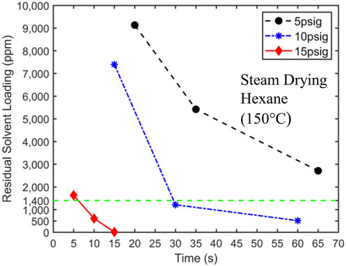
Figure 8. 150°C superheated steam drying curves at 5 psig, 10 psig, and 15 psig. The target solvent concentration of 1,400 ppm is denoted by a dashed horizontal line. The initial hexane loading is 24,500 ± 250 ppm.
Superheated steam offers much better drying performance over the heated N₂ with the same temperature. For 10 psig superheated steam, the target solvent concentration is reached at approximately 30 s. This drying result is in contrast to the fact that N₂ flow driven by twice the pressure difference (20 psig) did not reach the target concentration until approximately 130 s (see Figure 7). Furthermore, by reducing the solvent concentration to below 1,400 ppm within approximately 6 s, the 15 psig superheated steam meets the process objectives. It should be possible to optimize the steam pressure further so that the target solvent concentration is reached at 10 s. However, this optimization is not pursued here since 15 psig steam provides a reasonable safety margin for drying time, which will be helpful in practical scale-up.
The much better drying performance of superheated steam over N₂ of the same temperature is attributed to the different drying mechanisms of these two carrier gases. Unlike N₂, when steam enters the filtration cakes at room temperature, it condenses rapidly. The heat thus released is significantly greater than that afforded by heated N₂. For example, when steams with a temperature of 150°C at 5, 10, and 15 psig condense into saturated liquids at the same pressure, their specific enthalpies decrease by 2,320.8, 2,289.1, and 2,261.9 kJ/kg, respectively. On the other hand, even if N₂ with a temperature of 150°C is cooled to 20°C, its specific enthalpy decreases only by about 136.5 kJ/kg. As such, solvents are vaporized at a higher rate when steam is used, which facilitates solvent removal from filtration cakes and results in faster drying. Conceivably, the condensation of water in the filtration cake can block some pores in the cake, trap liquid solvents, and slow down drying. However, the superior drying performance shown in Figure 8 suggests that these processes are not very significant.
For superheated steam, the drying rate increases significantly as its pressure increases from 5 to 15 psig. This can likely be attributed to the increased steam flow into the filtration cake as steam pressure increases, whose condensation facilitates the vaporization of solvents in the cake.
During the early stage of drying, the steam condenses on the inner surface of filtration cakes. Driven by the heat transfer from the superheated steam, the liquid condensates are later vaporized and removed from the filtration cake by convection. Because the ultimate goal of HHS technology and the present work is coal dewatering, it is necessary to determine the residual water content in the filtration cake at the end of drying. Tests were conducted on all three cake samples, and the water content was all below 5%. In the industrial handling of coal, the moisture content of coal is an important parameter to monitor because if coal becomes too dry, it can be a safety hazard. If it is too wet, the heating value is reduced and can cause problems during transportation. Typical market specifications require coal moisture to be below 8% (Gupta, 2014). Therefore, the water content in coal dried here is acceptable. Further study of controlling moisture content by varying superheated steam temperatures and pressures can be conducted if more precise moisture control is required.
4 Conclusion
The hydrophobic-hydrophilic separation (HHS) process is a novel approach to fine particle separation that has been shown to clean and dewater fine coals with no lower particle size limit. In an intermediate step, the HHS process produces fine coal dispersed in hydrophobic solvents. This solvent is then recovered and recycled, creating a closed-loop process that is economically and environmentally beneficial. In this work, an in-situ solvent recovery scheme is used to achieve this goal by reducing the solvent content of the final product to less than 1,400 ppm. This scheme includes a liquid-solid filtration stage to recover most of the solvents and a drying stage to reduce the solvent concentration to the target concentration. The drying stage immediately follows the filtration stage and involves vaporizing solvents in the filtration cake and the subsequent removal through convection by a carrier gas. A series of experiments were carried out to identify filtration and drying operations that reduce the solvent concentration to the target concentration within specified filtration time and drying time objectives of 60 and 10 s, respectively.
Our experiments showed that pressure filtration with 20 psig nitrogen could not produce the desired target concentration within the 60-s filtration time constraint. Analysis aided by the classical model of mass convection in round pipes revealed that the residual solvents at the end of filtration exist in the form of isolated clusters trapped in small cavities that are sparsely distributed in the filtration cake. Given the critical importance of the initial distribution of liquids in filtration cake in the drying performance, it is highly desirable to measure such distribution directly. In particular, in-situ and non-intrusive measurements of liquid mass with characteristic dimensions of micrometers will provide valuable insights into the drying of the coal filtration cakes studied here.
Our experiments revealed that room-temperature N2 or N2 heated to 150°C, even at an elevated pressure of 30 psig, could not reduce the solvent concentration in filtration cakes to the target concentration within 10 s. We found, however, that drying using 15 psig steam superheated to 150°C can reduce solvent concentration below 1,400 ppm in less than 10 s, and the water content in the final filtration cakes does not exceed the limit set for commercial clean coal. These data provide the foundation for future scale-up studies of the in-situ solvent recovery process examined in this work.
Data availability statement
The original contributions presented in the study are included in the article/Supplementary Material, further inquiries can be directed to the corresponding authors.
Author contributions
Author MH designed and performed experiments, analyzed data, and prepared the initial draft of the manuscript. Author KH assisted initial experimental setup, guided the experimental design, and data analysis. Authors AN, R-HY, and RQ collaboratively idealized and formulated the problem. All authors contributed to the article and approved the submitted version.
Funding
The support of the United States Department of Energy, National Energy Technology Laboratory through NETL-Penn State University Coalition for Fossil Energy Research (UCFER, contract number DE-FE0026825) is gratefully acknowledged.
Acknowledgments
We thank the University Library at Virginia Tech for publication support through the open-access subvention fund.
Conflict of interest
The authors declare that the research was conducted in the absence of any commercial or financial relationships that could be construed as a potential conflict of interest.
Publisher’s note
All claims expressed in this article are solely those of the authors and do not necessarily represent those of their affiliated organizations, or those of the publisher, the editors and the reviewers. Any product that may be evaluated in this article, or claim that may be made by its manufacturer, is not guaranteed or endorsed by the publisher.
References
Belhamri, A. (2003). Characterization of the first falling rate period during drying of a porous material. Dry. Technol. 21 (7), 1235–1252. doi:10.1081/DRT-120023178
Bond, J. F., Mujumdar, A. S., van Heiningen, A. R. P., and Douglas, W. J. M. (1994). Drying paper by impinging jets of superheated steam. Part 1 Constant drying rate in superheated steam. Can. J. Chem. Eng. 72 (3), 446–451. doi:10.1002/cjce.5450720309
Council, N. R. (2002). Coal waste impoundments: risks, responses, and alternatives. Washington, DC, United States The National Academies Press.
Douglas, W. J. M. (1994). Drying paper in superheated steam. Dry. Technol. 12 (6), 1341–1355. doi:10.1080/07373939408961009
Gupta, N. (2014), Development of a novel fine coal cleaning and dewatering technology, Doctor of Philosophy. Blacksburg, VA, United States Virginia Polytechnic Institute and State University.
Gupta, N., li, B., Luttrell, G., Yoon, R. H., Bratton, R., and Reyher, J. “Hydrophobic-hydrophilic separation (HHS) process for the recovery and dewatering of ultrafine coal,” in Proceedings of the 2016 SME Annual Meeting, Phoenix, AZ, United States, February 2016a.
Gupta, N., Yoon, R. H., li, B., Luttrell, G., Bratton, R., Reyher, J., et al. “HHS process: a new approach for recovering fine Illinois basin coals,” in Proceedings of the International Coal Prep 2016, Louisville, KY, United States, April 2016b.
Huang, K., Pan, L., and Yoon, R. H. (2018). A capillary flow model for filtration. Miner. Eng. 115, 88–96. doi:10.1016/j.mineng.2017.10.012
Jie Li, Q.-C. L., Bennamoun, L., and Bennamoun, L. (2016). Superheated steam drying: design aspects, energetic performances, and mathematical modeling. Renew. Sustain. Energy Rev. 60, 1562–1583. doi:10.1016/j.rser.2016.03.033
Johansson, A., Fyhr, C., and Rasmuson, A. (1997). High temperature convective drying of wood chips with air and superheated steam. Int. J. Heat Mass Transf. 40 (12), 2843–2858. doi:10.1016/S0017-9310(96)00341-9
Jumah, R. Y. (2006). “Dryer emission control system,” in Handbook of industrial drying. Editor A. S. Mujumdar (Boca Raton, FL, USA CRC Press), 1058.
Kokkinos, A. (2018). Improving competitiveness of U.S. Coal dialogue. Washington, D.C., United States U.S. Department of Energy DOE.
Li, Y. B., Seyed-Yagoobi, J., Moreira, R. G., and Yamsaengsung, R. (1999). Superheated steam impingement drying of tortilla chips. Dry. Technol. 17 (1-2), 191–213. doi:10.1080/07373939908917525
Pang, S., and Dakin, M. (1999). Drying rate and temperature profile for superheated steam vacuum drying and moist AIr drying of softwood lumber. Dry. Technol. 17 (6), 1135–1147. doi:10.1080/07373939908917599
Pronyk, C., Cenkowski, S., and Muir, W. E. (2004). Drying foodstuffs with superheated steam. Dry. Technol. 22 (5), 899–916. doi:10.1081/DRT-120038571
Schlünder, E. U. (2004). Drying of porous material during the constant and the falling rate period: a critical review of existing hypotheses. Dry. Technol. 22 (6), 1517–1532. doi:10.1081/DRT-120038738
Shibata, H. (2005). Comparison of drying rate curves of porous solids in superheated steam to those in air. Dry. Technol. 23 (7), 1419–1434. doi:10.1081/DRT-200063499
Somjai, T., Achariyaviriya, S., Achariyaviriya, A., and Namsanguan, K. (2009). Strategy for longan drying in two-stage superheated steam and hot air. J. Food Eng. 95 (2), 313–321. doi:10.1016/j.jfoodeng.2009.05.005
Soponronnarit, S., Prachayawarakorn, S., Rordprapat, W., Nathakaranakule, A., and Tia, W. (2006). A superheated-steam fluidized-bed dryer for parboiled rice: testing of a pilot-scale and mathematical model development. Dry. Technol. 24 (11), 1457–1467. doi:10.1080/07373930600952800
Speckhahn, A., Srzednicki, G., and Desai, D. K. (2010). Drying of beef in superheated steam. Dry. Technol. 28 (9), 1072–1082. doi:10.1080/07373937.2010.505547
van Deventer, H. C. (1997). Feasibility of energy efficient steam drying of paper and textile including process integration. Appl. Therm. Eng. 17 (8), 1035–1041. doi:10.1016/S1359-4311(97)00042-2
van Deventer, H. C., and Heijmans, R. M. H. (2001). Drying with superheated steam. Dry. Technol. 19 (8), 2033–2045. doi:10.1081/DRT-100107287
Wu, H., Fang, C., Wu, R., and Qiao, R. (2020). Drying of porous media by concurrent drainage and evaporation: a pore network modeling study. Int. J. Heat Mass Transf. 152, 118718. doi:10.1016/j.ijheatmasstransfer.2019.118718
Yoon, R.-H. (2016). “Method for separating and de-watering fine particles,”. US patent US009518241B2.
Keywords: coal fines, dewatering, steam stripping, filtration cakes, drying
Citation: Huylo M, Huang K, Noble A, Yoon R-H and Qiao R (2023) Solvent recovery from solvent-fine coal slurries by filtration and steam stripping. Front. Therm. Eng. 3:1239800. doi: 10.3389/fther.2023.1239800
Received: 14 June 2023; Accepted: 07 August 2023;
Published: 22 August 2023.
Edited by:
Feifei Qin, Northwestern Polytechnical University, ChinaCopyright © 2023 Huylo, Huang, Noble, Yoon and Qiao. This is an open-access article distributed under the terms of the Creative Commons Attribution License (CC BY). The use, distribution or reproduction in other forums is permitted, provided the original author(s) and the copyright owner(s) are credited and that the original publication in this journal is cited, in accordance with accepted academic practice. No use, distribution or reproduction is permitted which does not comply with these terms.
*Correspondence: Roe-Hoan Yoon, cnlvb25AdnQuZWR1; Rui Qiao, cnVpcWlhb0B2dC5lZHU=