 Yuhao Wan
 Xiaoyan Zhao
 Guangze Zhang2
 Bernd Wünnemann
- 1Faculty of Geosciences and Environmental Engineering, Southwest Jiaotong University, Chengdu, China
- 2China Railway Eryuan Engineering Group Co., Ltd., Chengdu, China
- 3Institute of Geographical Sciences, Freie Universität Berlin, Berlin, Germany
Phyllite bimrocks are widely distributed in the eastern margin of the Tibetan Plateau, and it is the main geomaterial for landslides, slopes, dam basement and subgrades in this area. However, the flow behavior of phyllite bimrocks is unknown, especially the flow behavior of phyllite bimrocks with the orientation of blocks. This paper reports the coupling characteristics of flow and orientation of blocks in phyllite bimrocks. The flow behavior of phyllite bimrocks with different block percentages and block sizes was studied by a series of permeability experiments. A large-scale permeability apparatus was designed, and specimens with varying percentages of block and block sizes were produced by the same dip angle of blocks and compaction degree. Based on the Reynolds number analysis, it was found that the flow in phyllite bimrocks becomes laminar to turbulent under lower hydraulic gradient, and the flow behavior of phyllite bimrocks does not obey Darcy’s law. Furthermore, the Forchheimer equation is better at analyzing the flow behavior of phyllite bimrocks compared with Izbash equation. In addition, based on the coefficients a in the Forchheimer equation, the hydraulic conductivity of phyllite bimrocks can be calculated. The calculation result shows that when the percentage of blocks is 25%, the hydraulic conductivity reaches the minimum. Besides, the hydraulic conductivity increases approximately linear with the block size increase. On the basis of previous studies, coefficients A and B of the Forchheimer equation are detected by the normalized objective function analysis. The results would provide a valuable reference for risk assessment and prevention of phyllite bimrock slope.
Introduction
During the weathering process of rock, rock blocks and soil are generated, which accumulate at the toe of the hillslopes and form the bimrocks. Bimrocks are inhomogeneous and loose geomaterial, consisting of a certain percentage of rock blocks and soils (Kalender et al., 2014; Medley and Goodman, 1994; Medley and Lindquist, 1995; Xu et al., 2011). In the eastern margin of the Tibetan Plateau, a large number of phyllites called the Maoxian Group of Silurian are widely distributed (Figure 1A; Tan and Li, 1959; Tong, 1984). In such metamorphic rocks, a well-developed flaky structure can be observed. This structure makes the mechanical properties different from other rocks (Xu et al., 2018; Liu et al., 2020). In this area, the phyllite bimrocks (Figure 1B) composed of phyllite blocks and phyllite soil are also widely distributed, resulting in a large number of geological hazards. Along the phyllite hillslope, the phyllite blocks and phyllite soil will accumulate and generate the phyllite bimrocks at the toes of the phyllite hillslope. The phyllite blocks produce a similar imbricate texture in the phyllite bimrocks due to the flat shape of the phyllite blocks (Figure 1C). The similar imbricate texture in the phyllite bimrocks is defined as the orientation of blocks in this paper. During the rainy season, landslides and debris flow frequently occur in the Maoxian Group area (Song et al., 2020; Chen and Song, 2021). Besides, many previous studies are only concerned with studying the mechanical properties of bimrocks (Lin et al., 2019; Du et al., 2020; Song et al., 2021; Yu, 2021). Consequently, the flow behavior of phyllite bimrocks plays a critical role in studying the physical and mechanical properties of geological bodies in this area and has increasingly attracted the attention of many scholars and engineers (Wan et al., 2022).
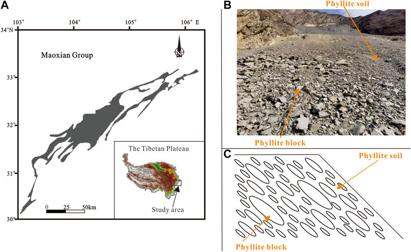
FIGURE 1. Phyllite bimrocks distribution and orientation of blocks in phyllite bimrocks. (A) The distribution of phyllite (Maoxian Group, Silurian) at the eastern margin of the Tibetan Plateau; (B) Structure of phyllite bimrocks, which is composed of phyllite blocks and phyllite soil; (C) Schematic diagram of the orientation of blocks in phyllite bimrocks (the phyllite blocks generate a similar imbricate texture in phyllite bimrocks).
Medley (1994) first proposed the definition of bimrock, a mixture of rocks composed of geotechnically significant blocks within a bonded matrix of finer texture. The bimrocks are also called block-in-matrix rocks or soil-rock mixtures. The permeable properties of this geomaterial were widely studied by many scholars. Dunn and Mehuys (1984) measured the saturated hydraulic conductivity of bimrocks by the constant-head method. The saturated hydraulic conductivity is in negative proportion to the rock volume fraction. Shakoor and Cook (1990) reported that the hydraulic conductivity of bimrocks did not show much variation within the rock percentage of 0%–50% but increased four to five orders of magnitude between 50% and 70%. Indrawan et al. (2006) studied the effects of sand with different percentages and sizes on the permeability property of soil-sand mixture. They found that when the sand percentage is over 50% in the soil, the permeability coefficient of the soil-sand mixture increases with the sand size, but less than 50% is the opposite. Zhou et al. (2006) investigated the effect of rock percentage, shape and porosity on the hydraulic conductivity of bimrocks by using the constant head permeameter. Besides, based on the orthogonal test, the influencing order was presented. Shafiee (2008) studied the effects of rock percentage, rock size and confining stress on the permeability of clay. The results showed that the permeability might vary with the increased content of the granule. However, when granule size or confining stress increases, the permeability decrease, and the permeability has an apparent relationship with the plasticity of the clay. Xu and Wang (2010) developed software to study the flow behavior of bimrocks with various rock block percentages, sizes, and spatial distributions based on the Darcy flow. Xiang and Jiang (2011) used the numerical simulation method (PFC) to investigate the permeability characteristics of the bimrocks. They reported that Darcy’s law could be applied to analyze the flow behavior of bimrocks at low seepage velocity. Gutierrez and Vallejo (2013) studied the effects of the percentage and size of the rock blocks on the hydraulic conductivity of bimrocks. They found that the hydraulic conductivity negatively correlates with the blocks percentage and size. Chen et al. (2014) carried out field experiments to investigate the effect of coarse grain percentage on bimrocks. The experiment results showed that when the coarse grain percentage is between 60% and 70%, the permeability coefficient increases sharply with the increase of coarse grain percentage. Moreover, the flow behavior obeys Darcy’s law. Wang et al. (2016a) studied the flow characteristics of bimrocks. They found that the flow behavior of bimrocks complies with the Izbash equation, and the average hydraulic conductivity of bimrocks gets the minimum at the rock black percentage is 40%. Wang et al. (2016b) also investigated the permeability characteristics of bimrocks under confining compression. The result showed that the hydraulic conductivity of bimrocks is negatively correlated with axial stress. Besides, the relationship between hydraulic conductivity and axial stress offers various with different rock block percentages. Zhou et al. (2017) used the constant head permeability experiment to study the seepage characteristics of bimrocks, and presented a theoretical model for the hydraulic conductivity of bimrocks. Wang et al. (2021) used the constant head permeameter to investigate the permeability and seepage characteristics of bimrocks. The results showed that the order of factors on permeability is rock content>cementation degree>rock size>Talbot index, and permeability of bimrocks increases with the increase of rock content and decreases with the increase of clay content.
From the above research, the coupling characteristics of flow and orientation of blocks are still unclear. Almost all the literature studied the effects of block percentage and size on the hydraulic conductivity of bimrocks by using constant head permeability tests. They assumed that the flow behavior of bimrocks complied with Darcy’s law and concluded that hydraulic conductivity is a constant value. However, whether Darcy’s law applies to phyllite bimrocks remains unclear. Some researchers claimed that the flow of some porous media deviates from Darcy conditions and enters into a new phase known as non-Darcy conditions (Soni et al., 1979; Sidiropoulo et al., 2007). Thus, in this study, to unravel the flow behavior of phyllite bimrocks with the orientation of blocks, a large-scale variable head permeability apparatus was designed and obtained the relationship between hydraulic gradient, Reynolds number and flow velocity. In addition, the hydraulic conductivity of phyllite bimrocks with different block percentages and block sizes under the orientation of blocks was discussed. Furthermore, the flow law of phyllite bimrocks was established in this paper.
Experimental Methods
To quantitatively describe the orientation of blocks, the orientation angle (α) is defined in this paper. The orientation angle (α) is defined as the dip angle of the phyllite blocks (Figure 2) and is close to the hillslope dip angle.
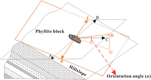
FIGURE 2. Schematic diagram of the orientation angle (α). OE and OF are the strike direction of the phyllite block; OA and OB are the strike direction of the bimslope; OD is the dip direction of the phyllite block; OC is the dip direction of the bimslope; OG is the projection of OD on the phyllite bimrock surface plane; orientation angle (α) is the angle between the OD and OG.
Experimental System
In the permeability test, the effect of wall effects on the flow behavior of specimens must be considered. In general, the larger the ratio of the diameter of the packed column to the particle size, the smaller the wall effect. Hansen (1992) reported that wall effects could be excluded when the ratio of the diameter of the packed column to the average particle size of grains is larger than 10. However, most permeability testing apparatuses are not suitable for exploring the permeability of phyllite bimrocks because the size of phyllite blocks is large. Therefore, a self-developed large-scale permeability apparatus was designed to test the permeability property of phyllite bimrocks (Figure 3). According to the Code for Coarse-Grained Soil Tests for Hydropower and Water Conservancy Engineering (DL/T5356-2006DL/T5356-2006), the sample height should not be less than the sample diameter. Thus, the diameter (d) and the height (L) of the sample were selected as 40 and 40 cm, respectively.
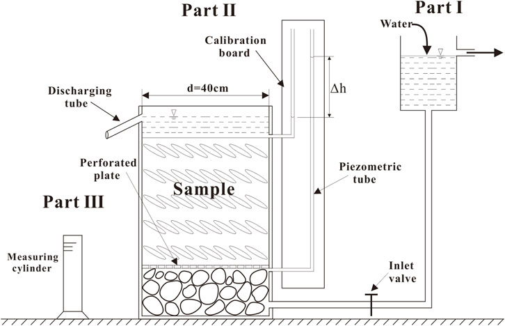
FIGURE 3. Schematic diagram of large-scale permeability apparatus.
The experimental apparatus for the permeability test of phyllite bimrocks consists of the water supply part (Part I), water head measurement part (Part II) and discharge collection part (Part III). The overall setup is shown in Figure 3.
The water supply part comprises an inflow and overflow pipe, water tank and height adjustment device. The water flows into the water tank through the inflow pipe. Once the water level reaches a certain height, it flows out through the overflow pipe. By adjusting the height of the water tank, the water can inject at various rates or pressure into the sample. Therefore, different seepage velocities and hydraulic gradients can be set up.
The water head measurement part consists of an acrylic cylinder, cobblestone, acrylic perforated plate, discharge tube, calibration board, inlet valve, and piezometric tube. The water enters the water head measurement system from the bottom of the acrylic cylinder. The cobblestones are filled in the bottom of the cylinder, allowing water to spread from the entry point. The acrylic perforated plate can hold the sample and enable the water to flow into the sample. After the water flow through the sample, the water head difference
The discharge collection part is made up of a measuring cylinder. The seepage water flows out through the discharge tube and is collected by the measuring cylinder. Accordingly, the seepage water volume
Experimental Materials
In the experimental test, the threshold grain size of phyllite soil and phyllite rocks in phyllite bimrocks must be confirmed. Xu and Hu (2006) called it the soil/rock threshold. Additionally, according to the research by Medley (1994) and Xu and Hu (2006), the soil/rock threshold could be defined as:
where
where A is the area of cross-section of specimen.
The calculation result shows the
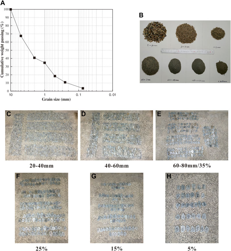
FIGURE 4. Experimental materials. (A) Grain size distribution of the phyllite soil; (B) Raw sand matrix materials; (C–E) Phyllite block sizes of 20–40, 40–60 and 60–80 mm, respectively; (E–H) Phyllite block percentages of 35%, 25%, 15%, and 5%, respectively.
Some fine phyllite particles less than 10 mm also have the orientation of blocks in phyllite bimrocks. However, it is hard to reproduce the orientation of blocks manually due to the small particle size and colossal quantity. Besides, assuming these fine phyllite particles are used as the matrix without considering the orientation of blocks, it may affect the accuracy of the permeability test of the phyllite bimrocks. Furthermore, the orientation of blocks is the focus of this study, and the irrelevant influence factors should be excluded as much as possible. Thus, the sand is selected as the matrix because it has no orientation of blocks. Accordingly, the sand replaces the phyllite soil with the same grain size distribution (Figure 4B). According to DL/T5356-2006, the ratio between the diameter of the sample and the maximum particle size should be greater than 5. Therefore, the maximum size of phyllite blocks is 80 mm, and phyllite block sizes of 20–40, 40–60, and 60–80 mm are adopted in the test (Figures 4C–E).
After several attempts, the result indicates that the maximum value of phyllite block percentage is 35% by mass. When the phyllite block percentage is larger than 35%, the phyllite blocks not be surrounded by the sand matrix. The phyllite blocks play the role of the skeleton in phyllite bimrocks, and the holes will be generated between the phyllite blocks, which affects the accuracy of the test. Consequently, the phyllite block percentages of 35%, 25%, 15%, and 5% are adopted in this test (Figures 4E–H), in which the phyllite block size is 60–80 mm.
Phyllite Bimrock Specimens Preparation
Two groups of phyllite bimrock specimens with different block percentages and block sizes were produced to investigate the effects on the flow behavior of phyllite bimrocks. Group G-1 considered the effects of block percentage, and four block percentages were designed, i.e., 35%, 25%, 15%, and 5%. These four specimens have the same block size of 60–80 mm. Group G-2 considered the impact of block size, and three block sizes were designed, i.e., 20–40, 40–60, and 60–80 mm. These three specimens have the same block percentage of 35%. Besides, the orientation of blocks was considered in the permeability tests. The orientation angle (α) of 30° was adopted, e.g., the orientation angle (α) of all phyllite blocks in phyllite bimrock specimens is the same.
Before preparing the specimen, the compaction degree must be considered to ensure that the sand matrix in all specimens had the same porosity. According to the Standard for Soil Test Method (GB/T50123-2019), the optimum moisture content of the sand matrix is obtained by using the proctor compaction test method. The results show that the optimum moisture content of the sand matrix is 8%, and the maximum dry density
where
In this paper,
where
To calculate the mass of the phyllite blocks and sand matrix in specimens, several parameters of phyllite bimrock specimens are defined in this paper (see Figure 5). It is well known that soil mass is generally referred to as a three-phase system consisting of solid particles, water, and air. Furthermore, the solid particles are composed of phyllite blocks and sand particles in phyllite bimrock specimens (Figure 5). Therefore, the mass of phyllite blocks and sand matrix can be calculated by the following equations:
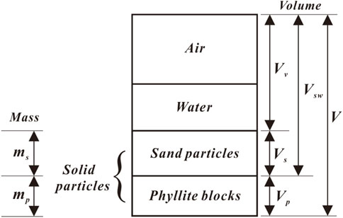
FIGURE 5. Three-phase diagram of phyllite bimrocks.
From Eq. 6, the mass of the phyllite blocks and sand matrix can be given as follows:
where
From Eq. 7, the mass of phyllite blocks and sand matrix with different block percentages can be calculated. The calculation results are listed in Table 1. To achieve the orientation of blocks in phyllite bimrock specimens, the specimen is divided into five layers in vertical, and each layer is 8 cm high. The schematic diagram of the specimens with different block percentages and block sizes is shown in Figure 6. Since the specimen is divided into five layers in vertical, the phyllite blocks and sand matrix are also divided into the same five parts in each specimen. The specimen preparation process is shown in Figure 7.
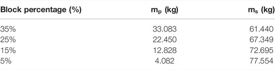
TABLE 1. Mass of phyllite blocks and sand matrix with different blocks percentage.
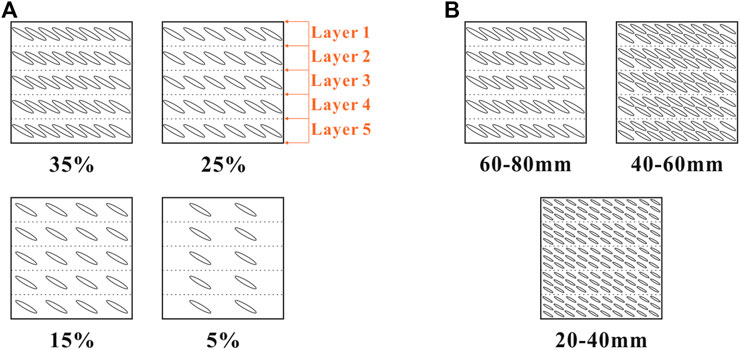
FIGURE 6. Schematic diagram of the specimens. (A) Group G-1 specimens; (B) Group G-2 specimens.
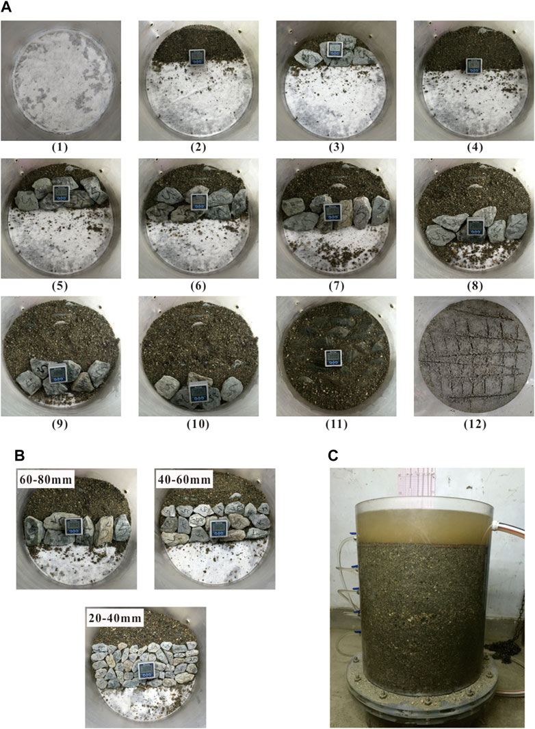
FIGURE 7. Specimen preparation process. (A) Preparation process of layer 5: Step 1–12; (B) Specimens with different blocks size; (C) phyllite bimrock specimens for permeability test.
Figure 7A shows the preparation process of layer 5 with a block percentage of 35% and the orientation angle (α) of 30°. The preparation process of layers 1–4 is similar to layer 5. Initially, a geotextile is placed on the perforated plate to prevent the sand particles from falling into the bottom of the seepage cylinder (Step 1). Then some sand particles are used to make a slope of 30° (Step 2), and several phyllite blocks are placed on the slope surface (Step 3). Finally, the phyllite blocks are covered with sand particles and then make a slope of 30° again (Step 4). Repeat steps 1–4 until the phyllite blocks are filled (Step 5–11), and then phyllite blocks are compressed to 8 cm in vertical (Step 12). Repeat steps 2–12, and the phyllite bimrock specimens can be prepared (Figure 7C). The preparation process of phyllite bimrock specimens with block percentages of 5%, 15%, and 25% is the same as the 35%. The specimen preparation process of different blocks size is similar to phyllite bimrock specimens with a block percentage of 35%, except that the phyllite blocks are replaced by the corresponding size. The phyllite bimrock specimens with different block sizes are shown in Figure 7B. All the phyllite blocks have the same orientation angle (α) of 30°, which is the special structure of phyllite bimrocks and is different from the other bimrocks.
Experimental Procedure
During the permeability test, the experimental steps are as follows:
1) Specimen saturation. After the preparation of the specimen, the water was injected to saturate the specimen. Each specimen was soaked for 3 h.
2) Experimental data recorded. After the specimen saturation was accomplished, the seepage water volume, permeability time and water head difference were recorded. It is worth noting that the volume of seepage water was measured twice for each hydraulic gradient at the given interval time (i.e., permeability time).
3) Calculation of the flow velocity, hydraulic gradient, and hydraulic conductivity. The flow velocity can be obtained based on the equation below:
where
The hydraulic gradient can be calculated by the following equation:
where
Results and Discussion
Flow Regime in Phyllite Bimrocks
To investigate the flow behavior of phyllite bimrocks, the Reynolds number (Re) is calculated in this paper. The Reynolds number (Re) can be calculated as:
where Re is the Reynolds number; v is the flow velocity; n is the porosity of the specimen;
In practice, Reynolds number (Re) can be used to judge the flow behavior of the porous media obeying Darcy’s law or non-Darcy’s law. Bear (1972) reported that if the value of Reynolds number (Re) is between 1 and 10, which is calculated by the average grain size
where
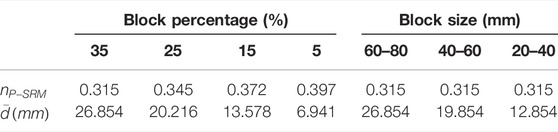
TABLE 2.
As shown in Eq. 10, n is the porosity of the specimen, which is equal to the porosity of the phyllite bimrock specimens
where
From Eq. 10 and Table 2, the range of Reynolds numbers has been obtained. The relationship between the Reynolds number and hydraulic gradient is shown in Figure 8.
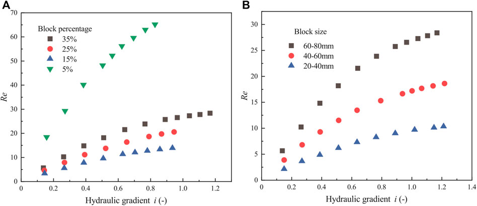
FIGURE 8. Relationship between hydraulic gradient and Reynolds number for phyllite bimrock specimens with different block percentages and block sizes considering the orientation of blocks. (A) Group G1 test; (B) Group G2 test.
Figure 8 shows that when block percentages are 35%, 25%, and 5% and block sizes are 60–80 and 40–60 mm, the non-Darcy’s flow is evident. Moreover, with the increase of the hydraulic gradient, the Reynolds number increases, and the flow regime becomes laminar to turbulent under a lower hydraulic gradient. However, when the block percentage is 15%, and the block size is 20–40 mm, it cannot be seen that the flow behavior is Darcy’s law or non-Darcy’s law. Generally speaking, Figure 8 illustrates that Darcy’s law can not apply to analyze the flow behavior of the phyllite bimrocks.
Hydraulic Gradient-Velocity Relationships
To further study the flow behavior of the phyllite bimrocks, the relationship between hydraulic gradient and flow velocity is studied. In previous studies, if the hydraulic gradient exists a positive correlation with the flow velocity, the flow behavior of porous media obeys Darcy’s law. However, if the hydraulic gradient has a non-linear relationship with the flow velocity, the flow behavior of porous media is regarded as the non-Darcy’s flow. In many publications, two empirical equations are frequently applied to analyze the flow behavior of porous media, which are the Forchheimer equation and the Izbash equation (Venkataraman and Rao, 1998; Bordier and Zimmer, 2000; Yamada et al., 2005; Sidiropoulou et al., 2007).
Forchheimer equation is known as quadratic correlations between flow velocity and hydraulic gradient. Forchheimer (1901) added a second order velocity term to the original Darcy equation representing the microscopic inertial effect in groundwater flow (Hansen, 1992), and the Forchheimer equation can be written as:
where A and B are called the Forchheimer coefficient;
It is assumed that the power relationship can be established by fitting the hydraulic gradient with the flow velocity. In that case, the Izbash equation can be used to evaluate the flow behavior of porous media, and the Izbash equation can be written as:
where a and b are called the Izbash coefficient;
To evaluate the flow behavior of phyllite bimrocks, the regression relationship of the hydraulic gradient and the flow velocity of phyllite bimrock specimens with different block percentages and block sizes considering the orientation of blocks are depicted in Figures 9, 10. Figure 9 shows i—v correlation using quadratic law (Forchheimer equation), and Figure 10 shows the power regression of i—v correlation (Izbash equation).
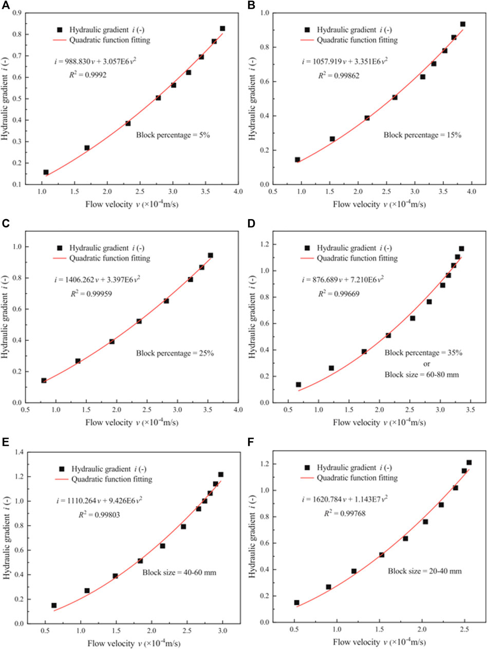
FIGURE 9. Relationship between the hydraulic gradient and the flow velocity by Forchheimer equation. (A–D) Plots for phyllite bimrocks with different block percentages of 5%, 15%, 25%, and 35%, respectively; (D–F) Plots for phyllite bimrocks with different block sizes of 60–80, 40–60, and 20–40 mm, respectively.
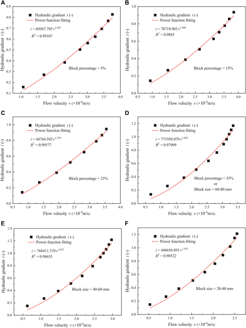
FIGURE 10. Relationship between the hydraulic gradient and the flow velocity by Izbash equation. (A–D) Plots for phyllite bimrocks with different block percentages of 5%, 15%, 25%, and 35%, respectively; (D–F) Plots for phyllite bimrocks with different block sizes of 60–80, 40–60, and 20–40 mm, respectively.
Figure 9 shows that the quadratic relationship can be established by fitting the hydraulic gradient with the flow velocity. The quadratic curve (Forchheimer equation) is in good agreement with the experimental data. Therefore, the flow behavior of phyllite bimrocks with different block percentages and block sizes considering the orientation of blocks does not obey Darcy’s law. Besides, compared with Figure 8, when the block percentage is 15% and the block size is 20–40 mm, the relationship between the hydraulic gradient and the flow velocity is not linear obviously. Therefore, it is clear that even though the Reynolds number is smaller, the flow behavior of phyllite bimrocks does not comply with Darcy’s law. Figure 10 shows that the power relationship (Izbach equation) can be established by fitting the hydraulic gradient with the flow velocity. To get a satisfactory result, the Forchheimer coefficients (A and B), Izbash coefficients (a and b) and the coefficient of regression (R2) are calculated, and the results are shown in Table 3.
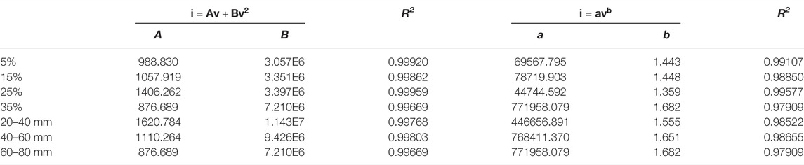
TABLE 3. Values of Forchheimer coefficients (A and B), Izbash coefficients (a and b) and the coefficient of regression (R2) for phyllite bimrocks with different block percentages and block sizes under the same orientation angle (α).
It can be seen from Table 3 that whether the Forchheimer equation or Izbash equation, the experimental data has a good correlation. However, R2 obtained by fitting the Forchheimer equation is larger than 0.995, while R2 obtained by fitting the Izbach equation is less than 0.995 (except blocks percentage = 25%). Therefore, compared with the Izbach equation, the Forchheimer equation can be better used to analyze the relationship between hydraulic gradient and the flow velocity of the phyllite bimrocks.
In summary, the presented results show that Darcy’s law is not available to determine the flow behavior of phyllite bimrocks with different block percentages and block sizes considering the orientation of blocks, but it can be better analyzed by the Forchheimer equation.
Hydraulic Conductivity of Phyllite Bimrocks
As mentioned before, the Forchheimer equation gives more satisfactory results relative to the Izbash equation. Thus, in this section, the hydraulic conductivity of phyllite bimrocks with different block percentages and block sizes considering the orientation of blocks is calculated using the Forchheimer equation. For the Forchheimer coefficient A, Zeng and Grigg (2006) evaluate by the following expression:
where A is the Forchheimer coefficient;
In addition, the hydraulic conductivity
where
From the Eqs 15, 16, the following equation can be obtained:
where
Based on Eq. 17 and Table 3, the hydraulic conductivity
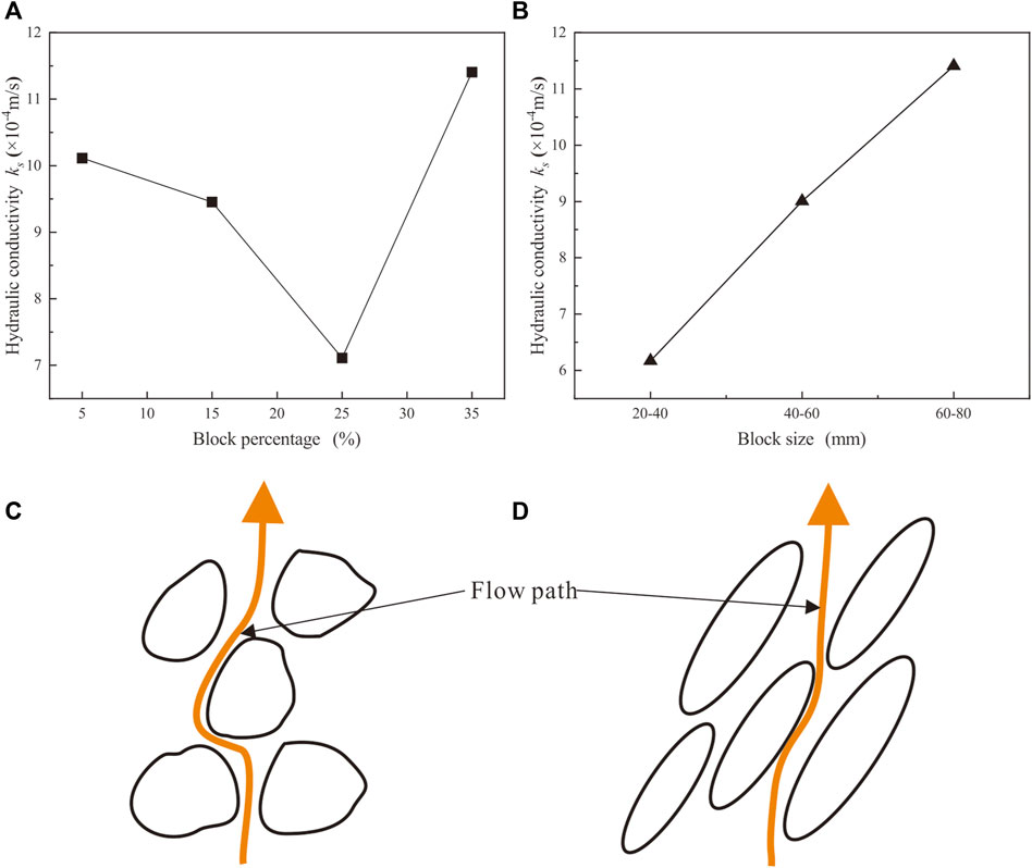
FIGURE 11. Hydraulic conductivity of phyllite bimrocks with different block percentages (A) and block sizes (B) considering the orientation of blocks, and the flow paths in the homogeneous bimrocks (C) and the phyllite bimrocks (D).
Figure 11A plots hydraulic conductivity against block percentage considering the orientation of blocks. With the increase in block percentage, the hydraulic conductivity firstly decreases to the minimum and then increases, and the minimum of hydraulic conductivity is the percentage of the block of 25%. The result is in disagreement with Dunn and Mehuys (1984) and Liao (2004). Their research shows that the hydraulic conductivity constantly decreases with the increase in the rock blocks. The inconsistency of the result may have been due to the relative waterproof of phyllite blocks and the permeability of block-sand interfaces. Compared with the sand matrix, the phyllite blocks are relatively waterproof and reduce the effective flow cross section, which means the effective porosity in phyllite bimrocks decreases. Therefore, the porosity of phyllite bimrock specimens decreases (see Table 2), resulting in the hydraulic conductivity decreasing with the block percentage increase. Nevertheless, because the phyllite blocks are relatively waterproof, when the seepage water flows through the phyllite bimrocks, it prefers to flow along the surface of phyllite blocks rather than in the sand matrix. The hydraulic pressure decreases sharply at the block-sand interfaces, and the permeability of block-sand interfaces increases accordingly. Thus, the permeability property of phyllite bimrocks increases as increasing the block percentage. Consequently, combined with the two influencing factors, the result shows that the hydraulic conductivity of the phyllite bimrocks firstly increases and then decreases. When the block percentage is less than 25%, the relative waterproof of phyllite blocks is dominant, and the hydraulic conductivity decreases with the increase of the block percentage. However, when the block percentage is larger than 25%, the high permeability of block–sand interfaces leads to increased hydraulic conductivity as the block percentage increases.
During the permeability test conducted by Wang et al. (2016a), the trend of block percentage against hydraulic conductivity is roughly similar to the result in this paper. However, Wang et al. (2016a) presented that the hydraulic conductivity reaches the minimum when the block percentage is 40%. The reason why the results are different is that the orientation of blocks is ignored. Compared with the homogeneous bimrocks (Figures 11C,D), the flow paths in the phyllite bimrocks decrease due to the orientation of blocks. The orientation of blocks further enhances the permeability property of block-sand interfaces, and the hydraulic conductivity reaches its minimum when the block percentage is smaller.
Figure 11B shows that hydraulic conductivity increases approximately linear with the increase in block size. In this paper, the relationship between hydraulic conductivity and block size is contrary to Shafiee (2008) and Gutierrez and Vallejo (2013). The reason for the difference is that the orientation of blocks is considered in this paper. As mentioned earlier, the permeability of block-sand interfaces is larger than the sand matrix. When the block size increases, the permeability of block-sand interfaces increases accordingly. Besides, the orientation of blocks reduces the actual flow paths in the phyllite bimrocks. Under the combined effect of larger permeability of block-sand interfaces and shorter flow path, the permeability property of phyllite bimrocks has been significantly enhanced. Therefore, the hydraulic conductivity of phyllite bimrocks goes up with the increase in block size.
Determine of Forchheimer Equation Coefficients A and B
Based on the results of section 3.2, it was found that the flow behavior of the phyllite bimrocks does not comply with Darcy’s law and the Forchheimer equation can be better used to analyze the flow behavior of the phyllite bimrocks. In 1901, Forchheimer presented the quadratic equation after the experimental test. However, the effects of the physical and mechanical properties of porous media on Forchheimer coefficients A and B have not been studied. After that, many scholars and engineers are interested in determining the Forchheimer coefficient A and B. For the A and B, Ergun (1952) suggested the following expressions:
where A and B are the Forchheimer coefficient; n is the porosity of the porous media; d is the particle size; g is the gravity acceleration and
Kovacs (1981) derived the following expressions of Forchheimer coefficient A and B:
where A and B are the Forchheimer coefficient; n is the porosity of the porous media; d is the particle size; g is the gravity acceleration and
Fand and Thinakaran (1990) present the following expressions of Forchheimer coefficients A and B:
where A and B are the Forchheimer coefficient; n is the porosity of the porous media; d is the particle size; g is the gravity acceleration; M is a function of A and B and
Furthermore, a similar approach of Forchheimer coefficient A and B has also been suggested by Kadlec and Knight (1996):
where A and B are the Forchheimer coefficient; n is the porosity of the porous media; d is the particle size; g is the gravity acceleration and
The above expressions for A and B are representative examples in the publication. It can be seen that the Forchheimer coefficient A and B have closely relevant to the particle size and porosity. As mentioned before, block percentage is closely related to the porosity of the phyllite bimrocks
Accordingly, based on the Eqs 18–21, Forchheimer coefficients A and B are defined by the following expressions in this paper:
where A1 and B1 are the constant value. A and B are the testing values (Table 3);
To determine the Forchheimer coefficients A and B, the normalized objective function (NOF) criterion is used in this paper. The NOF is the ratio between the Root Mean Square Error (RMSE) and the overall mean X of the testing data. The NOF, RMSE, and X can be calculated as follows (Moutsopoulos et al., 2009):
where xi are the testing values of A and B (see Table 3); yi are the calculation values by Eq. 22; N is the total number of values. To get the best match, NOF must be less than 1.0. When the NOF is less than 1.0, the theoretical method is still reliable. The computed results are shown in Table 4.

TABLE 4. Constant values through NOF analysis.
As shown in Table 4, the calculated values of NOF(B1) are closer to 0.0 than that of NOF(A1), especially for the block size of 60–80 mm. For the block percentage, when the block percentage is 5%, both NOF(A1) and NOF(B1) are less than 1.0, which indicates that A1 = 988.830 and B1 = 3.057E6 can be used to determine the value of A and B roughly. For the block size, except the block size is 60–80 mm, NOF(A1) and NOF(B1) are less than 1.0. When the block size is 40–60 mm, the A1 = 1110.264 and B1 = 9.426E6 can be adopted to estimate the value of A and B. Therefore, Forchheimer coefficients A and B can be expressed as follows in this paper:
where
Eq. 26 and Eq. 27 are suitable for describing the flow behavior of phyllite bimrocks with different block percentages and block sizes considering the orientation of blocks, respectively. In addition, it is worth noting that these two flow laws have strict applicable conditions. First, it can not be applied to other bimrocks, only the phyllite bimrocks. Second, the orientation angle of the phyllite rock must be 30°, and other orientation angles are not suitable. Third, the compaction degree must be 80%, i.e., the porosity of the sand matrix must be constant. Consequently, these two flow laws have a narrow scope of application. In the following research, these problems will be figured out.
Conclusion
The coupling characteristics of flow and orientation of blocks in phyllite bimrocks were studied by conducting a series of permeability tests. Based on the Reynolds number, the flow regime of phyllite bimrocks is determined. Besides, the hydraulic conductivity of phyllite bimrocks with different percentages and sizes was investigated. The results show that the orientation of blocks significantly affects the flow behavior of phyllite bimrocks. However, the explanation of the effect of the orientation of blocks on the permeability property is insufficient. Furthermore, the normalized objective function (NOF) criterion was used to estimate the optimized empirical flow behavior formulas of the phyllite bimrocks. Based on experimental data and analysis, the following conclusions can be drawn:
1) The flow regime of the phyllite bimrocks becomes laminar to turbulent under lower hydraulic gradient, and the Reynolds number indicates that Darcy’s law is incapable of analyzing the flow behavior of the phyllite bimrocks.
2) The relationship between the hydraulic gradient and the flow velocity shows that the Forchheimer equation and Izbash equation are available to analyze the flow behavior of the phyllite bimrocks. Besides, through comparison analysis, the Forchheimer equation is better at determining the flow behavior of phyllite bimrocks than the Izbash equation.
3) Based on the Forchheimer equation, the hydraulic conductivity of phyllite bimrocks is discussed. When the block percentage increases to 25%, the hydraulic conductivity reaches the minimum. When the block percentage exceeds 25%, the hydraulic conductivity increases again. Compared with other research, the orientation of blocks leads to a decrease in the block percentage at the minimum hydraulic conductivity. Moreover, hydraulic conductivity increases approximately linearly with the increase of block size.
4) On the basis of previous studies, the Forchheimer equation with estimated Forchheimer coefficients A and B applied to describe the flow behavior of phyllite bimrocks is obtained and validated through NOF analysis.
Data Availability Statement
The original contributions presented in the study are included in the article/supplementary material, further inquiries can be directed to the corresponding author.
Author Contributions
YW and XZ designed the research. YW, XZ, SL, and CZ performed the research. YW, XZ, GZ, and BW analyzed the date. YW, XZ, and GZ wrote the manuscript.
Funding
This study was supported by the National Natural Science Foundation of China (Grant No. 41672295), the Science and Technology Project of the Department of Transportation of the Sichuan Province (Grant No. 2015B1-1), the Sichuan Provincial Science and Technology Plan Project (Grant No. 2017JY0264) and the Major Systematic Project of Science and Technology Plan of China Railway Corporation (Grant No. P2018G047).
Conflict of Interest
Aurthor GZ is employed by China Railway Eryuan Engineering Group Co., Ltd.
The remaining authors declare that the research was conducted in the absence of any commercial or financial relationships that could be construed as a potential conflict of interest.
Publisher’s Note
All claims expressed in this article are solely those of the authors and do not necessarily represent those of their affiliated organizations, or those of the publisher, the editors and the reviewers. Any product that may be evaluated in this article, or claim that may be made by its manufacturer, is not guaranteed or endorsed by the publisher.
Acknowledgments
We thank our friends and colleagues for their invaluable advice, assistance, and support during the experiments and data acquisition.
References
Bordier, C., and Zimmer, D. (2000). Drainage Equations and Non-darcian Modeling in Coarse Porous Media or Geosynthetic Materials. J. Hydrol. 228 (3), 174–187. doi:10.1016/S0022-1694(00)00151-7
Chen, X.-b., Li, Z.-y., and Zhang, J.-s. (2014). Effect of Granite Gravel Content on Improved Granular Mixtures as Railway Subgrade Fillings. J. Cent. South Univ. 21 (8), 3361–3369. doi:10.1007/s11771-014-2310-z
Chen, Z., and Song, D. (2021). Numerical Investigation of the Recent Chenhecun Landslide (Gansu, China) Using the Discrete Element Method. Nat. Hazards 105 (1), 717–733. doi:10.1007/s11069-020-04333-w
DL/T5356-2006 (2006). National Development and Reform Commission of the People’s Republic of China: Code for Coarse-Grained Soil Tests for Hydropower and Water Conservancy Engineering. Beijing: DL/T 5356-2006.
Du, H., Song, D., Chen, Z., and Guo, Z. (2020). Experimental Study of the Influence of Structural Planes on the Mechanical Properties of Sandstone Specimens under Cyclic Dynamic Disturbance. Energy Sci. Eng. 8 (11), 4043–4063. doi:10.1002/ese3.794
Dunn, A., and Mehuys, G. (1984). Relationship between Gravel Content of Soils and Saturated Hydraulic Conductivity in Laboratory Tests. Soil. Sci. Soc. Am. J. 48 (3), 736–740. doi:10.2136/sssaspecpub13.c6
Fand, R. M., and Thinakaran, R. (1990). The Influence of the Wall on Flow through Pipes Packed with Spheres. J. Fluids Eng.-Trans. ASME 112 (1), 84–88. doi:10.1115/1.2909373
GB/T50123-2019 (2019). “Ministry of Water Resources of the People’s Republic of China,” in Standard for Geotechnical Testing Method (Beijing: GB/T 50123-2019).
Gutierrez, J. J., and Vallejo, L. E. (2013). Laboratory Experiments on the Hydraulic Conductivity of Sands with Dispersed Rock Particles. Geotech. Geol. Eng. 31 (4), 1405–1410. doi:10.1007/s10706-013-9652-4
Hansen, D. (1992). The Behavior of Flowthrough Rockfill Dams. Ph.D. Dissertation. Ottawa, Ontario: Department of Civil Engineering, University of Ottawa.
Herrera, N. M., and Felton, G. K. (1991). Hydraulics of Flow through a Rockhll Dam Using Sediment-free Water. Trans. ASAE 34 (3), 0871–0875. doi:10.13031/2013.31742
Indrawan, I. G. B., Rahardjo, H., and Leong, E. C. (2006). Effects of Coarse-Grained Materials on Properties of Residual Soil. Eng. Geol. 82 (3), 154–164. doi:10.1016/j.enggeo.2005.10.003
Kalender, A., Sonmez, H., Medley, E., Tunusluoglu, C., and Kasapoglu, K. E. (2014). An Approach to Predicting the Overall Strengths of Unwelded Bimrocks and Bimsoils. Eng. Geol. 183, 65–79. doi:10.1016/j.enggeo.2014.10.007
Liao, Q. L. (2004). Geological Origin and Structure Model of Rock and Soil Aggregate and Study on its Mechanical and MH Coupled Properties. PhD dissertation. Beijing: Institute of Geology and Geophysics, Chinese Academy of Science.
Lin, Y., Peng, L., Lei, M., Wang, X., and Cao, C. (2019). Predicting the Mechanical Properties of Bimrocks with High Rock Block Proportions Based on Resonance Testing Technology and Damage Theory. Appl. Sci. 9 (17), 3537. doi:10.3390/app9173537
Liu, F., Mao, X., Fan, Y., Wu, L., and Liu, W. V. (2020). Effects of Initial Particle Gradation and Rock Content on Crushing Behaviors of Weathered Phyllite Fills - A Case of Eastern Ankang Section of Shiyan-Tianshui Highway, China. J. Rock Mech. Geotechnical Eng. 12 (2), 269–278. doi:10.1016/j.jrmge.2019.07.011
Medley, E., and Goodman, R. E. (1994). “Estimating the Block Volumetric Proportions of Melanges and Similar Block-In-Matrix Rocks (Bimrocks),” in 1st North American Rock Mechanics Symposium. Editors P. P. Nelson, and S. E. Laubach (Austin, Texas, 851–858.
Medley, E., and Lindquist, E. S. (1995). “The Engineering Significance of the Scale-Independence of Some Franciscan Melanges in California, USA,” in Proceedings of the 35th US Rock Mechanics Symposium. Editors J. K. Daemen, and R. A. Schultz (Rotterdam: Balkema), 907–914.
Medley, E. (1994). The Engineering Characterization of Melanges and Similar Block-In-Matrix Rocks (Bimrocks). PhD dissertation. Berkeley: University of California.
Moutsopoulos, K. N., Papaspyros, I. N. E., and Tsihrintzis, V. A. (2009). Experimental Investigation of Inertial Flow Processes in Porous Media. J. Hydrology 374 (3–4), 242–254. doi:10.1016/j.jhydrol.2009.06.015
Shafiee, A. (2008). Permeability of Compacted Granule-Clay Mixtures. Eng. Geol. 97 (7), 199–208. doi:10.1016/j.enggeo.2008.01.002
Shakoor, A., and Cook, B. D. (1990). The Effect of Stone Content, Size, and Shape on the Engineering Properties of a Compacted Silty Clay. Environ. Eng. Geoscience xxvii (2), 245–253. doi:10.2113/gseegeosci.xxvii.2.245
Sidiropoulou, M. G., Moutsopoulos, K. N., and Tsihrintzis, V. A. (2007). Determination of Forchheimer Equation Coefficientsa Andb. Hydrol. Process. 21 (4), 534–554. doi:10.1002/hyp.6264
Song, D., Liu, X., Huang, J., and Zhang, J. (2020). Energy-based Analysis of Seismic Failure Mechanism of a Rock Slope with Discontinuities Using Hilbert-Huang Transform and Marginal Spectrum in the Time-Frequency Domain. Landslides 18 (1), 105–123. doi:10.1007/s10346-020-01491-7
Song, D., Liu, X., Li, B., Zhang, J., and Bastos, J. J. V. (2021). Assessing the Influence of a Rapid Water Drawdown on the Seismic Response Characteristics of a Reservoir Rock Slope Using Time-Frequency Analysis. Acta Geotech. 16 (4), 1281–1302. doi:10.1007/s11440-020-01094-5
Soni, J. P., Islam, N., and Basak, P. (1978). An Experimental Evaluation of Non-darcian Flow in Porous Media. J. Hydrol. 38 (3), 231–241. doi:10.1016/0022-1694(78)90070-7
Tong, Z. X. (1984). Subdivisions of the Maoxian Group in Jiudingshan of Maowen District, Sichuan and the Brachiopoda Faunae. Stratigr. Paleontol. 01, 59–69.
Venkataraman, P., and Rao, P. R. M. (1998). Darcian, Transitional, and Turbulent Flow through Porous Media. J. Hydraulic Eng. 124 (8), 840–846. doi:10.1061/(asce)0733-9429(1998)124:8(840)
Wan, Y., Zhao, X., Wünnemann, B., Ling, S., and Zeng, C. (2022). Flow Behavior of Phyllite Bimrocks Having the Orientation of Blocks. Arab. J. Geosci. 15, 860. doi:10.1007/s12517-022-10026-4
Wang, Y., Li, X., Zheng, B., Zhang, Y. X., Li, G. F., and Wu, Y. F. (2016a). Experimental Study on the Non-darcy Flow Characteristics of Soil-Rock Mixture. Environ. Earth Sci. 75 (9), 756. doi:10.1007/s12665-015-5218-5
Wang, Y., Li, X., Zheng, B., and Ma, C. F. (2016b). An Experimental Investigation of the Flow-Stress Coupling Characteristics of Soil-Rock Mixture under Compression. Transp. Porous Med. 112 (2), 429–450. doi:10.1007/s11242-016-0653-7
Wang, Y., Zheng, S., Wang, Y., and Guo, Y. (2021). Experimental Study on the Permeability and Seepage Characteristics of Bimsoils. Geomatics, Nat. Hazards Risk 12 (1), 3001–3020. doi:10.1080/19475705.2021.1987341
Xiang, X. C., and Jiang, G. S. (2011). “Effects of Large Rock Particles on Permeability of Soil and Rock Mixture,” in Proceeding of the 1st International Conference on Civil Engineering, Architecture and Building Materials, Haikou, China, 1804–1807.
Xu, W. J., Qiang, X., and Rui-Lin, H. (2011). Study on the Shear Strength of Soil-Rock Mixture by Large Scale Direct Shear Test. Int. J. Rock Mech. Min. Sci. 48 (8), 1235–1247. doi:10.1016/j.ijrmms.2011.09.018
Xu, G., He, C., Su, A., and Chen, Z. (2018). Experimental Investigation of the Anisotropic Mechanical Behavior of Phyllite under Triaxial Compression. Int. J. Rock Mech. Min. Sci. 104, 100–112. doi:10.1016/j.ijrmms.2018.02.017
Xu, W. J., and Hu, R. L. (2006). Particle Size Fractal Characteristics of the Soil-Rock Mixtures in the Right Bank Slope of Jinsha River at Long-Pan, Tiger-Leaping Gorge Area. J. Eng. Geol. 14 (4), 496–501.
Xu, W. J., and Wang, Y. G. (2010). Meso-structural Permeability of S-RM Based on Numerical Tests. Chin. J. Geotechnical Eng. 32 (4), 543–550.
Yamada, H., Nakamura, F., Watanabe, Y., Murakami, M., and Nogami, T. (2005). Measuring Hydraulic Permeability in a Streambed Using the Packer Test. Hydrol. Process. 19 (13), 2507–2524. doi:10.1002/hyp.5688
Yu, W. (2021). “Macro–meso Geomechanical Behaviors of Bimrocks,” in Geomechanical Behaviors of Bimrocks (Science Press), Beijing, 1–35. doi:10.1201/9781003155478
Zanker, A. (1972). Nomograph for Hydraulic Conductivity and Intrinsic Permeability of Water-Soil System. Soil Sci. 113 (5), 375–377. doi:10.1097/00010694-197205000-00013
Zeng, Z., and Grigg, R. (2006). A Criterion for Non-darcy Flow in Porous Media. Transp. Porous Med. 63 (1), 57–69. doi:10.1007/s11242-005-2720-3
Zhou, Z., Fu, H. L., Liu, B. C., Tan, H. H., and Long, W, X. (2006). Orthogonal Tests on Permeability of Soil-Rock-Mixture. Chin. J. Geotechnical Eng. 28 (9), 1134–1138.
Keywords: bimrocks, block percentage, block size, flow behavior, hydraulic conductivity, Reynolds number
Citation: Wan Y, Zhao X, Zhang G, Wünnemann B, Ling S and Zeng C (2022) Experimental Study on Non-Darcian Flow in Phyllite Bimrocks With the Orientation of Blocks. Front. Earth Sci. 10:888975. doi: 10.3389/feart.2022.888975
Received: 03 March 2022; Accepted: 01 June 2022;
Published: 29 June 2022.
Edited by:
Chong Xu, Ministry of Emergency Management, ChinaReviewed by:
Ming Zhang, China University of Geosciences Wuhan, ChinaDanqing Song, Tsinghua University, China
Aiguo Xing, Shanghai Jiao Tong University, China
Copyright © 2022 Wan, Zhao, Zhang, Wünnemann, Ling and Zeng. This is an open-access article distributed under the terms of the Creative Commons Attribution License (CC BY). The use, distribution or reproduction in other forums is permitted, provided the original author(s) and the copyright owner(s) are credited and that the original publication in this journal is cited, in accordance with accepted academic practice. No use, distribution or reproduction is permitted which does not comply with these terms.
*Correspondence: Xiaoyan Zhao, eHl6aGFvMkBzd2p0dS5lZHUuY24=