 XiYan Bao1
 JinYang Lv
- 1Jiangsu Provincial Transportation Department, Nanjing, China
- 2China Design Group Co., Ltd., Nanjing, China
- 3Hohai University, Nanjing, China
In soft soil regions, the construction of irregular-shaped excavations can readily disturb the underlying soft clay, leading to alterations in soil properties that, in turn, cause significant deformations of the excavation support structure. These deformations can compromise both the excavation’s stability and the surrounding environment. Based on a large-scale, irregular-shaped excavation project for an underground interchange in a soft soil area, numerical simulations were performed using Midas GTS to analyze the overall foundation pit deformationn. The study explored the effects of groundwater lowering, excavation, and local seepage on the disturbance of surrounding soils and the resulting foundation pit deformationn. The findings reveal that the irregular-shaped excavation exhibits distinctive spatial deformation characteristics, with the arcuate retaining structure’s “arching” effect reducing the diaphragm wall’s horizontal displacement. Groundwater lowering exerts a stronger disturbance on shallow soils near the excavation and a weaker disturbance on deeper soils. Excavation-induced stress redistribution notably affects the soils above the excavation surface and those within the embedded region of the support structure. Local seepage primarily disturbs the soils surrounding the leakage point. Additionally, the weakening of soil parameters significantly influences the foundation pit deformationn. Combined disturbance (dewatering + excavation + leakage) induced 32%, 45%, and 58% greater displacements compared to individual factors, confirming the critical role of multi-factor coupling effects.
1 Introduction
With the advancement of urban underground transportation infrastructure, the importance of large-scale underground interchange projects has become increasingly prominent. These projects often involve large, irregularly shaped excavations. When designing support systems for such excavations, analytical methods are often inadequate due to the complexity of the calculations. Moreover, these excavations are typically associated with imbalanced soil pressure distributions and stress concentration within the support structures (Abbas et al., 2023; Wu, 2022). Understanding the factors influencing the deformation of irregular-shaped excavations is of significant importance. Xu et al. (2010) conducted a sensitivity analysis of soil parameters for an “8”-shaped excavation using numerical simulations. Their study highlighted that variations in soil parameters considerably impacted on the internal forces within the excavation’s support structure. However, their M-C model proved less suitable for modeling the minor strains in the soil induced by excavation. Liu B. et al. (2023) studied the “size effect” on deformation using a super-large excavation case from the Yangtze River floodplain region. Their findings indicated that the excavation’s length-to-width ratio significantly affected the horizontal displacement of the retaining wall and ground settlement. Liu N. W. et al. (2023) examined the deformation behavior during the excavation of a minor, ultra-deep excavation in Hangzhou, concluding that horizontal displacement and ground settlement were notably smaller than in similar excavation projects.
In the study of deformation in irregularly shaped excavations and surrounding soil disturbance within high-sensitive soft clay regions, the critical factors influencing excavation deformation include the high compressibility, low strength, and rheological properties of soft clays (Bai et al., 2023; Zhou et al., 2019). Recent innovations proposed by Karkush and Yassin (2020), Saba and Mahdi (2023) introduce sustainable material modification strategies to improve soft soil mechanical performance, providing engineering references for disturbance control. Contrasting with brittle fracture studies of rock-like materials (Zhao et al., 2020; Yunteng et al., 2016), crack propagation mechanisms offer theoretical insights into the progressive damage processes of soft clays. Regarding numerical simulation, the extended nonlocal state-based peridynamics method developed by Wang (2018) demonstrates unique advantages in analyzing 3D stress distributions of irregular excavations. Additionally, Bouali et al. (2021) revealed correlations between retaining structure deformation patterns and passive earth pressure distributions through soil pressure tests. Current research has established a “material modification - numerical simulation - field monitoring” multiscale framework, though asymmetric deformations and disturbance effects induced by irregular excavations still require further investigation. Tunnel excavation induces soil disturbance, leading to deformation of adjacent pipelines (Shi et al., 2025; Shi et al., 2024).
The issue of seepage in excavation pits is also a significant factor contributing to excavation safety problems (Wang et al., 2018; Duan et al., 2016). Seepage not only leads to erosion and damage of the pit’s supporting structures but also disturbs the surrounding soil, reducing of its strength. Liu J.-C. et al. (2023) investigated various complex conditions of seepage in excavation pits and concluded that seepage leads to a sudden increase in horizontal displacement of the pit’s diaphragm walls and settlement of the surrounding ground. The extent of the impact varies depending on the location of the seepage, which warrants further investigation. Deng et al. (2023), using the case of a water inflow incident in an excavation pit located in Nanjing, which involved sandy layers and deep confined aquifers, analyzed the disturbance to the surrounding soil caused by seepage. They found that seepage significantly reduces the strength parameters (c, φ).
The present study uses a large-scale underground interchange project with an irregular-shaped excavation pit in the lower Yangtze River region, where silty clay is predominant, as a case study. Numerical simulations of the construction process are conducted, based on changes in the pore water pressure and stress redistribution around the excavation. The study analyzes the disturbance effects of excavation on the surrounding soil. Different seepage locations are selected by combining field monitoring feedback and the stress characteristics of the supporting structures. The impact of soil disturbance on the deformation of the irregular-shaped excavation pit under various seepage conditions is then examined.
2 Project overview
The excavation pit for the ramp section of an underground interchange bridge in a large-scale underground interchange project located in the lower Yangtze River region features a rectangular segment with a length of 23 m and a width of 15 m, as well as a curved ramp section with a maximum width of 30 m. The excavation depth of the pit is 13 m, and the overall shape of the excavation is a gradually transforming arc, characteristic of a large, irregular-shaped pit, as shown in Figure 1. The pit support system consists of bored pile walls with horizontal internal bracing. As presented in Figure 1 a 600 mm thick TRD (Trenchless Reconstruction Drilling) waterproof curtain is installed around the pit. The bored piles have a diameter of 800 mm and are spaced 1,000 mm apart. The first concrete support is designed with a cross-section of 800 mm × 800 mm, made of C35 concrete. The second and third stages of bracing use steel supports, with a steel pipe diameter of 609 mm and a wall thickness of 16 mm, made of Q235 steel. Due to the constraints imposed by the surrounding environment, the dewatering scheme involves the use of good points within the pit, with well spacing set at 9 m.
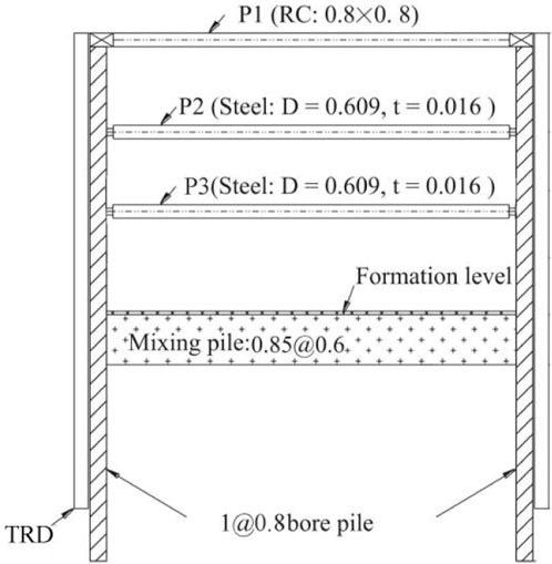
Figure 1. Cross-sectional schematic diagram of excavation.
The excavation pit is located in the plain region of the lower Yangtze River, with the soil parameters provided in Table 1. Stable groundwater levels measured in the field were 0.7–1.3 m below ground surface. Within the excavation depth range is a 12-m thick layer of silty clay, which exhibits high compressibility and is prone to significant deformation during excavation. This soil layer has a high moisture content and poor permeability, which increases the difficulty of dewatering the excavation pit. Additionally, the thixotropic nature of the silty clay results in a substantial reduction in soil strength after excavation disturbance, compared to the design strength values. These characteristics present additional challenges for the design and construction of the excavation pit.
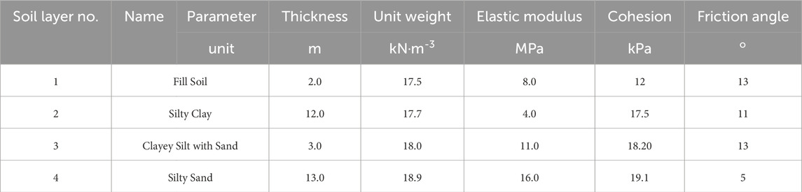
Table 1. Main soil parameters.
3 Simulation of excavation pit pile deformation
3.1 Midas model setup
The simulation and analysis were conducted using the Midas GTS NX finite element software, based on geological survey data. The soil model employs the modified Mohr-Coulomb criterion, with parameters derived from the geological survey and referencing the study by Wang (2018), as shown in Table 2. TAccording to field construction feedback, bored cast-in-place piles exhibit plumpness coefficients ranging from 1.1 to 1.2, indicating good quality. These piles are therefore analyzed according to design standards. To simplify calculations, bored piles are modeled as equivalent diaphragm walls with an effective thickness of 0.8 m and elastic modulus of 25 GPa. In the model, diaphragm walls are modeled using 2D plate elements while impermeable interface elements are extracted outside to simulate cutoff curtains. Crown beams, wales, and internal braces are represented by 1D beam elements. To ensure nodal coupling between diaphragm wall elements and wale nodes, wale and crown beam elements are extracted and generated based on diaphragm wall element coordinates. To mitigate the influence of model size on the results, According to the study by Yin et al. (Duan et al., 2016), the distance from the excavation edge to the model boundary is set to 30 m, approximately 2.5 times the excavation depth. The model depth is set to 40 m.Based on field groundwater level investigations, the groundwater level is set to -1m, representing its annual mean value. The construction stages are divided into incremental soil excavation within the pit, with the groundwater level lowered to 1 m below the excavation depth before each stage. The dewatering phase is modeled as a transient simulation. Normal constraints are applied along the model’s perimeter, while vertical constraints are imposed at the base. The mesh generation and internal support layout are illustrated in Figure 2.
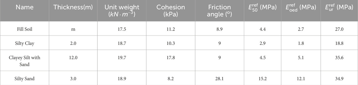
Table 2. Parameters of the modified Mohr-Coulomb model.
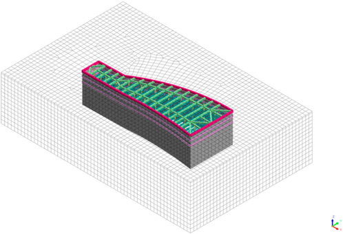
Figure 2. Mesh discretization of the model.
3.2 Analysis of foundation pit deformationn pile structure
The calculation was performed using Midas GTS NX, and the overall deformation of the equivalent diaphragm wall is shown in Figure 3. The maximum horizontal displacement of the equivalent diaphragm wall is 43 mm, corresponding to 0.3% of the excavation depth (H). To minimize the influence of mesh size on calculation results, four mesh sizes (5 m, 4 m, 3 m, and 2 m) were selected for computational analysis, using the diaphragm wall displacements on both sides of the foundation pit and the maximum surface settlement as indicators to evaluate the calculation results. As shown in Table 3, when the mesh size was 4 m or 5 m, the results exhibited significant fluctuations, indicating inadequate accuracy of the calculation results under these conditions. Conversely, as the mesh size decreased to 3 m, the calculation results stabilized. Considering computational efficiency, a mesh size of 3 m was selected for subsequent calculations. Due to the larger width of the excavation’s arcuate section, the stiffness loss of the horizontal internal supports is more significant, and the volume of soft clay, which experiences strength reduction due to unloading at the bottom of the pit, is larger. Consequently, the horizontal displacement of the pile in the arcuate section is greater, while the deformation in the rectangular section is smaller. In the arcuate section, the deformation on the side of the larger curvature is smaller than that on the smaller curvature side, and the maximum horizontal displacement of the diaphragm wall on the larger curvature side is closer to the rectangular section. On the smaller curvature side, the region with greater horizontal displacement of the diaphragm wall is nearer the wider end. Based on the excavation shape, the “arching” effect of the diaphragm wall in the arcuate section with larger curvature increases its stiffness, reducing horizontal displacement. On the larger curvature side, the increase in the horizontal width of the excavation leads to a more significant change in the section shape, resulting in stress concentration and an increase in horizontal displacement, accompanied by horizontal displacement at the pile top.
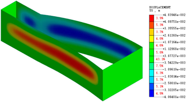
Figure 3. Horizontal displacement of the diaphragm wall.
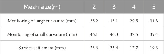
Table 3. The influence of mesh size on calculation results.
The strata below the excavation surface are composed of higher-strength Clayey Silt with Sand layers, while those above consist of weaker Silty Clay. This stratigraphic configuration restricts horizontal displacements at the foundation base, resulting in the maximum horizontal displacement shifting toward the mid-section of the excavation face.
The horizontal displacement of the diaphragm wall at the section with the maximum deformation was extracted to validate the numerical model, as shown in Figure 4. Above the excavation surface is a 12 m thick layer of weak, muddy clay, while the silty sand and sandy silt at the bottom of the pit exhibit better properties and provide strong anchorage for the deep diaphragm wall. As a result, the deformation of the diaphragm wall follows a fixed-end type behavior. With increasing excavation depth, the location of the maximum displacement of the diaphragm wall shows a clear trend of progressing deeper. Upon completion of the excavation, the maximum horizontal displacement of the diaphragm wall occurs near the pit bottom. As the excavation depth increases, the horizontal displacement of the diaphragm wall gradually increases, which aligns with typical patterns. When excavation is completed, the maximum horizontal displacement of the diaphragm wall reaches 46 mm.
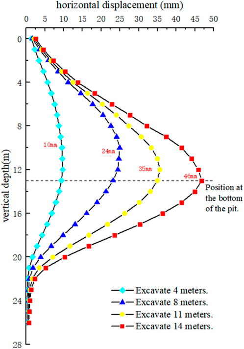
Figure 4. Diaphragm wall horizontal displacement by excavation stage.
The horizontal displacement results of the diaphragm wall at the region of maximum deformation from the numerical simulation were compared with the actual inclinometer monitoring data, as shown in Figure 5. The results indicate that the deformation pattern from the numerical simulation closely resembles the monitored data, with both showing a fixed-end type of deformation. The diaphragm wall deformation is more pronounced on the side of the excavation with smaller curvature, and the maximum deformation region occurs near the pit bottom in both cases. However, the maximum deformation observed in the actual case was 154 mm, corresponding to 1.2% of the excavation depth, and partial “kick-out” deformation was also noted. The displacement at the base of the diaphragm wall reached 11.6 mm.
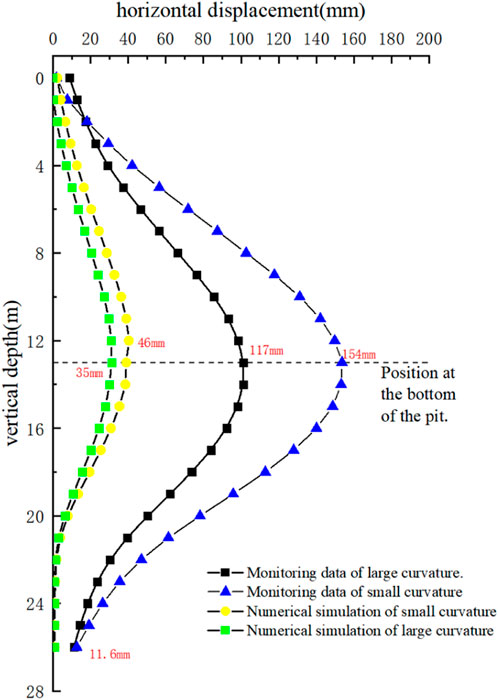
Figure 5. Comparison of diaphragm wall displacement and monitoring data.
3.3 Analysis of factors contributing to large deformations in the excavation
Based on engineering monitoring data and feedback from site inspections, as well as an analysis of the engineering geological parameters, the following factors are identified as contributing to the large deformations in the excavation:
(1) The excavation is located in the Yangtze River alluvial plain, where soft, muddy clay is widely distributed. This material has low shear strength and poor bearing capacity, resulting in poor self-stabilization during pile installation. The high concrete filling ratio further weakens the strength of the retaining piles, preventing them from meeting the design requirements.
(2) The pore water pressure changes due to dewatering and the redistribution of soil pressures caused by excavation unloading,which have disturbed the soil both inside the pit and in the surrounding area, leading to a reduction in soil strength.
(3) According to feedback from site inspections, there were instances of failure in the waterproofing curtain at certain locations, resulting in seepage through the retaining piles. This, in turn, disturbed the surrounding soil, leading to local softening of the soil properties and increasing the external forces acting on the piles, which contributed to an increase in the deformation.
4 Analysis of soil disturbance around the excavation
4.1 Mechanism of soil disturbance
The impact of excavation activities on soil disturbance can be divided into two main mechanisms. First, the dewatering process during excavation alters the three-phase state of the soil. The soft clay in the Yangtze River alluvial plain is primarily composed of flaky or needle-like secondary minerals such as montmorillonite and illite. These clay particles are fine, have a large specific surface area, and exhibit strong hygroscopicity. Dewatering reduces the pore water pressure in the soil, and as the pore water decreases, the voids between soil particles are filled with free water, causing a contraction of the voids and leading to a volumetric shrinkage of the soil mass. This results in an increase in the strength of the soil within the excavation.
For the surrounding soft clay, the reduction in pore water pressure is relatively small and insufficient to cause full consolidation. Under microscopic observation, undisturbed soft clay particles are typically organized in stable flocculent structures, with bound water between particles significantly contributing to the soil’s strength. Dewatering causes a loss of this bound water, weakening the cohesion.
Between soil particles and disrupting the particle contact, which in turn disturbs the soil and reduces the strength of the soft clay.
On the other hand, the strength of undisturbed clay largely depends on the structure between soil particles. During excavation, as the diaphragm walls deform, the stress state of the surrounding soil shifts from the in-situ, static earth pressure to an active earth pressure state. This alters the stress path of the soil, and due to the microscopic irregularities in the clay particles, stress concentrations are more likely to occur under complex stress conditions. These stress concentrations can modify the strength characteristics of the soil. Additionally, the displacements generated in the soil lead to stretching or compression of the original particle structure, further weakening the soil and reducing its strength.
4.2 Analysis of the impact of dewatering on soil disturbance around the excavation
4.2.1 Results of dewatering in the excavation
The dewatering operations were carried out prior to the excavation activities. Due to the low permeability of the soft clay and its strong binding with the groundwater, each dewatering step was set to last 14 days. To optimize calculation efficiency, each step was subdivided into 7 incremental steps, with results output at 2-day intervals. The final dewatering step required lowering the water level in the pit to −14 m. To verify whether the dewatering duration in the numerical simulation met the engineering requirements, the total hydraulic head distribution across the excavation cross-section after the final dewatering step was extracted, as shown in Figure 6a. During the dewatering process, the piezometric head inside the wells was lower than the expected dewatering level, and the total hydraulic head around the wells was also relatively low, forming a funnel-shaped drop centered on the well. At the edges of the excavation, the total hydraulic head was higher. Upon completion of the excavation, the depth of the pit was 13 m from the surface. To visually assess the effectiveness of the dewatering, the minimum total hydraulic head was set to the expected dewatering level of −14 m. As shown in Figure 6b, the total hydraulic head inside the pit reached the desired level, indicating that the dewatering was effective and met the construction requirements. Thus, it can be concluded that the transient dewatering parameters used in the numerical simulation satisfy the required specifications.
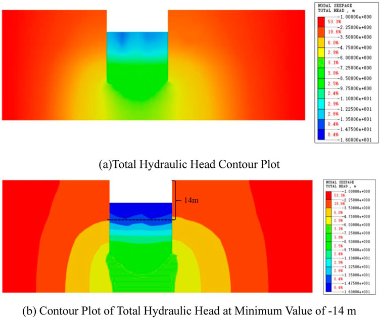
Figure 6. Total hydraulic head at the final dewatering step of the excavation. (a) Total Hydraulic Head Contour Plot (b) Contour Plot of Total Hydraulic Head at Minimum Value of -14 m.
4.2.2 Analysis of disturbance based on pore water pressure
Taking the final dewatering step, from −10 m to −14 m, as an example, the water level in the dewatering wells is maintained 1 m below the expected water level, i.e., at −15 m, after dewatering is completed. The pore water pressure distribution after dewatering is shown in Figure 7. Due to the hydraulic gradient, water from the surrounding soil continuously flows toward the well. As a result, the pore water pressure at the bottom of the well and in the immediate vicinity of the well significantly decreases, with a larger drop in pore water pressure observed in soils closer to the well. In soils further away from the well, the decrease in pore water pressure is relatively smaller. Negative pore water pressure is generated in the soil at the bottom of the excavation near the dewatering well. The area of pore water pressure change caused by the dewatering extends from the excavation surface downward, reaching a depth of approximately 8 m below the excavation surface.

Figure 7. Contour plot of pore water pressure in the soil.
The horizontal displacement of the diaphragm wall is primarily influenced by the lateral pressure exerted by the surrounding soil. During the dewatering process, groundwater outside the excavation flows toward the pit, altering the pore water pressure in the surrounding soil, and thus the seepage action disturbs the external soil. By analyzing the changes in pore water pressure from the dewatering seepage numerical simulation results, the degree of soil disturbance can be assessed. Based on the research of Chen Bouali et al. (2021), Wang et al. (2018), the soil disturbance degree (d) is defined as shown in Equations 1–3. A disturbance degree of d < 0.3 is considered mild disturbance, while d > 0.3 indicates strong disturbance.
where:
The changes in pore water pressure at multiple measurement points located at different depths of the surrounding soil, 3 m, 6 m, and 9 m from the excavation edge, were extracted. The schematic diagram of the measurement points is shown in Figure 8. The disturbance degree
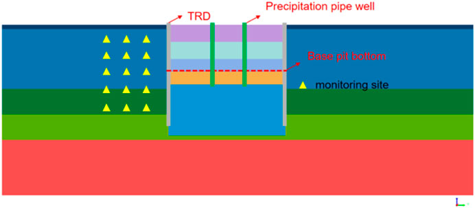
Figure 8. Schematic of pore water pressure measurement points.
The degree of disturbance of the soil outside the excavation is shown in Figure 9. In the horizontal direction, the disturbance caused by the excavation dewatering is generally more significant in soils closer to the pit. In the vertical direction, the disturbance degree in the shallow soil layers (above 6 m) is generally higher, and it decreases with depth as the effects of dewatering diminish. Due to dewatering, free water in the surrounding soil flows toward the excavation, and the closer the soil is to the pit, the smaller the seepage path. This smaller seepage path leads to a higher hydraulic gradient, resulting in greater seepage pressure and, consequently, a larger disturbance to the soil. In the vertical direction, shallow soils, which have a smaller groundwater recharge area, react more quickly to the decrease in groundwater level caused by dewatering, leading to more significant changes in pore water pressure. In contrast, the deeper soils, which have a larger groundwater recharge area and more dispersed flow lines, experience less disturbance from dewatering. At the final dewatering level of −14 m, the disturbance degree curve exhibits a noticeable inflection point. Below this dewatering depth, the disturbance to the soil decreases significantly. With increasing depth, the soil is subject to greater overburden stress, which contributes more significantly to the pore water pressure. Therefore, in deeper soils at the same horizontal location, the disturbance caused by seepage is smaller compared to the shallower soils.
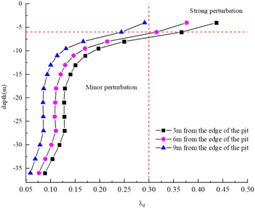
Figure 9. Soil disturbance degree outside the excavation.
4.3 Analysis of soil disturbance induced by excavation on the surrounding soil
4.3.1 Changes in effective stress in the soil surrounding the excavation
To obtain accurate displacement data for the excavation, a displacement reset was set during the geostatic equilibrium phase, assuming that the soil was fully consolidated before excavation. The distribution of effective stress in the surrounding soil at a specific excavation cross-section is shown in Figure 10a. As the depth increases, the self-weight stress of the soil increases, and thus the effective stress in the soil also gradually increases with depth.
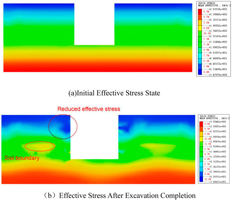
Figure 10. Effective stress in the soil outside the excavation. (a) Initial Effective Stress State (b) Effective Stress After Excavation Completion.
After the completion of excavation, the effective stress in the surrounding soil is shown in Figure 10b. For soils close to the diaphragm wall, excavation induces active earth pressure, leading to a reduction in soil pressure, and consequently, a decrease in effective stress. Along the depth direction, the redistribution of soil pressure causes a sharp change at the soil layer interfaces. The variation in soil properties at these interfaces leads to stress concentration, resulting in an increase in effective stress at the boundaries. At the bottom of the excavation, the reduction in overburden stress due to the excavation of the upper soil layers leads to a decrease in the effective stress in the soil below the excavation surface, which is lower than the initial state.
4.3.2 Disturbance degree analysis based on soil effective stress
The redistribution of soil pressure caused by excavation can affect the self-weight stress of the surrounding soil. Based on the research, which studied the disturbance effects on the soil during the tunnel excavation process in the soft clay region of Shanghai using static cone penetration tests, the soil disturbance degree (SSD) was proposed as shown in Equation 2 (Chen et al., 2011).
where:
In Midas, a calculation parameter SSD (Soil Disturbance Degree) is defined, where parameter [A] represents the effective stress of the soil during the geostatic equilibrium phase, and parameter [B] represents the effective stress of the soil upon completion of the final excavation stage. The disturbance degree is then calculated as the absolute value of the difference, as shown in Equation 3.
The calculation results are shown in Figure 11. In the horizontal plane, the regions with the largest disturbance degree in the soil outside the excavation are located at the junction between the rectangular and arcuate segments of the excavation, particularly on the side of the smaller curvature. Additionally, the soil disturbance degree on the side of the smaller curvature is generally greater than that on the side of the larger curvature. On the side of the excavation with the large-span retaining wall, the soil disturbance is also relatively pronounced. The surface settlement induced by excavation affects the stress state of the surrounding soil, resulting in higher disturbance degrees in areas of greater settlement. The disturbance degree of the surface soil along the 1–1 cross-section of the excavation is shown in Figure 11b. As the distance between the soil and the diaphragm wall increases, the soil disturbance degree first increases and then decreases. Moreover, from the disturbance degree distribution along this section, it is observed that there is a distinctive disturbance degree at the location of the steel supports, which warrants further analysis.
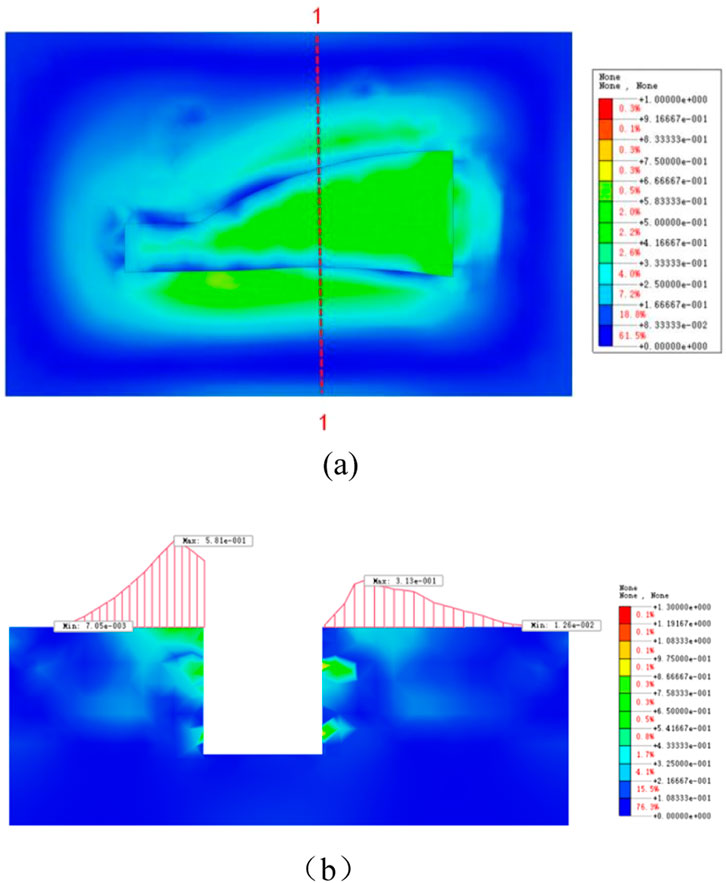
Figure 11. Planar distribution of soil disturbance degree outside the excavation. (a) Planar Distribution of Soil Disturbance Degree. (b) Section disturbance.
Based on the analysis of the calculation results for this cross-section, the portion of the soil with a disturbance degree greater than 0.8 accounts for no more than 1% of the total, so the maximum disturbance degree is adjusted to 0.8 for better clarity. Detailed analysis is focused on the left half of the excavation, as shown in Figure 12. In the vertical direction, at the location of the steel support, the sudden increase in stiffness of the support structure limits the deformation of the external soil toward the excavation, thereby suppressing the development of active earth pressure on the outside. This results in a sharp change in the soil disturbance degree at that depth. The soil disturbance is more pronounced at the bottom of the diaphragm wall, where the soil must withstand significant stress to counteract the “kick-out” effect of the diaphragm wall. At the interface between two soil layers with different properties, the abrupt change in stress state also causes local disturbance in the soil. To comprehensively assess the effect of stress changes caused by irregular excavation on the soil disturbance from a three-dimensional perspective, an equipotential surface of the soil disturbance degree greater than 0.3 is extracted, as shown in Figure 13. A band-shaped disturbed region is observed at the depth range of the steel support and the bottom of the diaphragm wall. Significant disturbance is also found on the external side of the large-span end of the excavation. The soil disturbance around the corners of the excavation and at the junction of the rectangular and arcuate sections of the excavation is weaker. On the other hand, the surface soil around the irregular excavation experiences greater disturbance due to surface settlement, but this disturbance does not extend to deeper soil layers. Overall, the volume of soil with strong disturbance on the smaller curvature side of the excavation is larger than on the larger curvature side.
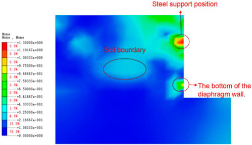
Figure 12. Contour map of soil disturbance outside the excavation.
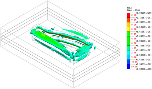
Figure 13. Distribution of soil isosurfaces with disturbance degree greater than 0.3.
5 Analysis of soil disturbance due to excavation-induced leakage
During the excavation process, site inspections revealed localized seepage in certain areas of the excavation is retaining structure, indicating partial failure of the TRD (Tungsten-reinforced diaphragm) waterproofing curtain. The failure of the waterproof curtain can lead to abrupt changes in the seepage field of the external soil, increasing the disturbance of the surrounding soil. This disturbance softens the soil properties locally, which in turn causes an increase in the horizontal displacement of the diaphragm wall in those areas of the excavation.
5.1 Excavation seepage simulation
The excavation retaining structure in this engineering case is geometrically complex. In the numerical simulation, the 3D meshing of the diaphragm wall significantly affects the computation speed. Therefore, a 2D plate element was used to model the diaphragm wall, while impermeable interface elements were employed to simulate the TRD waterproofing curtain. Based on the previous analysis, the disturbance of the surrounding soil is relatively large at the junction between the rectangular section and the small curvature side of the diaphragm wall, and horizontal displacement of the diaphragm wall at this location is also significant. Thus, a failure scenario for the TRD waterproofing curtain was simulated at this location.
To define the leakage points, interface element parameters were assigned, with the permeability coefficient of the interface elements set to that of soft clay. Leakage points were selected at a depth of −9.5 m, both above and below the excavation surface. The attributes of the plate elements at these locations were modified to reflect the leakage point characteristics. Considering the model grid division, the size of the leakage points was set to 0.5 × 0.5 m, as shown in Figure 14.
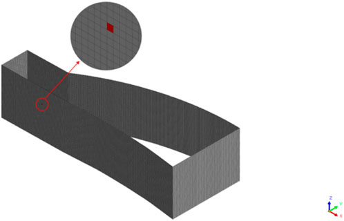
Figure 14. Schematic diagram of leakage point simulation.
To validate whether the simulated TRD failure corresponds with actual site conditions, the total water head distribution of the diaphragm wall at the final dewatering step was extracted. The results, shown in Figure 15, indicate a localized abrupt change in the water head at the specified location of the diaphragm wall, confirming the occurrence of seepage at that point.
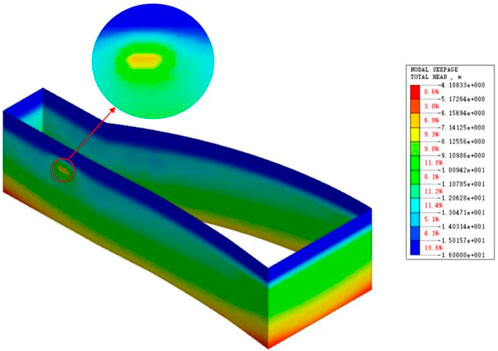
Figure 15. Distribution of total water head in the diaphragm wall.
5.2 Analysis of soil disturbance due to excavation seepage
Seepage through the waterproof curtain can lead to changes in the local seepage field of the surrounding soil. Based on the pore water pressure data extracted from measurement points around the excavation site (as shown in Figure 8 of Section 3), disturbance levels in the surrounding soil are calculated, and the results are presented in Figure 16. When the leakage point is located at −9 m, the disturbance levels in the soil are shown in Figure 16. Significant changes in soil disturbance are observed around the leakage point. For soils located 3 m from the excavation, the disturbance exceeds the threshold for strong disturbance. At a distance of 6 m, the soil disturbance from the leakage is relatively minor, and at 9 m, the soil is almost unaffected by the seepage. As the distance from the excavation increases, the disturbance effect caused by the seepage significantly diminishes.
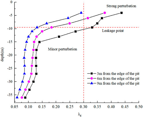
Figure 16. Soil disturbance due to seepage.
Overall, the disturbance to the soil caused by localized seepage is weaker than that resulting from the excavation dewatering process. According to the calculation results, the horizontal displacement of the diaphragm wall at the leakage point increases by only 2% compared to other locations. Therefore, under the assumption of unchanged soil properties in the numerical simulation, the impact of seepage on the horizontal displacement of the diaphragm wall is minimal. In practice, however, localized seepage disturbances can lead to an increase in horizontal displacement of the retaining structure, primarily due to the softening of the soil properties, which in turn causes greater horizontal displacement of the excavation.
5.3 Analysis of excavation-induced deformation based on soil disturbance
To analyze the foundation pit deformationn under disturbed soil conditions, a weakening analysis of the soil layer parameters in disturbed regions is performed based on the different mechanisms of soil disturbance. For the disturbances caused by excavation dewatering and leakage, referring to the study by Deng et al. (2023) on the case of a groundwater inflow accident in a deep excavation, significant changes in the SPT and CPT test results were observed near the failure points after water inflow. According to the test results, in areas with mild disturbance, the M-C parameters of the soil, specifically cohesion (c) and internal friction angle (ψ) were reduced by 2%–19%, while in regions with severe disturbance, the reduction ranged from 28% to 37%. Considering that the groundwater leakage in this case is relatively mild, the soil parameters within a 3-m radius around the leakage point are weakened by 20%. For the disturbance caused by excavation dewatering, the soil parameters within a 6-m range from the edge of the excavation and above a depth of 6 m are weakened by 25%, and the parameters in the deeper layers with minimal disturbance are weakened by 10%.
Regarding the disturbance caused by the stress redistribution during excavation, based on the experimental results by Bai et al. (2023) on the disturbance of soft clay, the stiffness coefficient of disturbed silty clay samples decreased significantly, while the reduction in c and ψ values was relatively small. According to the SSD distribution of effective stress disturbance in the excavation, a 25% weakening of the soil parameters in the disturbed regions is performed. The displacement results of the diaphragm wall after the excavation are then analyzed.
As shown in Figure 17, when only the soil parameters in the seepage zone of the excavation are weakened, the horizontal displacement of the diaphragm wall increases by 9.8% above the excavation surface compared to the initial state, with no significant impact on the location of the maximum displacement of the diaphragm wall. When only the soil parameters in the dewatering disturbance zone are weakened, the overall horizontal displacement of the diaphragm wall increases. Due to the weaker disturbance in the deeper soil layers caused by the dewatering and stronger disturbance in the shallow surface layers, the diaphragm wall maintains a good anchoring effect at depth, resulting in an upward trend in the maximum horizontal displacement. When only the disturbance caused by excavation is considered, the disturbance range is larger compared to the dewatering disturbance, and it also affects the deeper soil layers. As a result, the overall displacement of the diaphragm wall is greater than in the case of dewatering disturbance, and due to the weakening of the deep soil parameters, a “toe” effect occurs at the bottom of the diaphragm wall, with a displacement of 3.7 mm at the base. When considering a single disturbance scenario, the displacement of the diaphragm wall shows a significant deviation from the actual monitoring data. Therefore, a combined analysis of all three disturbance scenarios is conducted.
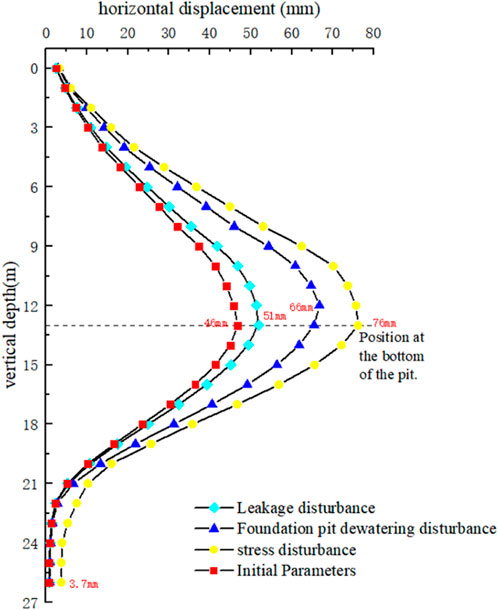
Figure 17. Displacement of the diaphragm wall under different disturbance scenarios.
The combined weakening of soil parameters for three disturbance scenarios was analyzed and compared with monitored data, as shown in Figure 18. For diaphragm wall displacement near the surface, numerical simulation results under the combined weakening scenario closely match the monitored data. However, due to the significant overlap of dewatering and stress disturbances in this region, some areas exhibit simulated displacements exceeding the monitored values. Above the excavation level, the numerical results deviate by approximately 8% from the monitored data, indicating good agreement. Below the excavation level, the simulated diaphragm wall deformation is significantly smaller than the monitored data. Analysis of geotechnical conditions and construction feedback suggests that this discrepancy arises from disturbances caused by the construction of bored piles during retaining structure installation, which weakened the surrounding soil. Additionally, the poor pile quality in weak soil layers led to reduced overall stiffness of the retaining structure, failing to meet the design values and resulting in increased horizontal displacement of the diaphragm wall.
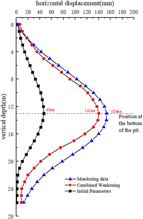
Figure 18. Diaphragm wall displacement: simulation vs monitored data.
6 Conclusion
(1) Numerical simulations of irregular-shaped excavation construction in soft soil areas were conducted using Midas GTS. Compared to rectangular excavations, irregular-shaped excavations exhibit distinctive deformation characteristics. Large deformations are more likely to occur at locations where the cross-sectional shape changes. In contrast,the arching effect of highly curved arc shapes helps reduce the deformation of retaining structures.
(2) Analyses of pore water pressure variations revealed significant disturbance in shallow soils located 3 m outside the foundation pit during dewatering, with a disturbance degree greater than 0.3. Conversely, deep soil layers below the dewatering depth experienced minimal perturbation.
(3) Effective stress analysis indicated that excavation-induced stress redistribution reduced effective stress in soils within 6 m of the pit perimeter, particularly affecting overlying strata and the embedded retaining zone.
(4) Numerical simulations of localized water cutoff curtain failures demonstrated that leakage events caused minor localized soil disturbance confined to the immediate vicinity of breach points.
(5) Combined disturbance (dewatering + excavation + leakage) induced 32%, 45%, and 58% greater displacements compared to individual factors, confirming the critical role of multi-factor coupling effects.
Data availability statement
The original contributions presented in the study are included in the article/supplementary material, further inquiries can be directed to the corresponding author.
Author contributions
XB: Funding acquisition, Investigation, Project administration, Resources, Writing – original draft. ZF: Conceptualization, Data curation, Formal Analysis, Methodology, Project administration, Supervision, Writing – review and editing. JL: Conceptualization, Investigation, Methodology, Supervision, Validation, Writing – original draft. LL: Conceptualization, Data curation, Formal Analysis, Software, Writing – original draft. JY: Formal Analysis, Writing – review and editing.
Funding
The author(s) declare that no financial support was received for the research and/or publication of this article.
Conflict of interest
Authors ZF, JL, and LL were employed by China Design Group Co., Ltd.
The remaining authors declare that the research was conducted in the absence of any commercial or financial relationships that could be construed as a potential conflict of interest.
Generative AI statement
The author(s) declare that no Generative AI was used in the creation of this manuscript.
Publisher’s note
All claims expressed in this article are solely those of the authors and do not necessarily represent those of their affiliated organizations, or those of the publisher, the editors and the reviewers. Any product that may be evaluated in this article, or claim that may be made by its manufacturer, is not guaranteed or endorsed by the publisher.
References
Abbas, Q., Yoon, J., and Lee, J. (2023). Characterization of wall deflection and ground settlement for irregular-shaped excavations with changes in corner configuration. Int. J. Geomechanics 23 (1). doi:10.1061/(asce)gm.1943-5622.0002591
Bai, S.-Y., Wang, W.-J., Xie, X.-Y., and Zhu, D.-L. (2023). Experimental study on HS-small model parameters of soil considering disturbance and its application in foundation pit engineering. Yantu Lixue/Rock Soil Mech. 44 (1), 206–216.
Bouali, M. F., Karkush, M. O., and Bouassida, M. (2021). Impact of wall movements on the location of passive Earth thrust. Open Geosci. 13 (1), 570–581. doi:10.1515/geo-2020-0248
Chen, B., Xu, S., Peng, F., Li, Q., and Ye, W. (2011). Experimental study of indices for evaluating small disturbance in underground-crossing construction. Yanshilixue Yu Gongcheng Xuebao/Chinese J. Rock Mech. Eng. 30 (Suppl. 1), 2682–2689.
Deng, Y. S., Guo, Y. J., Zou, B. P., Wang, J. X., Liu, X. T., Chen, Q. Z., et al. (2023). Failure analysis and zoning control of water gushing in foundation pit. Eng. Fail. Anal. 145, 107029. doi:10.1016/j.engfailanal.2022.107029
Duan, Q., Shi, J., and Wu, D. (2016). Design and realization of foundation pit leakage detection system based on flow-fitting principle. Zhongnan Daxue Xuebao (Ziran Kexue Ban). J. Central South Univ. Sci. Technol. 47 (12), 4108–4114.
Karkush, Mahdi O., and Yassin, S. A. (2020). Using sustainable material in improvement the geotechnical properties of soft clayey soil. J. Eng. Sci. Technol. 15 (4), 2208–2222.
Liu, J.-C., Tan, Y., Song, X.-H., Fan, D.-D., and Liu, T.-R. (2023c). Effects of through-wall leaking during excavation in water-rich sand on lateral wall deflections and surrounding environment. Zhejiang Daxue Xuebao (Gongxue Ban). J. Zhejiang Univ. Eng. Sci. 57 (3), 530–541.
Liu, N. W., Pan, J. J., Li, M. G., and Li, Y. (2023). Deformation characteristics of an ultra-deep and small-scale rectangular excavation in Hangzhou soft clay. Tunn. Undergr. Space Technol. 137, 105117. doi:10.1016/j.tust.2023.105117
Liu, B., Zhang, D. W., Wang, Y. Y., Wang, N. N., and Xu, W. (2023). Design optimization and observed performance of a super-large foundation pit excavation subjected to unsymmetrical loading in water-rich floodplain: a case study. Soils Found. 63 (3), 101329. doi:10.1016/j.sandf.2023.101329
Saba, J., and Mahdi, K. (2023). Shear strength and chemical properties of soft clayey soil treated with magnetized water. Mag. Civ. Eng. 124.8, 12406.
Shi, J. W., Zhong, X. C., Lu, H., Ni, X. D., and Shi, C. (2025). Influence of joint stiffness on three-dimensional deformation mechanisms of pipeline under tunnel active face instability. Canad. Geotech. J. 62, 1–16.
Shi, J. W., Chen, Y. H., Kong, G. Q., Lu, H., Chen, G., and Shi, C. (2024). Deformation mechanisms of an existing pipeline due to progressively passive instability of tunnel face: physical and numerical investigations. Tunne. Under. Spac. Techno. 150, 105822.
Wang, Y. S. Y. (2018). A 3-D conjugated bond-pair-based peridynamic formulation for initiation and propagation of cracks in brittle solids. Int. J. Solids Struct., 134.
Wang, J., Liu, X., Liu, J., Wu, L., Guo, Q., and Yang, Q. (2018). Dewatering of a 32.55 m deep foundation pit in MAMA under leakage risk conditions. KSCE J. Civ. Eng. 22 (8), 2784–2801. doi:10.1007/s12205-017-1950-6
Wu, K. (2022). Application of circular strut system in large special-shaped deep foundation excavations. J. Railw. Eng. Soc. 39 (6), 50–55.
Xu, W., Li, J.-Q., and Duan, C.-J. (2010). Sensitivity analysis of a deep foundation pit with special plane shape to soil parameters. Yantu Gongcheng Xuebao/Chinese J. Geotechnical Eng. 32 (Suppl. 1), 173–176.
Yunteng, , Wang, , Xiaoping, , and Xu, X. (2016). Numerical simulation of propagation and coalescence of flaws in rock materials under compressive loads using the extended non-ordinary state-based peridynamics. Eng. Fract. Mech. 163, 248–273. doi:10.1016/j.engfracmech.2016.06.013
Zhao, Y., Wang, C. L., and Bi, J. (2020). Analysis of fractured rock permeability evolution under unloading conditions by the model of elastoplastic contact between rough surfaces. Rock Mech. Rock Eng. 53, 5795–5808. doi:10.1007/s00603-020-02224-x
Keywords: irregular-shaped excavations, numerical simulation, foundation pit leakage, disturbance of surrounding soils, foundation pit excavation
Citation: Bao X, Fang Z, Lv J, Lu L and Yuan J (2025) Investigation of deformation in irregular excavations and soil disturbance in highly sensitive soft ground regions. Front. Earth Sci. 13:1532635. doi: 10.3389/feart.2025.1532635
Received: 22 November 2024; Accepted: 08 April 2025;
Published: 14 May 2025.
Edited by:
Manoj Khandelwal, Federation University Australia, AustraliaReviewed by:
Mahdi Karkush, University of Baghdad, IraqBalbir Kumar Pandey, Guru Ghasidas Vishwavidyalaya, India
Copyright © 2025 Bao, Fang, Lv, Lu and Yuan. This is an open-access article distributed under the terms of the Creative Commons Attribution License (CC BY). The use, distribution or reproduction in other forums is permitted, provided the original author(s) and the copyright owner(s) are credited and that the original publication in this journal is cited, in accordance with accepted academic practice. No use, distribution or reproduction is permitted which does not comply with these terms.
*Correspondence: JinYang Lv, MTA0MTg0OTg5NEBxcS5jb20=