 Yanjiao Jiang
 Jian Zhou
 Jiaqi Zhang3
- 1School of Earth Sciences, Northeast Petroleum University, Daqing, Heilongjiang, China
- 2State Key Laboratory of Continental Shale Oil, Northeast Petroleum University, Daqing, Heilongjiang, China
- 3School of Physics and Electronic Engineering, Northeast Petroleum University, Daqing, Heilongjiang, China
- 4Daqing Logging and Testing Service Company, PetroChina Co., Ltd., Daqing, Heilongjiang, China
The thin thickness of the sand body and the low oil recovery in the marginal reservoirs of the X area in D oilfield pose significant challenges. Using ultra-short radius horizontal wells is effective for substantially increasing production and designing reasonable well trajectory parameters is crucial for realizing the potential of oil reservoirs. Based on the actual geological system and the rock physical characteristics of the reservoir, and using the theory of oil-water two-phase seepage, a three-dimensional numerical simulation model is established for ultra-short horizontal wells in edge reservoirs to analyze the impact of horizontal well parameters on production. The simulation results show that the production increases with a longer horizontal section length, a greater entry distance, and larger angles between the well and mainstream flow line. The numerical results reveal that the optimal horizontal well length is 200 m, the optimal well orientation is 120°–150° to the main flow line, and the preferred range of entry distance is 50–70 m. For thin layers, horizontal wells located in the middle of the layer are optimal. Based on a coupled analysis of fluid flow in the horizontal wellbore and fluid seepage in the reservoir, a reasonable theoretical length of the horizontal well section is determined, and its reliability is verified with examples. The theoretical analysis is consistent with the simulation results. This study elucidates the influence of drilling trajectory parameters on thin-layer oil marginal reservoirs, and the determination of optimal parameters improves the scientific basis of trajectory design. These findings provide an important reference for residual oil dredging strategies.
1 Introduction
Petrophysicist and Bechtel of the United States proposed ultrashort radius horizontal well technology in the early 1980s (Dickinson et al., 1992; Huang et al., 2023; Tang, 2013). This technology can directly drill through an oil and gas reservoir by opening a window in the original well casing to build a deviation expands the drainage area of reservoirs, and greatly improves well production and crude oil recovery (Dickinson et al., 1989; Osama et al., 2023; Toma and Reitman, 1991). This type of well is the main technical means for exploiting the remaining oil in thin oil layers, marginal oil fields, and dead oil areas. In recent years, the sidetracking horizontal well technology has been widely used and developed (Husein et al., 2022; Osama et al., 2023; Zakirov et al., 2023). Existing research methods for optimizing the trajectory of sidetracked horizontal wells are diverse, and they provide trajectory parameters such as horizontal well length and entry distance. For example, the geological model-based method optimizes trajectory design by analyzing reservoir characteristics or dynamic drilling data (Huang et al., 2023; Kim et al., 2024; Saikia, 2013; Toma and Reitman, 1991; Zhang et al., 2019). While this method can adapt to complex geological conditions, it relies on high-quality geological data (Khodanovich et al., 2021; Mahmood and Guo, 2021; Osama et al., 2023; Wang et al., 2022). Meanwhile, the mathematical model-based method describes wellbore trajectories using optimization algorithms to determine the optimal trajectory, allowing for the flexible adjustment of objectives and constraints (Ren et al., 2021; Samuel and Liu, 2009; Yue et al., 2018). However, it struggles with highly nonlinear and complex constraint problems (Wang et al., 2016; Wang et al., 2018). The intelligent algorithm-based method (Huang et al., 2021; Orodu et al., 2011) is suitable for multi-objective, nonlinear, and complex constraint optimization problems, but it requires a large amount of data for training and validation (Biswas et al., 2021; Huang et al., 2022). Research has shown that the precise control of wellbore trajectories is challenging in thin reservoirs and complex structures. Since the X area of the D oilfield has entered the high water-cut development stage, the boundary reservoirs have a certain amount of remaining oil reserves (Huang et al., 2023; Orodu et al., 2011; Tang, 2013). Determining how to effectively exploit the remaining oil in the marginal and thin reservoirs of old wells has thus become an urgent problem that needs to be solved in the current development stage.
The design of a scientifically optimized ultra-short sidetrack trajectory, along with precise target positioning, is particularly crucial for enhancing the recovery rate of hydrocarbons (Lei et al., 2022; Tang, 2013). This study focuses on tapping the production potential of old wells in marginal reservoirs. The research targets a stratum that has been exploited for 10 years, where the production interval has encountered water breakthrough, leading to a declining recovery factor. Based on the trajectory control characteristics of sidetracked horizontal wells and considering thin-layer conditions and reservoir rock physical characteristics, this study establishes a three-dimensional geological model for optimizing the trajectory design of sidetracked horizontal wells. By using the reservoir numerical simulation method, the influences of the angle, length, interval, and other factors on the productivity of sidetracking horizontal wells are simulated to determine the optimal trajectory parameters for sidetracking horizontal wells. The numerical simulation model truly reflects the law of trajectory control of ultra-short sidetracking horizontal wells and can effectively improve the scientific nature of the trajectory design of horizontal wells. Additionally, by considering friction loss in the horizontal wellbore as well as applying the coupling theory of horizontal wellbore fluid flow and reservoir fluid seepage, a method for determining the optimal length of the horizontal section is introduced. The rationality and reliability of the method are verified with example measurements.
The scarcity of data from old wells and the limited marginal scope make it challenging to apply intelligent algorithms and geosteering methods in the target area. However, the geological model simulation approach effectively adapts to the complexities encountered during the late development phase of marginal reservoirs, closely aligning with actual production conditions. The numerical model is designed with high precision and strong applicability, allowing for dynamic parameter adjustments based on production outcomes. This research aims to achieve an optimal sidetrack trajectory design through mathematical analysis and numerical simulation, thereby facilitating the maximum control over the remaining oil reserves in the marginal reservoirs of old wells.
2 Theory and method
2.1 Numerical simulation
2.1.1 Seepage mechanism
In this research, when establishing the dynamic seepage model in the study area, simplified assumptions are made for the reservoir and fluid. The basic assumptions for the adopted reservoir numerical simulation method are as follows: 1) The seepage in the reservoir is isothermal. 2) There are two phases of oil and water in the reservoir, and the percolation of each phase follows Darcy’s law. 3) Oil and water are not miscible. 4) The thickness of the oil layer is uniform. 5) Formation rocks and fluids can be compressed. 6) The influences of gravity and capillary pressure are considered (Jiang et al., 2021; Khodanovich et al., 2021; Won et al., 2008).
The initialization of the oil-water two-phase model refers to the initial distribution of unknown quantities, such as the oil and water phase pressure and saturation in the reservoir. The equilibrium method is used for initialization (Jiang, et al., 2017a). The depth of the given reference point, the pressure corresponding to the reference depth, the depth of the oil-water interface, and the capillary pressure at the oil-water interface, as well as the pressure, saturation, and other distributions of the reservoir in the initial state, can be calculated, thus completing the initialization of the oil-water two-phase model. The process of reservoir production is simulated using the pressure difference between the wellbore and the formation (Jiang, et al., 2017a; Jiang, et al., 2017b). The reservoir in the target area is part of an oilfield developed by water injection. Considering the production data of oil and water wells in the area over the years, the reservoir distribution after 10 years of production of old wells is set as the initial production time for the sidetracking horizontal wells through numerical simulation pretreatment. The data for the flow pressure and static pressure over the years are selected to be the reference basis for fitting the pressure and flow pressure of the formation. Therefore, we can acquire the data record of formation pressure and fluid saturation during the production process based on the numerical simulation.
2.1.2 Formation model
The characteristics of reservoirs in the study area are taken as the standard. The core analysis data, well-testing geological data, and other elevant data are used. Based on the theory of oil-water two-phase percolation flow, a formation model is established based on the actual formation system and the basic petrophysical characteristics of the reservoir. The basic parameter settings for the numerical simulation model are shown in Table 1, and they consider the formation conditions, rock physical properties, high temperature and high-pressure physical property test data for the reservoir, and permeability isotropy.

Table 1. Numerical simulation data for the formation model of sidetracked horizontal well.
The formation model adopts the Cartesian coordinate system for the three-dimensional block centre grid. The reservoir area is divided into a box grid, with 100, 100, and 10 grid cells in the x, y, and z directions, respectively. The relative locations of the water injection wells according to the actual well location data for the oilfield are shown in Figure 1A. The initial fluid distribution of the horizontal well simulation is shown in Figure 1B. The process of fluid flow and production in the formation are simulated while accounting for the pressure difference between the formation pressure and the bottom-hole flow pressure (Jiang et al., 2021; Wang and Jiang, 2003). Sensitivity analysis of the factors affecting the productivity of sidetracking horizontal wells is then carried out.
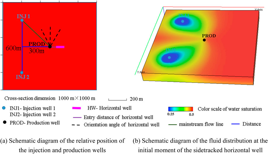
Figure 1. Schematic diagram of numerical simulation formation model for sidetracked horizontal wells. (a) Schematic diagram of the relative position of the injection and production wells. (b) Schematic diagram of the fluid distribution at the initial moment of the sidetracked horizontal well.
Based on the theoretical framework of two-phase fluid flow (Wang and Jiang, 2003), and considering the applicable conditions and simulation parameters of the formation model, the finite difference method is used to solve the seepage equation and the convection-diffusion equation for formation water salinity (Jiang, et al., 2017a). This method can discretize continuous problems, and it is one of the most widely used and well-developed methods in numerical simulation. When the finite difference method is used to solve the seepage equation, the region to be solved is divided into finite difference grids and used to replace the continuous solution domain (Deng et al., 2010). The flow variables to be solved are stored on each grid point, and the corresponding difference quotient is used to replace the differential term in the partial differential equation. In other words, the partial differential equations are converted into algebraic difference equations, and the difference equations containing finite unknown variables at discrete points are obtained (Wu et al., 2004; Jiang, et al., 2017a). By solving the difference equations, the numerical solutions for flow variables at the grid points can be obtained.
2.2 Optimization theory of horizontal section length
2.2.1 Fluid flow in horizontal wellbore
Based on the volume balance between the reservoir flow and the wellbore flow, the relationship between the flow variation at any position along the horizontal section of the horizontal well and the reservoir flow to the well is obtained as follows (Chen et al., 2003):
where x represents the coordinates along the horizontal wellbore direction (in m), qw(x) is the total production above position x in the horizontal section (in m3/d), and qs(x) is the wellbore flow rate per unit length of the horizontal well section (in m3/(d·m)). A minus sign (“−”) indicates that the fluid flow occurs in the negative direction of the x-axis.
For horizontal wells in reservoirs with an outer boundary, Equations 2, 3 are the two boundary conditions:
where Pw(x) is the pressure at coordinate x along the horizontal wellbore direction (in Mpa), Pe is the external boundary pressure of the oil reservoir (in Mpa), and Pwf is the flow pressure in the horizontal section (in Mpa).
2.2.2 Coupled theory
The characteristics of the design of ultra-short radius horizontal wells and the impact of various factors on the production capacity of the well section are accounted for. It is assumed that the horizontal well is located in a reservoir with impermeable top and bottom boundaries, the length of the horizontal well section is L, and the fluid seepage in the reservoir satisfies Darcy’s law. The coupling of the reservoir fluid seepage and wellbore fluid flow is shown in Figure 2.
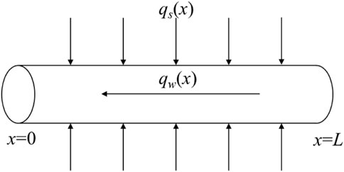
Figure 2. Schematic diagram of reservoir fluid seepage coupled with wellbore fluid flow.
Crude oil usually enters the wellbore of a horizontal well through good connectivity with the reservoir, thereby facilitating extraction. Due to the presence of friction losses in the horizontal section, pressure drop inhomogeneity occurs in the direction along the horizontal section. When the pressure drop in the reservoir and the pressure drop in the horizontal section are equal, the pressure drop at the end of the horizontal section is very small or zero, and the production capacity of the well decreases. Assuming that the fluid in the oil reservoir has turbulent flow, the flow equation (Chen et al., 2003) for a horizontal well in a horizontal section is given by
where Js is the oil production index of the horizontal well section (in m3/Mpa), and Pwf (x) is the flow pressure at a certain position x in the horizontal section (in Mpa).
The oil recovery index equation for a horizontal well per unit length is given by Equation 5
where K is the formation permeability (in mD), β is the anisotropy ratio of permeability,
The flow characteristics of fluids in a horizontal wellbore can be described by Equation 6:
where the resistance to flow in a horizontal wellbore is
From the principle of volume conservation of fluid in the wellbore and fluid in the reservoir, the relationship between the flow rate changes at any position in the horizontal section of a horizontal well and the fluid flow in the reservoir is derived in Equation 1 (Jia et al., 2018).
The derivation of Equation 4 is obtained as follows:
Assuming that Js is constant, substituting Equation 7 into Equation 1 and differentiating the result yields Equation 8
Both sides are multiplied by
where, Q is the production with pressure drop in the horizontal wellbore (in m3/d), and qw is the well rate at an arbitrary position along the horizontal well (in m3/d).
The boundary conditions of Equation 7 are used to obtain the following expression:
Substituting Equation 10 into Equation 9 yields
2.2.3 Determination of the optimal length
Integrating Equation 11 according to the boundary conditions
where L is the length of the horizontal well (m).
Equation 12 is the relationship between the well production and the length of the horizontal well section when considering the pressure drop in the horizontal wellbore. When the pressure drop is neglected,
where
The above equation indicates that a longer horizontal well section is not necessarily better. When designing a horizontal well section, it is necessary to achieve a balance between length and friction loss. The principle (Ben, 1990) for determining the reasonable length of horizontal segments can be expressed as Equation 14:
The value corresponding to the above equation is the optimal length of the horizontal well.
Then, Equation 12 can be transformed into a relationship between horizontal wells at a different horizontal section locations x and production at different locations, as Equation 15:
where
3 Results
3.1 Numerical simulation results
The impacts of the sidetracked horizontal well parameters on well productivity are determined, including the horizontal well angle, horizontal well length, interval distance, and horizontal well position. This section describes the numerical simulation research conducted on the trajectory parameters of sidetracking horizontal wells to provide a reference for the optimal trajectory design of sidetracking horizontal wells.
3.1.1 Horizontal well angle
To simulate the impact of the horizontal well and mainstream angle on the production capacity, the changes in the daily production and cumulative production of production wells are simulated when the horizontal well and mainstream angle are 30°, 60°, 90°, 120°, and 135°. The other basic simulation conditions for a horizontal well are as follows: the entry distance is 50 m, the horizontal well length is 100 m, and the well is located in the middle of the oil layer. Figure 3 shows the numerical simulation results of daily production and cumulative production at different angles between the horizontal wells and mainstream lines. From the simulation results, it can be seen that as the angle between the horizontal well and the mainstream line increases, the daily and cumulative oil production gradually increases. When the angle increases to 120°, the production increase is not significant. Figure 4 shows the fluid distribution in the middle of the oil layer at different angles over a production time of 10 years. It can be seen that the oil saturation near the horizontal well varies significantly depending on the angle of the horizontal well relative to the main streamline. When the angle is 30°, after a period of production, part of the horizontal well comes into contact with injected water, reducing the oil saturation to about 0.25, which severely affects the oil production. As the angle of the horizontal well increases, the oil saturation around the well also rises, leading to improved oil production. When the angle reaches 135°, the fluid near the horizontal well approaches the original reservoir oil saturation, and the simulated production values also indicate that the oil production is highest at this angle. The numerical simulation results show that the production is higher at angles between 120° and 150°, with the optimal production occurring at a mainstream angle of 135°.
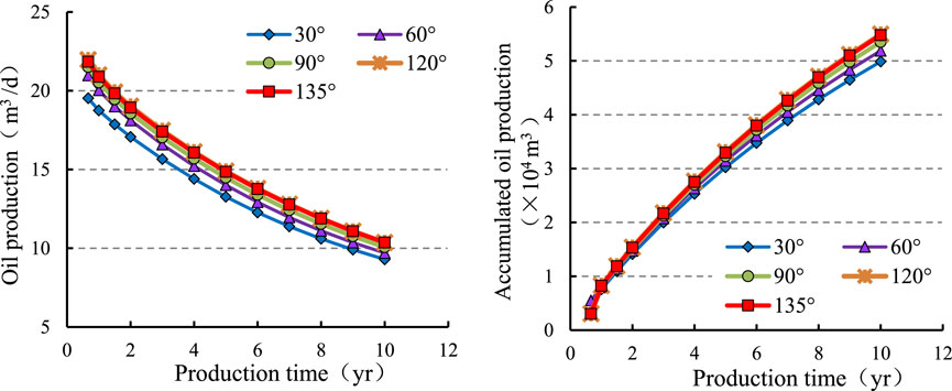
Figure 3. Plot of different horizontal well angles to the mainstream line versus production.
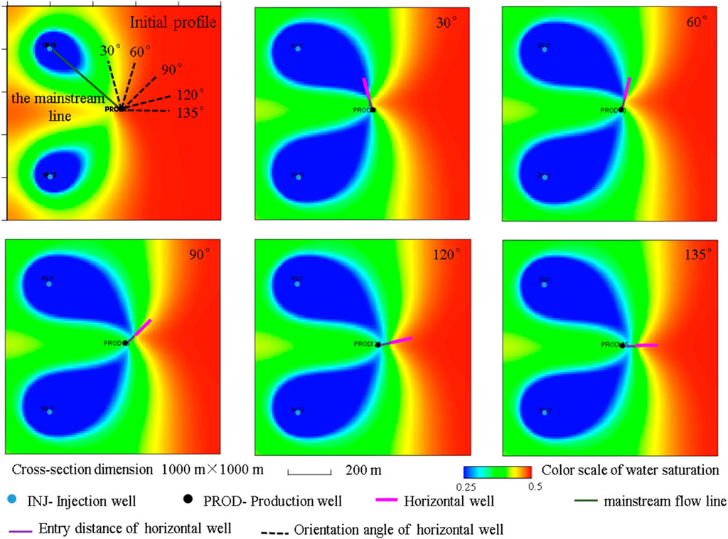
Figure 4. Fluid distribution in the middle of the formation for different horizontal well angles to the mainstream line. (production time = 10 years).
3.1.2 Horizontal well length
To determine the effect of the horizontal well length on the production capacity, the variations in the daily and cumulative production of producing wells are simulated for horizontal well lengths of 50, 80, 100, 150, 200, and 250 m. The other basic simulation conditions of the model are as follows: the entry distance is 50 m, the angle between the horizontal well and the mainstream line is 135°, and the well is located in the middle of the oil formation. Figure 5 shows the numerical simulation results for the daily and cumulative production at different horizontal well lengths. Figure 6 shows the fluid distribution in the middle of the oil formation with different horizontal well lengths when the production time is 10 years. When the entry distance is constant, horizontal wells of different lengths exhibit significant differences in saturation around the well after the same production period. When the horizontal well is 50 m long, although the oil saturation around the well remains relatively high, its limited length restricts its production capacity, resulting in lower output. As the length of the horizontal well increases, its production capacity also rises, while the oil saturation around the well decreases rapidly, leading to higher production.From the simulation results, it can be seen that with an increase in the horizontal well length, the daily and cumulative oil production increases gradually. When the length increases to 200 m, the horizontal well length continues to increase, the increment of the daily and cumulative oil production is not significant, and the result is optimal when the horizontal well length is 200 m.
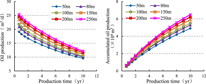
Figure 5. Plot of different horizontal well lengths versus production.
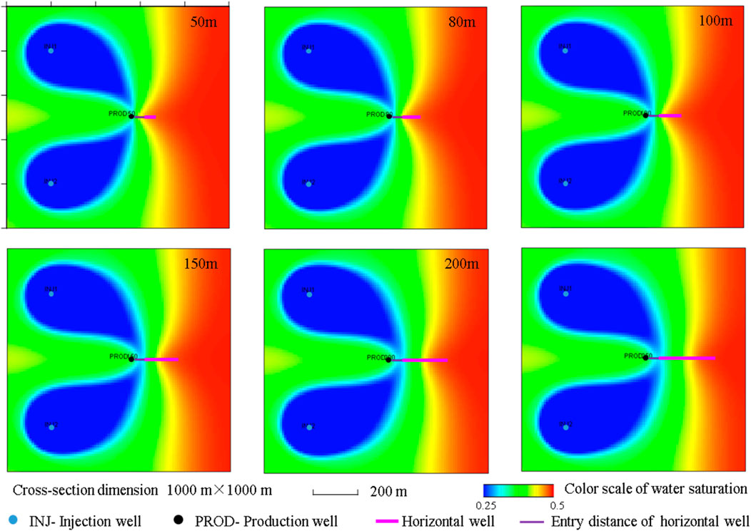
Figure 6. Fluid distribution in the middle of the formation for different horizontal well lengths (production time = 10 years).
3.1.3 Entry distance
To determine the effect of the entry distance on the production, the changes in the daily and cumulative production of the producing wells are simulated when the lengths of the entry distance are 30, 40, 50, 60, 70, 80, 90, and 100 m. The other basic simulation conditions of the model are as follows: the horizontal well length is 100 m, the angle between the horizontal well and the mainstream line is 135°, and the well is located in the middle of the oil formation. Figure 7 shows the numerical simulation results for the daily and cumulative production with different entry distance lengths, and Figure 8 shows the fluid distribution in the middle of the oil formation with different entry distance conditions when the production time is 10 years. When the horizontal well length is constant and the entry distance varies, the oil saturation around the horizontal well, particularly on the side closest to the production well, changes significantly during the same production period. When the entry distance is 30 m, the oil saturation near the production well side is approximately 0.3. As the entry distance increases, the oil saturation on this side gradually rises to 0.4, which leads to an increase in the production. From the simulation results, it can be seen that the daily and cumulative oil production gradually increases with the increase in the length of the entry distance. With an increase in the length of the entry distance, the increment of the daily and cumulative oil production is relatively stable. Considering the factors of frictional resistance in the horizontal well sections and engineering costs, the optimal range of the entry distance can be 50–70 m.
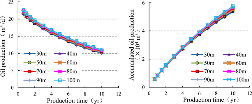
Figure 7. Plot of different entry distances versus oil production.
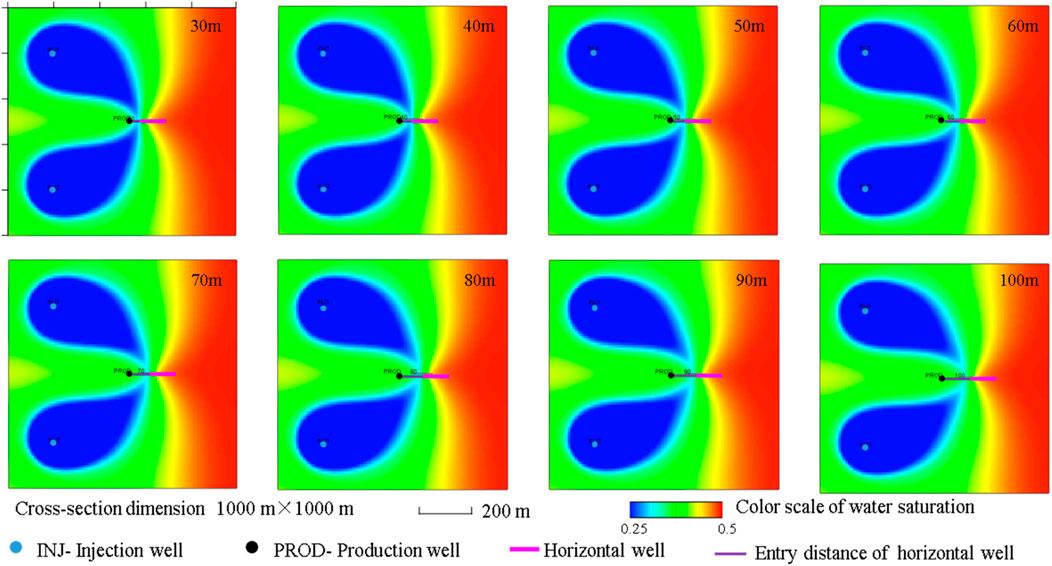
Figure 8. Fluid distribution in the middle of the formation for different entry distances (production time = 10 years).
3.1.4 Horizontal well position
To obtain the effect of horizontal well location on production, the changes in the daily and cumulative production of producing wells are simulated when the horizontal well is located in the upper part of the formation (1.5 m from the top) and in the middle part of the formation and the lower part of the formation (1.5 m from the bottom). The other basic simulation conditions of the model are as follows: the entry distance is 50 m, the horizontal well is 100 m, and the angle between the horizontal well and the mainstream line is 135°. Figure 9 shows the numerical simulation results for the daily and cumulative production of different horizontal well positions, while Figure 10 shows the fluid distribution in the middle of the formation under different horizontal well position conditions after 10 years of production. The position of the horizontal well within the layers has little effect on the distribution of oil saturation around the well. The simulation results show no notable changes in daily production and cumulative daily production. Considering the simulation values and the factors involved in thin-layer drilling operations, positioning the horizontal well at the centre of the layer is optimal.
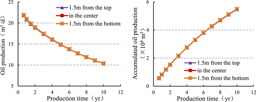
Figure 9. Plot of different horizontal well positions versus oil production.
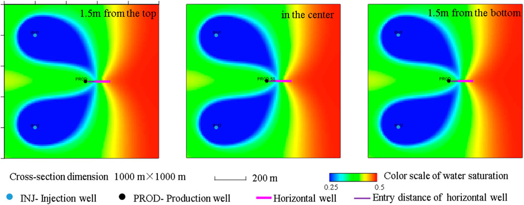
Figure 10. Fluid distribution in the middle of the formation for different horizontal well positions (production time = 10 years).
3.2 Optimization length example
The parameters of the Dx well instance are as follows: rw = 0.1098 m, K = 36.4 mD, β = 2.25 Zw = 3 m, Bo = 1.06, μo = 24 mPa·s,
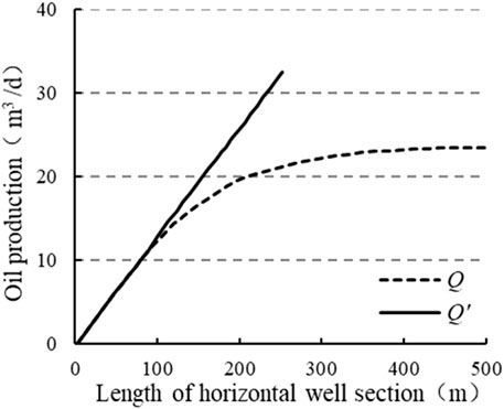
Figure 11. Relationship between horizontal well production and horizontal well section length.
4 Discussion
The correct design for the reasonable position of a sidetracking horizontal well and a reasonable length for the horizontal section are two key issues in the design of the marginal reservoir development plan. For the design of the horizontal well angle, entry distance, and position in thin oil layers, within a reasonable numerical range, the geological characteristics of the reservoir should also be considered. The geological structural conditions, the lithology within the layer, and the determination of the remaining oil enrichment areas also need to be incorporated (Dong et al., 2020; Zhou et al., 2022; Zhou et al., 2023).
Regarding the issue of horizontal well length, as the length of a horizontal section increases, the production capacity of a horizontal well often increases. This is because a greater reservoir area can be exposed to the production pipeline, thereby increasing the oil flow rate and achieving higher productivity. However, with an the increase in the well length, the impact of frictional losses within the horizontal wellbore on production becomes significant and cannot be ignored. Friction gradually accumulates and has an increasing impact on the production at the bottom of the well. In long horizontal wells, frictional losses significantly increase the total energy consumption of the fluid, which further weakens the increase in productivity caused by wellhead pressure reduction. Previous numerical simulations and productivity theory studies have shown that simply increasing the length of a horizontal section cannot significantly improve the productivity of horizontal wells. When assuming an infinitely long horizontal section, there is a theoretical limit in the production of a horizontal well (Chen et al., 2003). This conclusion is also supported by Figure 11. In this study, the optimal length of a sidetracked horizontal well in complex reservoir models is determined through numerical simulation and theoretical analysis, thereby improving prediction accuracy. The paper examines the trajectory of sidetracked horizontal wells from the perspectives of geology and development, analyzing the relationship between well trajectory and the distribution of remaining oil while targeting the remaining oil with relatively low water content. The optimal horizontal well angle and appropriate entry distance into the layer are then determined. Based on static reservoir descriptions, using numerical simulation as a tool, and guided by theoretical analysis, this study explores new approaches for tapping into the potential of remaining oil reserves.
An increase in the length of the designed horizontal section will lead to an increase in drilling and completion costs. Therefore, while adjusting and analyzing the technology used to develop thin-layer marginal reservoirs, the impact of marginal benefits on cost must be considered. The optimal well trajectory parameters identified in this study require more detailed geological and engineering research to formulate effective strategies to enhance production (Y. Huang et al., 2023). Numerical simulation models can accurately describe the seepage mechanisms of reservoirs without relying on complex optimization algorithms (Ren et al., 2021; Yue et al., 2018). Compared to geological guidance technology (Mahmood and Guo, 2021), this method offers lower equipment costs and simpler data processing. However, currently popular machine learning methods often yield optimization results with poor interpretability (Biswas et al., 2021; Huang et al., 2022). The main difficulty of the numerical simulation method in this study lies in the fact that the establishment of the stratigraphic model must conform to the geological characteristics of the target reservoir, which requires extensive data such as regional geology, core samples, and production data. The advantage of this method is that it enables virtual development, allowing for more flexible design tailored to formation characteristics. On the basis of this study, further research should focus on the distribution of remaining reserves and the selection of favorable areas to derive optimal development strategy, which will provide new opportunities for effectively improving the effectiveness of oilfield development.
5 Conclusion
Based on the theory of oil-water two-phase seepage, this study carries out an investigation of the trajectory parameters of side-drilled horizontal wells in marginal reservoirs, leading to the following conclusions.
(1) The numerical simulation results show that production increases with the horizontal section length, entry distance, and the angles between the well and mainstream flow line. Comparing numerical results, the optimal horizontal well length is 200 m. The angle between the horizontal well and the main stream line is 120°–150°, the production is best when the angle of the main stream is 135°, and the preferred range of the layer entry distance is 50–70 m. It is optimal for the horizontal well to be located in the middle of the oil formation.
(2) Based on the coupling theory of fluid flow in the horizontal wellbore and fluid seepage in reservoirs, a method for determining the optimal horizontal section length is derived. Considering friction loss in the horizontal wellbore, the relationship between production and horizontal well length deviates from a linear increase. When the length exceeds a certain threshold, the incremental increase in production gradually declines. The theoretical analysis of the example well aligns with numerical simulation results, confirming the rationality and reliability of the method.
(3) By analyzing the trajectory factors affecting the production capacity of side-drilled horizontal wells, the laws governing the influence of the well parameters is obtained, and the optimal parameter range is determined. This model has characteristics of precise design and strong applicability to geological formations. To maximize oil production, parameters can be adjusted according to the characteristics of different reservoirs. The research results can serve as a basis for selecting optimal lateral drilling well locations.
Data availability statement
The original contributions presented in the study are included in the article/Supplementary Material, further inquiries can be directed to the corresponding author.
Author contributions
YJ: Writing – original draft, Writing – review and editing. JnZ: Formal Analysis, Writing – review and editing. JqZ: Investigation, Writing – review and editing. ZG: Methodology, Writing – review and editing. DL: Software, Writing – review and editing. XL: Formal Analysis, Writing – review and editing. JG: Project administration, Writing – review and editing.
Funding
The author(s) declare that financial support was received for the research and/or publication of this article. This work was supported in part by the Natural Science Foundation of Heilongjiang Province, China (Grant Number LH2023D011).
Acknowledgments
The authors thank the reviewers and editors for their valuable comments, which helped improve the manuscript.
Conflict of interest
Author DL was employed by PetroChina Co Ltd.
The remaining authors declare that the research was conducted in the absence of any commercial or financial relationships that could be construed as a potential conflict of interest.
Generative AI statement
The authors declare that no Generative AI was used in the creation of this manuscript.
Publisher’s note
All claims expressed in this article are solely those of the authors and do not necessarily represent those of their affiliated organizations, or those of the publisher, the editors and the reviewers. Any product that may be evaluated in this article, or claim that may be made by its manufacturer, is not guaranteed or endorsed by the publisher.
References
Ben, J. D. (1990). Pressure drop in horizontal wells and its effect on production performance. J. Petroleum Technol. 42 (11), 1426–1433. doi:10.2118/19824-PA
Biswas, K., Vasant, P. M., Gamez Vintaned, J. A., and Watada, J. (2021). Cellular automata-based multi-objective hybrid grey wolf optimization and particle swarm optimization algorithm for wellbore trajectory optimization. J. Nat. Gas Sci. Eng. 85, 103695. doi:10.1016/j.jngse.2020.103695
Chen, H., Li, X., and Li, Q. (2003). Study of the determining method of optimal length of horizontal well. J. Southwest Petroleum Inst. 25 (1), 47–49.
Deng, S., Li, Z., Fan, Y., and Chen, H. (2010). Numerical simulation of mud invasion and array laterolog response in deviated wells. Chin. J. Geophys. 53 (4), 994–1000. doi:10.3969/j.issn.0001-5733.2010.04.024
Dickinson, W., Anderson, R. R., and Dickinson, R. W. (1989). The ultrashort-radius radial system. Spe Drill. Eng. 4 (3), 247–254. doi:10.2118/14804-pa
Dickinson, W., Dykstra, H., Nees, J. M., and Dickinson, E. (1992). Ultrashort radius radial system applied to thermal recovery of heavy oil. SPE West. Reg. Meet., 53–70. doi:10.2118/24087-ms
Dong, X., Shen, L. W., Liu, X., Zhang, P., Sun, Y., Yan, W., et al. (2020). NMR characterization of a tight sand’s pore structures and fluid mobility: an experimental investigation for CO2 EOR potential. Mar. Petroleum Geol. 118 (January), 104460. doi:10.1016/j.marpetgeo.2020.104460
Huang, W., Hu, J., Lu, C., and Min, W. (2022). Experiment and result analysis of multi-object intelligent optimization algorithm for 3D sidetracking trajectory. Drill. Eng. 49 (4), 23–30.
Huang, W., Wu, M., Chen, L., Chen, X., and Cao, W. (2021). Multi-objective drilling trajectory optimization using decomposition method with minimum fuzzy entropy-based comprehensive evaluation. Appl. Soft Comput. 107, 107392. doi:10.1016/j.asoc.2021.107392
Huang, Y., Liu, H., and Liu, Z. (2023). “The development and application of ultra-short radius lateral drilling technology in low-permeable reservoir of Western South China Sea,” in Proceedings of the SPE/IADC Middle East Drilling Technology Conference and Exhibition, 2023-May.
Husein, N., Malyavko, E., Gazizov, R., Bydzan, A., Kapranov, G., and Gorbokonenko, O. (2022). “The dynamic marker-based production profile surveillance in horizontal and multilateral wells at the North Caspian offshore fields society of Petroleum engineers,” in SPE annual caspian technical conference 2022, November 15–17, 2022, Nur-Sultan, Kazakhstan. doi:10.2118/212059-MS
Jia, X., Lei, G., and Sun, Z. (2018). Review of horizontal well productivity water breakthrough in edge-aquifer oil reservoir with different drainage patterns. Tezhong Youqicang = Special Oil and Gas Reservoirs. 1–7. doi:10.3969/j.issn.1006-6535.2018.05.001
Jiang, Y., Sun, J., Gao, J., and Cui, J. (2017a). Mud invasion and array laterolog responses in horizontal well based on numerical simulation. J. Geophys. Eng. 14 (1), 15–25. doi:10.1088/1742-2132/14/1/15
Jiang, Y., Sun, J., Gao, J., Zhang, P., and Cui, J. (2017b). A simulation of mud invasion and characteristics of array laterolog responses in a low-permeability gas reservoir: a case study. J. Geophys. Eng. 14 (3), 456–465. doi:10.1088/1742-2140/aa5e69
Jiang, Y., Zhou, J., Fu, X., Cui, L., Fang, C., and Cui, J. (2021). Analyzing the origin of low resistivity in gas-bearing tight sandstone reservoir. Geofluids 2021, 1–15. doi:10.1155/2021/4341804
Khodanovich, D. A., Grachev, S. I., and Sokhoshko, S. K. (2021). Sidetrack and horizontal wells trajectories planning on the complex reservoirs based on hydrodynamic models analysis. Neft. Khozyaystvo - Oil Ind. 2021 (9), 56–59. doi:10.24887/0028-2448-2021-9-56-59
Kim, Y., Akagbosu, P., Ndokwu, C., and Adesokan, I. (2024). “Three-phase saturation evaluation utilizing multidetector pulsed neutron logging in freshwater environments: a guide for sidetrack drilling optimization,” in Society of Petroleum Engineers - SPE Nigeria Annual International Conference and Exhibition, NAIC 2024, Lagos, (NG), 5 August 2024.
Lei, Q., Xu, Y., Cai, B., Guan, B., Wang, X., Bi, G., et al. (2022). Progress and prospects of horizontal well fracturing technology for shale oil and gas reservoirs. Petroleum Explor. Dev. 49 (1), 191–199. doi:10.1016/S1876-3804(22)60015-6
Mahmood, M. N., and Guo, B. (2021). Productivity comparison of radial lateral wells and horizontal snake wells applied to marine gas hydrate reservoir development. Petroleum 7 (4), 407–413. doi:10.1016/j.petlm.2021.10.004
Orodu, O. D., Tang, Z., and Anawe, P. A. L. (2011). Sidetrack and recompletion risk evaluation - waterflooded reservoir. J. Petroleum Sci. Eng. 78 (3–4), 705–718. doi:10.1016/j.petrol.2011.08.015
Osama, M., Sumaida, A. S. B., El Shahat, A., Al Mutawa, A., Almazrouei, S., Saleh, A., et al. (2023). “Case study of multilaterals drilling in under-balanced coiled tubing drilling (UBCTD) implementation and challenges for the first time in operator group of companies,” in ADIPEC 2023, Abu Dhabi, UAE, October 2–5, 2023. United States: Society of Petroleum Engineers. doi:10.2118/216202-MS
Ren, J., Gao, Y., Fang, N., and Wang, D. (2021). Pressure behavior of multi-stage fractured horizontal well in a laterally non-uniform reservoir. J. Petroleum Sci. Eng. 207 (May), 109054. doi:10.1016/j.petrol.2021.109054
Saikia, K. (2013). Real-Time modeling-while-drilling for optimized geosteering and enhanced horizontal well placement in thin and complex reservoirs. Soc. Petroleum Eng. - Int. Petroleum Technol. Conf. 2013, IPTC 2013 Challenging Technol. Econ. Limits Meet Glob. Energy Demand 3, 2313–2320. doi:10.2523/iptc-16715-ms
Samuel, R., and Liu, X. (2009). Wellbore tortuosity, torsion, drilling indices, and energy: what do they have to do with well path design? Proc. - SPE Annu. Tech. Conf. Exhib. 5, 2831–2844. doi:10.2118/124710-ms
Tang, M. (2013). “Design and application of expandable casing technology of deep sidetrack horizontal well in the oilfield,” in International Petroleum Technology Conference, Beijing, China, March 26–28, 2013. 2716–2723. doi:10.2523/iptc-16760-abstract
Toma, P., and Reitman, V. (1991). Long and ultrashort turning radius ofHorizontal wells: predictions of futureProduction based on today’s experience. 13th World Petroleum Congr. WPC-24148.
Wang, J., and Jiang, R. (2003). Physical simulation of oil reservoir for enhancing oil recovery by sidetracking horizontal wells. doi:10.3969/j.issn.1674-7259.2003.03.014
Wang, X. H., Zhang, F. S., Yin, Z. R., Weng, D. W., Liang, H. B., Zhou, J. P., et al. (2022). Numerical investigation of refracturing with/without temporarily plugging diverters in tight reservoirs. Petroleum Sci. 19 (5), 2210–2226. doi:10.1016/j.petsci.2022.05.006
Wang, Z., Gao, D., and Liu, J. (2016). Multi-objective sidetracking horizontal well trajectory optimization in cluster wells based on DS algorithm. J. Petroleum Sci. Eng. 147 (May), 771–778. doi:10.1016/j.petrol.2016.09.046
Wang, Z., Gao, D., Liu, J., Hu, D., and Wu, W. (2018). “What is the optimal trajectory of sidetrack horizontal well for bypassing obstacles in cluster wells?,” in Society of Petroleum Engineers - SPE Kingdom of Saudi Arabia Annual Technical Symposium and Exhibition 2018, SATS 2018, Dammam, (SA), April 23–26, 2018.
Won, S., Bilgesu, H. I., and Ameri, S. (2008). Investigation of mud-filtrate invasion using computational fluid dynamics. doi:10.2118/117769-MS
Wu, J., Torres-Verdín, C., Sepehrnoori, K., and Delshad, M. (2004). Numerical simulation of mud-filtrate invasion in deviated wells. SPE Reserv. Eval. Eng. 7 (2), 143–154. doi:10.2118/87919-PA
Yue, Q., Liu, J., Zhang, L., and Zhang, Q. (2018). The posting-buckling analysis and evaluations of limit drilling length for coiled tubing in the sidetrack horizontal well. J. Petroleum Sci. Eng. 164 (September 2017), 559–570. doi:10.1016/j.petrol.2018.01.061
Zakirov, Z., Galiev, R., Miftahov, R., Galimova, N., and Karimov, T. (2023). “Improving reservoir efficiency by drilling super slim multilateral wellbores,” in ADIPEC 2023, Abu Dhabi, UAE, October 2–5, 2023. United States: Society of Petroleum Engineers, 1–12. doi:10.2118/216443-MS
Zhang, J., Wang, G., He, K., and Ye, C. (2019). Practice and understanding of sidetracking horizontal drilling in old wells in Sulige Gas Field, NW China. Petroleum Explor. Dev. 46 (2), 384–392. doi:10.1016/S1876-3804(19)60018-2
Zhou, J., Liu, B., Shao, M., Song, Y., Ostadhassan, M., Yin, C., et al. (2023). Pore structure analysis and classification of pyroclastic reservoirs in the Dehui fault depression based on experimental and well-logging data. Geoenergy Sci. Eng. 224 (February), 211620. doi:10.1016/j.geoen.2023.211620
Zhou, J., Liu, B., Shao, M., Yin, C., Jiang, Y., and Song, Y. (2022). Lithologic classification of pyroclastic rocks: a case study for the third member of the Huoshiling Formation, Dehui fault depression, Songliao Basin, NE China. J. Petroleum Sci. Eng. 214 (March), 110456. doi:10.1016/j.petrol.2022.110456
Keywords: marginal reservoir, ultra-short sidetrack horizontal well, numerical simulation, well location optimization, productivity evaluation
Citation: Jiang Y, Zhou J, Zhang J, Guo Z, Liu D, Li X and Gao J (2025) Trajectory optimization of ultra-short sidetrack horizontal wells in marginal reservoirs. Front. Earth Sci. 13:1533309. doi: 10.3389/feart.2025.1533309
Received: 23 November 2024; Accepted: 25 March 2025;
Published: 11 April 2025.
Edited by:
Jianmeng Sun, China University of Petroleum (Huadong), ChinaReviewed by:
Gang Bi, Xi’an Shiyou University, ChinaDahlia A. AL-Obaidi, University of Baghdad, Iraq
Copyright © 2025 Jiang, Zhou, Zhang, Guo, Liu, Li and Gao. This is an open-access article distributed under the terms of the Creative Commons Attribution License (CC BY). The use, distribution or reproduction in other forums is permitted, provided the original author(s) and the copyright owner(s) are credited and that the original publication in this journal is cited, in accordance with accepted academic practice. No use, distribution or reproduction is permitted which does not comply with these terms.
*Correspondence: Yanjiao Jiang, anlqaWFvMDIyNEAxNjMuY29t