 Xuewei Tong1
 Wenjia Ma
- 1River and Lake Protection Center of the Ministry of Water Resources, Beijing, China
- 2College of Geosciences and Engineering, North China University of Water Resources and Electric Power, Zhengzhou, China
- 3Henan Haihe River Basin Water Conservancy Affairs Center, Xinxiang, China
- 4Henan Province Water Conservancy Second Engineering Bureau Group Co., Zhengzhou, China
Currently, challenges such as water gushing, rock bursts, and large deformations persist during diversion tunnel excavation, necessitating the study of surrounding rock stability post-excavation. This paper focuses on the No.1 tunnel of the Xiaolangdi North Bank Irrigation Area project. The settlement of the surface and vault was monitored on site, and a three-dimensional tunnel model was established by FLAC 3D to analyze the displacement evolution law of the key monitoring sections of the surface and vault. Finally, the formula of time effect between surface and vault settlement of tunnel 1# is deduced and verified. Results show: (1) Settlements increase sharply early on, slow later, and stabilize, with arch roof settlement exceeding surface settlement; (2) The arch settlement is generally 2-3 times greater than the surface settlement, both following similar trends in FLAC 3D simulations; (3) The monitoring data were slightly smaller than the simulation data, with the arch roof settlement error ranging from 0.09 mm to 0.72 mm, and surface settlement errors from 0.5 to 3.71 mm; (4) The error rate between the results obtained from the deduced formula and the actual monitoring is between 0.62% and 9.39%, with a surface settlement warning threshold of 10 mm to ensure safe excavation. Discrepancies between simulations and field data likely stem from idealized model assumptions versus real-world geological heterogeneity. The spatio-temporal correlation model can provide quantitative reference for monitoring scheme optimization and disaster warning of similar projects.
1 Introduction
In recent years, China has made major breakthroughs and progress in tunnel engineering, but the tunnel excavation process faces complex engineering geological conditions. The instability of tunnel surrounding rock may lead to surface subsidence, collapse and other problems, which has a significant impact on the safety and durability of the tunnel. Therefore, it is very important to study the stability of surrounding rock after tunnel excavation (Song et al., 2023; Yu et al., 2023).
In the process of tunnel excavation, in order to ensure the stability of the tunnel structure after excavation, the surface settlement and vault settlement of the tunnel are usually monitored on site. (Lai et al., 2023; Lai et al., 2015; Zhang, 2022; Xie et al., 2020). Wang et al. (2020) established the safety grade and judgment basis of steel arch stability on the basis of monitoring the stress of inner and outer flanges of steel arch. Chen et al. (2017) conducted a comprehensive study and analysis of on-site monitoring results and surrounding rock stability; MacPherson et al. (2006) evaluated the stress-strain law through on-site monitoring; Chen et al. (2022a) analyzed and compared the field monitoring data, and simulated and monitored the whole process of foundation pit excavation. However, due to the influence of geological conditions and complex terrain in the cave, in areas where monitoring tests are difficult to carry out, numerical simulation methods are often used to analyze (Liu et al., 2023; Huang et al., 2020; Zhu et al., 2024; Lin et al., 2012). Chen et al. (2022b) conducted a model test on the surrounding rock and lining structure of the tunnel to simulate the whole process of tunnel construction. Ren et al. (2019) simulated and reproduced the whole process of tunnel construction by conducting model experiments on surrounding rock and lining structure based on the typical deep buried section of Xianglushan Tunnel. Gao and Jing (2023) comprehensively obtained the temporal and spatial evolution law of TBM tunnel deformation by analyzing the influence of composite stratum and its supporting form on the stability of tunnel surrounding rock. Zhang et al. (2020) used the Peck formula to determine the width coefficient of the sedimentation tank and the loss rate of the sand mixed stratum, and analyzed the settlement law of the vertical and horizontal surface and vault by establishing a three-dimensional numerical model of the tunnel. Li et al. (2012) introduced a new analysis method-stochastic technique (SMT) combined with genetic programming (GP) in the prediction of ground subsidence due to tunneling in mountainous areas. The methodology involves the use of stochastic medium theory to generate theory models and to predict ground subsidence due to tunneling in mountainous areas. Zhou et al. (2022) used numerical simulation method to simulate the construction process by three methods: “double-hole interval column method”, “fan-shaped reaming method” and “gate climbing method”. The stress and displacement of the surrounding rock-supporting system and the distribution of the plastic zone of the surrounding rock caused by the three methods are analyzed, and the construction scheme of the transfer section is determined. Wang et al. (2023) analyzed the mechanism of the surface settlement in double-track tunnels in shallow buried loess area. Then establish a surface settlement prediction formula suitable for symmetric and asymmetric double-track tunnels in shallow buried loess area, determine the parameters of increment and position of the maximum on surface settlement offset the net distance ratio. Hu et al. (2023) proposed an improved IPSO-BP algorithm with adaptive inertia weight and particle mutation factor, and combined with the traditional BP neural network, the horizontal and vertical surface settlement data of the corresponding monitoring points were compared and predicted. Based on the mirror image theory and Mindlin solution, Deng et al. (2022) derived the surface subsidence prediction formula, and established a finite difference model based on the example of Changsha power tunnel project. The law of ground surface settlement caused by shield tunneling along the curve section is analyzed. Feng et al. (2022) used analytical method, numerical simulation and field measurement method to compare the law of land subsidence caused by shield excavation of small radius curved tunnel. However, the existing research mainly focuses on spatial deformation modes, such as the distribution and law of surface subsidence, while the time evolution law of the correlation between vault and surface subsidence has not been systematically quantified.
In this paper, the 1 # tunnel of the main canal of the north bank irrigation area of Xiaolangdi is taken as the engineering background. Through on-site monitoring research and numerical simulation analysis, the surface settlement monitoring value and the vault settlement monitoring value are fitted and analyzed. The time effect formula between the two is verified by regression analysis, and the evolution law of surface settlement value with vault settlement value in time factor is obtained. The established spatio-temporal correlation model can provide a quantitative reference for the optimization of monitoring schemes and disaster warning of similar projects. It can detect potential risks in time, reduce the probability of sudden landslides and other disasters, and ensure the safe operation of the project. It has broad application prospects for monitoring and risk assessment of similar underground engineering, tunnel construction and water conservancy infrastructure.
2 Engineering situation
The 1 # tunnel pile number ZG22 + 445-ZG22 + 500 section of the main canal 1 # tunnel of the irrigation area project on the north bank of the wave bottom is located in Jiyuan City, Henan Province. The length of the line is about 100 m. The inlet elevation of the study section is 228.12 m, the outlet elevation is 229.75 m, and the groundwater level is 2.8 m higher than the floor. The engineering area is covered with loess layer, and the lower layer is interbedded with argillaceous calcareous cemented sandstone and mudstone. The rock layer tends to be northeast, and the dip angle is about 23–30°. The surrounding rock is mostly mudstone and argillaceous sandstone. The joints are well developed and the integrity is poor. The surrounding rock grade is V grade. The tunnel site geological conditions is shown in Figure 1.
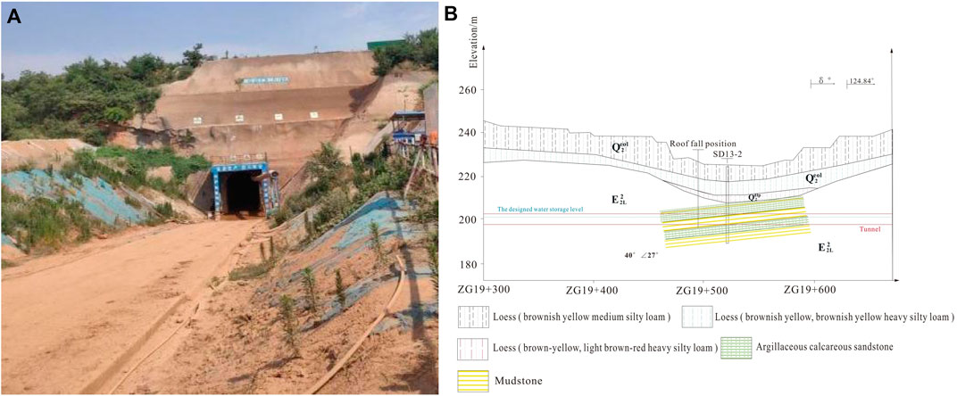
Figure 1. Tunnel site geological conditions; (A) Tunnel exit illustration; (B) Strata distribution diagram.
The excavation section of the diversion tunnel in the tunnel site is a circular arch straight wall type. The buried depth of the tunnel is about 20 m, and the diameter of the tunnel is 2.16 m. The tunnel lining structure is sprayed C25 concrete, B20 @ 1000, L = 2 m system anchor, A6@200 steel mesh, national standard I14 I-steel arch, C20 reinforced concrete full-section lining, and the steel arch spacing is 1 m. The tunnel support is shown in Figure 2. The steel arch is set with B20 connecting steel bars in the circumferential direction, and one bar is set every 1 m, a total of 13 bars; two B20, L = 2 m locking anchors were set at the bottom foot and the arch, with 8 anchors in each piece. The transverse joint width of the supporting lining structure is 20 mm, and the rubber water stop belt, foam board and polysulfide sealant are set in the joint.
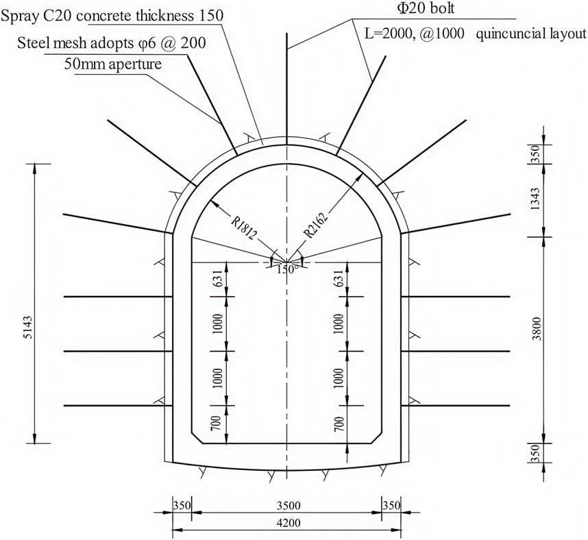
Figure 2. Schematic diagram of tunnel body support for the main canal 1 # of the Xiaolangdi North Bank Irrigation Area Project.
During the construction of 1 # tunnel, a serious soil collapse occurred near the tunnel face, and the amount of collapse was about 500 m3. The main source was the loess between the top arch of the tunnel face and the surrounding rock on both sides, and between the arch and the original sprayed soil. The collapse caused a large-scale subsidence on the ground at the top of the tunnel. The diameter of the collapse pit was about 30 m, and the surface at the collapse pit was about 20 m away from the tunnel vault. The ground collapse on site was shown in Figure 3.
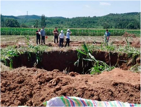
Figure 3. Site ground collapse diagram.
3 Settlement rule analysis
3.1 Monitoring scheme
In order to ensure the safe construction, the surface settlement and vault settlement were monitored during the construction of the 1 # tunnel of the main canal in the north bank of Xiaolangdi irrigation area. Ten monitoring points were evenly arranged, with a total length of 150 m and a target interval of 5 m. From near to far, they were target 1–10 respectively. This paper mainly analyzes the data obtained from the monitoring of target 1–5, and the specific layout is shown in Figure 4.
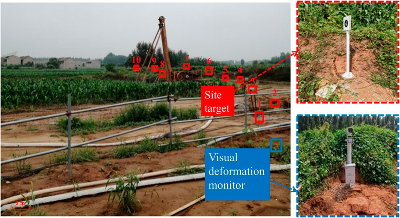
Figure 4. Location of Target.
In order to clearly describe the change process of surrounding rock deformation with space during tunnel excavation, the time history curve of vault settlement deformation obtained from field monitoring is processed. Considering that the actual tunnel construction speed is about 1 meter per day, the abscissa of the curve is set to the excavation mileage (that is, the distance after the monitoring section), while the ordinate still indicates the settlement value.
3.2 Analysis of ground settlement
As shown in Figure 5, when the monitoring curve of target 1 is excavated through the monitoring section of 0–10 m, the settlement deformation rate is significant, and the cumulative settlement value increases rapidly to 3.88 mm. Subsequently, when the excavation passes through the monitoring section of 10–35 m, the settlement deformation rate begins to decrease gradually, and the settlement value is about 7.45 mm. When the distance between the excavation and the monitoring section exceeds 35 m, the surface settlement deformation curve tends to be stable, and finally stabilizes at about 9.23 mm. When the monitoring curve of target 2 passes through the monitoring section of 0–10 m, the cumulative settlement value increases rapidly to 4.97 mm. Subsequently, when the excavation passes through the monitoring section of 10–35 m, the settlement value is about 11.75 mm. When the distance of excavation through the monitoring section is more than 35 m, the final stability is about 13.59 mm. When the monitoring curve of target 3 passes through the monitoring section of 0–10 m, the cumulative settlement value increases rapidly to 6.83 mm. Subsequently, when the excavation passes through the monitoring section of 10–35 m, the settlement value is about 10.87 mm. When the distance of excavation through the monitoring section is more than 35 m, the final stability is about 12.54 mm. By analyzing the monitoring curve of target 4, it can be found that when the excavation passes through the monitoring section of 0–10 m, the settlement value increases rapidly to 6.77 mm; subsequently, when the excavation passes through the monitoring section of 10–35 m, the settlement value is about 11.47 mm. When the distance of excavation through the monitoring section is more than 35 m, the final stability is about 12.63 mm. By analyzing the monitoring curve of target 5, it can be found that when the excavation passes through the monitoring section of 0–10 m, the settlement value increases rapidly to 7.12 mm; when the excavation passes through the monitoring section of 10–35 m, the settlement value is about 12.47 mm. When the distance of excavation through the monitoring section is more than 35 m, the final stability is about 12.63 mm.
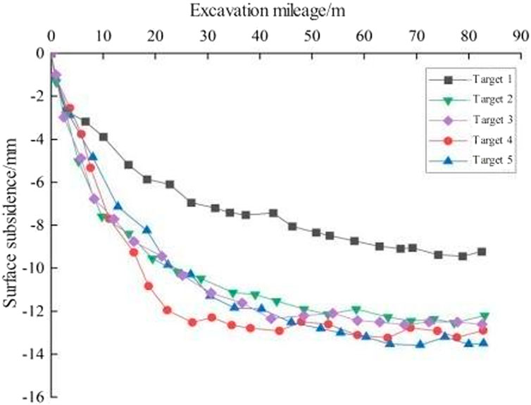
Figure 5. Surface subsidence variation curves of each monitoring section.
3.3 Analysis of vault settlement
As shown in Figure 6, when the monitoring curve of target 1 is excavated through the monitoring section of 0–10 m, the settlement deformation rate is significant, and the cumulative settlement value increases rapidly to 12.35 mm. When the excavation passes through the monitoring section of 10–35 m, the settlement deformation rate begins to decrease gradually, and the settlement value is about 23.34 mm. When the distance between the excavation and the monitoring section exceeds 35 m, the surface settlement deformation curve tends to be stable, and finally stabilizes at about 25.24 mm. When the monitoring curve of target 2 passes through the monitoring section of 0–10 m, the settlement value increases rapidly to 13.27 mm. When the excavation passes through the monitoring section of 10–35 m, the settlement value is about 23.86 mm. When the distance of excavation through the monitoring section is more than 35 m, it is stable at about 25.71 mm. When the monitoring curve of target 3 passes through the monitoring section 0–10 m, the settlement value increases rapidly to 13.21 mm. When the excavation passes through the monitoring section of 10–35 m, the settlement value is about 23.91 mm. When the distance of excavation through the monitoring section is more than 35 m, it is stable at about 25.73 mm. When the monitoring curve of target 4 passes through the monitoring section of 0–10 m, the settlement value increases rapidly to 11.24 mm. When the excavation passes through the monitoring section of 10–35 m, the settlement value is about 23.84 mm. When the distance of excavation through the monitoring section is more than 35 m, it is stable at about 25.49 mm. When the monitoring curve of target 5 passes through the monitoring section of 0–10 m, the settlement value increases rapidly to 15.19 mm. When the excavation passes through the monitoring section of 10–35 m, the settlement value is about 24.75 mm. When the distance of excavation through the monitoring section is more than 35 m, it is stable at about 25.66 mm.
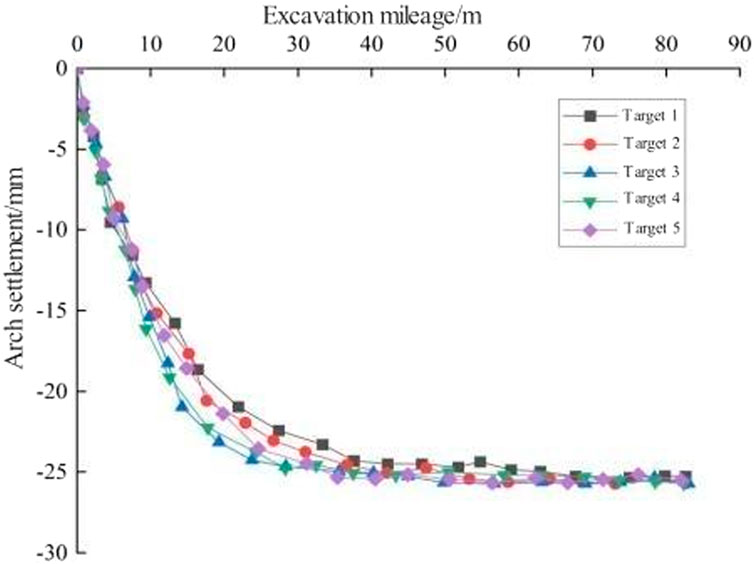
Figure 6. Curve of settlement variation of arch crown at each monitoring section.
Comparing the characteristics of surface subsidence changes in the above five monitoring sections, it can be shown that the spatial changes of surface subsidence deformation follow three similar stages: rapid growth stage, slow growth stage, and stable stage. This phenomenon is mainly due to the structural characteristics of the surrounding rock of the tunnel section, that is, the upper loess lower argillaceous sandstone. Comparing the surface and vault settlement curves of the tunnel, the vault settlement value is greater than the surface settlement during the whole excavation process. The difference between the vault settlement and the surface settlement in the early stage gradually increases with the excavation. Finally, with the stability of the two, the difference tends to be stable. The final settlement differences of the five monitoring sections are 16.01 mm, 12.12 mm, 13.19 mm, 12.86 mm, and 12.42 mm, respectively.
4 Finite element simulation verification
4.1 Computation module
Numerical simulation software FLAC 3D is used for numerical calculation. Referring to the design parameters and geological conditions of the actual tunnel section, the model parameters are set as follows: the excavation diameter is 2.16 m, the buried depth of the tunnel top is 20 m, the distance between the tunnel top and the bottom boundary of the model is 30 m, and the distance between the left and right boundaries of the model is 25 m. The excavation direction is set to 130 m, and the overall size is 50 m × 50 m × 130 m (X × Z × Y). The boundary conditions used in this simulation are: the upper boundary of the model is taken to the ground without limiting the displacement; to protect; the tunnel is in the center of the model, which reduces the influence of boundary conditions. The boundary conditions at the bottom of the tunnel are often simplified into fixed displacement boundaries, which limit the displacement of the bottom boundary in all directions and constrain the displacement value of the bottom boundary to zero. The established bolt model is set as Cable element, the steel arch model is set as Beam element, and the tunnel wall is set as a Shell element to simplify the replacement lining structure, steel mesh and concrete spray layer. The three-dimensional finite element model of the tunnel and the supporting structure are shown in Figure 7. The whole section excavation is adopted in the calculation process, and each excavation is supported by 1 m. The Null model is given to the excavation area to simulate the excavation process. After 130 cycles of excavation, in order to observe the displacement of the monitoring section after excavation and to avoid the influence of boundary effect, the sections of y = 40 m, y = 45 m, y = 50 m, y = 55 m and y = 60 m are taken as the monitoring sections, corresponding to the actual monitoring section target 1, target 2, target 3, target 4 and target 5. The monitoring points are set on the surface and the top of the cave, and the monitoring section is shown in Figure 8. The calculation parameters of each formation are set as shown in Table 1.
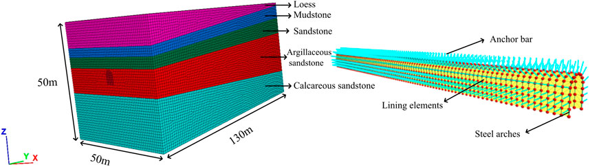
Figure 7. Three-dimensional finite element model of tunnel and supporting structure diagram.
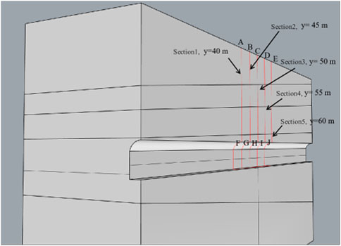
Figure 8. Schematic diagram of monitoring section layout.
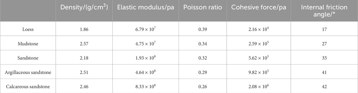
Table 1. Schematic diagram of the three-dimensional finite element model of the tunnel.
4.2 Simulation result analysis
Figure 9 shows the displacement cloud diagram of surrounding rock in Z direction after the excavation of 1# tunnel in the north bank irrigation area of Xiaolangdi. When Y = 40 m, 45 m, 50 m, 55 m and 60 m, the maximum displacement of the vault settlement is 2.55 cm, 2.58 cm, 2.583 cm, 2.591 cm and 2.596 cm, respectively. Even if the location of the monitoring section is different, the maximum difference between the maximum displacement and settlement of each point is only 1.81%. When Y = 40 m, 45 m, 50 m, 55 m and 60 m, the maximum displacement of the ground surface settlement is 9.73 mm, 9.87 mm, 9.94 mm, 1.02 cm and 1.08 cm, respectively. Even if the location of the monitoring section is different, the maximum difference between the maximum displacement and settlement of each point is 11.1%.
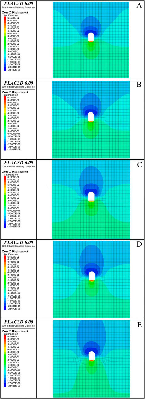
Figure 9. Z-direction displacement cloud map of monitoring section. (A) Y = 40 m section. (B) Y = 45 m section. (C) Y = 40 m section. (D) Y = 55 m section. (E) Y = 60 m section.
4.3 Monitoring and simulation comparison
The maximum settlement values of the vault and the surface after the final stabilization of each section are collected, as shown in Table 2. It is concluded that the settlement value measured by the actual monitoring is slightly smaller than the settlement value obtained by the numerical simulation. With the increase of excavation depth, it shows an increasing trend, and the settlement value of the vault is generally 2–3 times the surface settlement value.
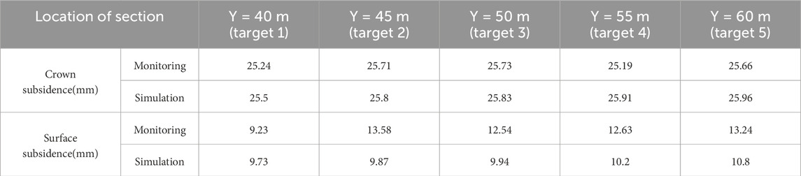
Table 2. Simulation and monitoring vertical displacement table for each monitoring section.
5 Time effect of surface and vault settlement
In engineering practice, conventional tunnel monitoring can effectively obtain surrounding rock deformation data. However, under complex geological conditions (such as broken surrounding rock, shallow buried section or high-risk collapse area), the layout of monitoring points in the tunnel is often limited by construction safety and timeliness, resulting in incomplete or lagging data acquisition. The existing empirical formulas, such as Peck method (PECK, 1969) and mirror method (SAGASETA, 1987), can effectively predict the surface settlement after tunnel excavation.
5.1 Time effect formula derivation
Since the actual excavation footage of the 1 # tunnel of the main canal is 1 m/d, the daily collection of on-site monitoring data can be approximately equal to the collection of 1 m excavation, so the relationship between settlement and excavation footage is approximately equal to the relationship between settlement and time. Based on the on-site monitoring data, the effect relationship between vault settlement and time can be regarded as x2 ∼ t, and the effect relationship between surface settlement and time can be regarded as x1 ∼ t. It is assumed that the difference between vault settlement and surface settlement is X, and the expression is shown in Equation 1. Because the actual monitoring data default to the downward settlement value as a negative value, in order to facilitate the calculation, the settlement value is subtracted after the absolute value is processed. Through the statistics and analysis of the monitoring curve of the difference between the vault and the surface settlement of each section and the time, the regression analysis is carried out, and the X ∼ t curve of each section is obtained, as shown in Figure 10.
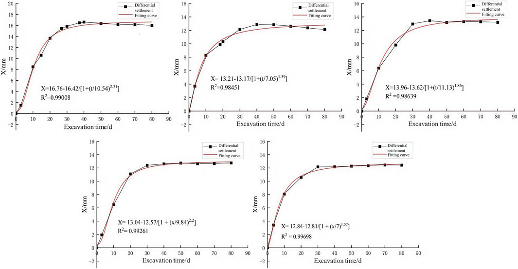
Figure 10. Schematic diagram of time effect regression analysis of settlement difference of each target monitoring section.
By analyzing the error, it is concluded that the error between the vault settlement value calculated by the regression analysis formula and the vault settlement value obtained by the actual monitoring is between 0.002 mm and 0.095 mm. The regression analysis formula is feasible. And the time effect law between the surface settlement and the vault settlement of the five monitoring sections is single. Therefore, the regression analysis formula derived in Figure 11 is used to integrate the data of the five monitoring sections, and the formula suitable for the whole process of tunnel excavation is derived.
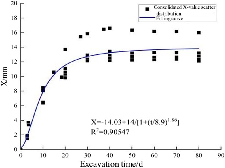
Figure 11. Schematic diagram of regression analysis on the relationship between integrated settlement difference and time.
Through the regression analysis of the scatter points in Figure 11, the relationship between the surface settlement and the vault settlement of the monitoring section with time is obtained, and the specific formula is Formula 2.
Because X is set as the settlement difference between the surface and the vault, the formula of the relative relationship between the surface settlement and the vault settlement with time can be obtained by substituting Formula 1 into Formula 2, as shown in Formula 3.
In the formula, x2 is the settlement value of the vault at time t; x1 is the settlement value of the surface at time t. a1 = 14.03; a2 = 14; a3 = 8.9; a4 = 1.86.
5.2 Time effect formula verification
By comparing the settlement value obtained by the fitting formula with the actual monitoring settlement value, the overall average error is 0.449 mm. The error rate is calculated by the error rate formula, as shown in Equation 4 (Burden and Faires, 2010).
In the formula, W is the error rate; x2 is the fitting vault settlement; x2* is the actual monitoring vault settlement. The maximum error is 2.37 mm, but the total settlement of the section during this period is 25.24 mm, and the error rate is 9.39%. The minimum error is 0.16 mm. The total settlement of the section during this period is 25.66 mm, and the error rate is 0.62%. In general, the fitting formula can accurately predict the relationship between the settlement value of the surface and vault of the tunnel at different positions and time.
5.3 The time effect formula is verified by the whole tunnel
Through the analysis and research of the monitoring data, the time effect formula between the surface settlement and the vault settlement of the fixed monitoring section is deduced. However, in the actual excavation process, the fixed section cannot be studied only. Therefore, through further derivation, the section displacement relationship after excavation is analyzed.
After the excavation passes through the A0 section and continues to be excavated to the position shown in Figure 12, the vault settlement and surface settlement values of the A1 section are analyzed. It is assumed that △S is excavated after passing A0. The time △t experienced after the excavation of the A1 section is shown in Formula 5. The surface monitoring values x1 ∼ A1 of the A1 section are substituted into Formula 3 to obtain the vault displacement settlement value at this time, as shown in Formula 6.
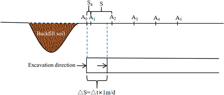
Figure 12. Schematic diagram of the relationship between A1 section settlement and excavation.
After the excavation passes through the A0 section and continues to be excavated to the position shown in Figure 13, the vault settlement and surface settlement values of the A3 section are analyzed. It is assumed that △S is excavated after passing A0, and the time △t experienced after the excavation of the A3 section is shown in Formula 7. The surface monitoring values x1 ∼ A3 of the A3 section are substituted into Formula 3 to obtain the vault displacement settlement value at this time, as shown in Formula 8.
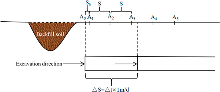
Figure 13. Schematic diagram of the relationship between A3 section settlement and excavation.
After the excavation passes through the A0 section and continues to be excavated to the position shown in Figure 14, the vault settlement and surface settlement values of the A5 section are analyzed. It is assumed that △S is excavated after passing A0, and the time △t experienced after the excavation of the A5 section is shown in Formula 9. By substituting the surface monitoring values x1 ∼ A5 of the A5 section into Formula 3, the vault displacement settlement value at this time can be obtained, as shown in Formula 10.
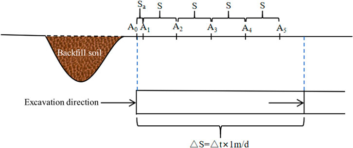
Figure 14. Schematic diagram of the relationship between A5 section settlement and excavation.
According to the relevant national standards, the allowable value of surface settlement of diversion tunnel with gate type of V surrounding rock should be controlled within 10 mm. Therefore, the early warning value of surface settlement x1 is set to 10 mm, and the early warning is carried out once the surface settlement exceeds the value, as shown in Formula 11.
6 Conclusion
In this paper, the time effect between surface settlement and vault settlement during tunnel construction is studied by means of field monitoring, FLAC 3D numerical simulation and theoretical derivation for the No.1 diversion tunnel project in the north bank irrigation area of Xiaolangdi. The main conclusions are as follows:
(1) After the tunnel excavation, the surface settlement and vault settlement of each section show a trend of rapid growth in the early stage, slow settlement rate and stable settlement, and both of them gradually tend to be stable after the excavation to the section of 35 m. The stable values of surface subsidence in the five monitoring sections are 9.23 mm, 13.59 mm, 12.54 mm, 12.63 mm and 13.24 mm respectively. The stable values of vault settlement are 25.24 mm, 25.71 mm, 25.73 mm, 25.49 mm and 25.66 mm respectively. As the excavation progresses, the difference gradually increases and then tends to be stable. The reason is that the excavation of the tunnel leads to the emergence of a cavity, and the settlement of the vault causes the surface settlement. Because the settlement rate of the vault is greater than the surface settlement, the settlement difference shows a trend of increasing gradually. However, with the excavation to the monitoring section after 35 m, the surface settlement and the vault settlement value tend to be stable, and the settlement difference tends to be stable.
(2) The tunnel vault settlement and surface settlement simulated by FLAC 3D show similar laws. After tunnel excavation, the vault settlement value is generally 2–3 times of the surface settlement value. The monitoring data is slightly smaller than the simulation data. The vault settlement error is between 0.09 m and 0.72 mm, and the surface settlement error is between 0.5 mm and 3.71 mm, which proves that the numerical simulation can accurately simulate the actual excavation process.
(3) The error between the results of the settlement difference and time regression analysis formula of each section and the actual monitoring results is between 0.018 mm and 0.809 mm. The error rate of the time effect formula derived from the integration of all monitoring section settlement data is between 0.62% and 9.39%. Based on the deduced formula, the limitation of single section only applied to excavation is verified. By consulting relevant national norms, the settlement early warning value is set to ensure the safe excavation of the tunnel. When the local surface settlement value x1 > 10 mm, the early warning is carried out.
Data availability statement
The original contributions presented in the study are included in the article/supplementary material, further inquiries can be directed to the corresponding author.
Author contributions
XT: Formal Analysis, Investigation, Methodology, Writing – original draft. WM: Data curation, Formal Analysis, Investigation, Software, Writing – original draft. HL: Data curation, Resources, Writing – review and editing. KH: Visualization, Writing – review and editing. KS: Visualization, Writing – review and editing. CY: Funding acquisition, Supervision, Writing – review and editing. TW: Supervision, Writing – review and editing. JY: Funding acquisition, Project administration, Writing – review and editing.
Funding
The author(s) declare that financial support was received for the research and/or publication of this article. The authors disclosed receipt of the following financial support for the research, authorship, and/or publication of this article: This study was supported by Research and application of key technology on deformation and destabilization mechanism of tunnel surrounding rock and seepage control of high external water pressure in Xiaolangdi North Bank Irrigation District Project (grant number: XLDBAGQ-KJGG-04) and Major science and technology special projects in Henan Province in 2023—Key Technologies for Reservoir Expansion and Perimeter Small Watershed System Management in Sanmen Gorge (grant number: 231100320100).
Conflict of interest
Authors CY and JY were employed by Henan Province Water Conservancy Second Engineering Bureau Group Co.
The remaining authors declare that the research was conducted in the absence of any commercial or financial relationships that could be construed as a potential conflict of interest.
Generative AI statement
The author(s) declare that no Generative AI was used in the creation of this manuscript.
Publisher’s note
All claims expressed in this article are solely those of the authors and do not necessarily represent those of their affiliated organizations, or those of the publisher, the editors and the reviewers. Any product that may be evaluated in this article, or claim that may be made by its manufacturer, is not guaranteed or endorsed by the publisher.
References
Burden, R. L., and Faires, J. D. (2010). Numerical analysis. 9th ed. Boston, MA: Brooks/Cole, Cengage Learning.
Chen, D. X., Wang, L. G., Sun, C., Jia, C. Z., and Zheng, L. X. (2022b). Investigation of the support constraint effect and failure instability law of tunnels constructed using the New Austrian tunneling method. Sci. Rep. 12, 5811. doi:10.1038/s41598-022-09826-1
Chen, J., Xu, Q., Luo, X., Tian, A., Xu, S., and Tang, Q. (2022a). Safety evaluation and energy consumption analysis of deep foundation pit excavation through numerical simulation and in-site monitoring. Energies 15, 7099. doi:10.3390/en15197099
Chen, X. N., Xiong, X. Y., Liu, J. L., and Wang, J. C. (2017). Stability analysis of the original dam tunnel based on field monitoring. Sci. Tech. Eng. 17, 311–314. doi:10.3969/j.issn.1000-3098.2017.22.053
Deng, H. S., Fu, H. L., Yue, S., Huang, Z., and Zhao, Y. Y. (2022). Ground loss model for analyzing shield tunneling-induced surface settlement along curve sections. Tunn. Undergr. Sp. Tech. 119, 104250. doi:10.1016/j.tust.2021.104250
Feng, X., Wang, P., Liu, S., Wei, H., Miao, Y., and Bu, S. (2022). Mechanism and law analysis on ground settlement caused by shield excavation of small-radius curved tunnel. Rock Mech. Rock Eng. 55 (6), 3473–3488. doi:10.1007/s00603-022-02819-6
Gao, W. Y., and Jing, G. C. (2023). Numerical simulation study on the influence of surrounding rock stability of TBM tunnels in deep composite strata. Constr. Sci. Technol. 7, 22–26. doi:10.3969/j.issn.1007-046X.2023.04.007
Hu, D., Hu, Y., Yi, S., Liang, X., Li, Y., and Yang, X. (2023). Prediction method of surface settlement of rectangular pipe jacking tunnel based on improved PSO-BP neural network. Sci. Rep. 13 (1), 5512. doi:10.1038/s41598-023-32189-0
Huang, F., Dong, G. F., Li, T. Y., Gao, X. Y., and Peng, Y. S. (2020). Discrete element simulation study on the stability of tunnel surrounding rock in fault fracture zone. Sci. Tech. Eng. 20, 7429–7440.
Lai, H. P., Zhao, M. K., Liu, Y. Y., Hong, Q. Y., Huang, P. Z., and Shen, P. X. (2023). Dynamic mechanism of surrounding rock and support in large cross-section tunnel through soft plastic loess layer based on measured data. J. Transp. Eng. 23, 115–131. doi:10.19818/j.cnki.1671-1637.2023.01.009
Lai, J. X., Fan, H. B., Lai, H. P., Xie, Y. L., Hu, Z., Qiu, J. L., et al. (2015). Field test and analysis of deformation law in soft loess tunnel. Geotech 6, 2003–2012+2020. doi:10.16285/j.rsm.2015.07.023
Li, W. X., Li, J. F., Wang, Q., Xia, Y., and Ji, Z. H. (2012). SMT-GP method of prediction for ground subsidence due to tunneling in mountainous areas. Tunn. Undergr. Sp. Tech. 32, 198–211. doi:10.1016/j.tust.2012.06.012
Lin, D. M., Shang, Y. J., and Liu, K. (2012). Study on the convergence and stress distribution law of surrounding rock in cross tunnels. J. Undergr. Space. Eng. 8, 1153–1158+1177.
Liu, L., Zhang, Y., and Zhang, Z. (2023). Numerical simulation study on the influence of existing cavern on the stability of tunnel surrounding rock. Mod. Tunn. Tech. 60, 86–95. doi:10.13807/j.cnki.mtt.2023.S1.11
MacPherson, W. N., Silva-Lopez, M., Barton, J. S., Moore, A. J., Rogers, C. D. F., Zhao, D., et al. (2006). Tunnel monitoring using multicore fibre displacement sensor. Meas. Sci. Technol. 17, 1180–1185. doi:10.1088/0957-0233/17/5/S41
Peck, R. B. (1969). “Deep excavations and tunneling in soft ground,” in 7th international conference on soil mechanic and foundation engineering. Mexico. 225-290.
Ren, M. Y., Zhang, Q. Y., Chen, S. Y., Yin, X. J., Li, F., Xiang, W., et al. (2019). Experimental study on physical modeling of synergistic interaction between lining and surrounding rock of a large buried tunnel under complex geological conditions. J. Civ. Eng. 52, 98–109.
Sagaseta, C. (1987). Analysis of undrained soil deformation due to ground loss. Géotech 37, 301–320. doi:10.1680/geot.1987.37.3.301
Song, Y., Yu, Y. J., Yang, H., Wang, G. Z., and Zhao, C. Q. (2023). Optimization of surrounding rock stability and reserved deformation in water-rich soft rock tunnel fragmentation zone. J. Saf. Sci. Technol. 19, 100–105. doi:10.11731/j.issn.1673-193x.2023.10.014
Wang, L. M., Li, F. Y., Zhang, B., Wen, B., and Yang, G. (2020). Mechanical properties and stability judgment of steel arch support for full-section hard rock tunnel boring machine tunnels in field test. Sci. Tech. Eng. 20, 14223–14228. doi:10.3969/j.issn.1671-1815.2020.34.040
Wang, S., Song, Z., Tian, X., Sun, Y., and Zhang, Y. (2023). Prediction for the surface settlement of double-track subway tunnels for shallow buried loess based on peck formula. Front. Earth Sci. 11, 1219544. doi:10.3389/feart.2023.1219544
Xie, X., Lv, B., Wang, L. N., Xue, Y. D., and Huang, H. W. (2020). A data fusion-based method for evaluating the stability of surrounding rocks in mountain tunnels. J. Undergr. Space. Eng. 16, 1108–1115. doi:10.16058/j.issn.1005-0930.2020.04.007
Yu, Y. J., Zhang, L., Song, Z. R., Lang, X. M., Gao, P. P., and Song, Y. (2023). Influence of excavation and support scheme on the stability of tunnel surrounding rock. J. Geotech. Eng. 45, 284–287. doi:10.11779/CJGE2023S20045
Zhang, B. (2022). Monitoring and analysis of force characteristics of tube sheet in cross-river large-diameter shield tunnel. Railw. Const. Technol. 354, 184–188. doi:10.3969/j.issn.1009-4539.2022.09.036
Zhang, P., Pan, Y., Yu, Z., Guan, X., Wang, G., An, J., et al. (2020). Ground subsidence characteristics caused by construction of shallow-buried tunnel in a sandy soil composite formation. Arab. J. GEOSCI 13, 901–913. doi:10.1007/s12517-020-05880-z
Zhou, P. Y., Wang, J. B., Song, Z. P., Cao, Z. L., and Pei, Z. M. (2022). Construction method optimization for transfer section between cross passage and main tunnel of metro station. Front. Earth Sci. 10, 770888. doi:10.3389/feart.2022.770888
Keywords: diversion tunnel, time effect, numerical simulation, field monitoring, settlement
Citation: Tong X, Ma W, Liu H, Huang K, Su K, Yue C, Wang T and Yuan J (2025) Study on settlement rule and time effect of surrounding rock in diversion tunnel. Front. Earth Sci. 13:1573442. doi: 10.3389/feart.2025.1573442
Received: 09 February 2025; Accepted: 02 April 2025;
Published: 25 April 2025.
Edited by:
Manoj Khandelwal, Federation University Australia, AustraliaReviewed by:
Zhanping Song, Xi’an University of Architecture and Technology, ChinaCelestino González Nicieza, University of Oviedo, Spain
Copyright © 2025 Tong, Ma, Liu, Huang, Su, Yue, Wang and Yuan. This is an open-access article distributed under the terms of the Creative Commons Attribution License (CC BY). The use, distribution or reproduction in other forums is permitted, provided the original author(s) and the copyright owner(s) are credited and that the original publication in this journal is cited, in accordance with accepted academic practice. No use, distribution or reproduction is permitted which does not comply with these terms.
*Correspondence: Wenjia Ma, YjIwMjIwMDIxN0BzdHUubmN3dS5lZHUuY24=