 Madeleine O’Donnell1†
 Obinna Chinanuekpere Anyiam2†
 Uzonna Okenna Anyiam1*
 Emmanuel Ebuka Uzuegbu3
 Makenna Hughes1
 David Beaty1
 Segun Steven Bodunde4
 Abayomi Gaius Osotuyi5
 Rita Kagaju1
 Carter Dickey1Samuel Penniall1Cherokee Bauer1
- 1Laboratory of Energy Exploration and Earthquake Seismology, Department of Geological and Environmental Sciences, Hope College, Holland, MI, United States
- 2Diversified Well Logging, Conroe, TX, United States
- 3Equinor, Stavanger, Norway
- 4School of Geosciences, University of Oklahoma, Norman, OK, United States
- 5Department of Ocean Science and Engineering, Southern University of Science and Technology, Shenzhen, Guangdong, China
Widespread deployment of carbon capture and storage (CCS) technology depends on the ability to safely and effectively store carbon dioxide (CO2) in deep geological formations. However, overlying sedimentary sequences obscure the structural and stratigraphic framework, affecting volumetric capacity assessment in the northern Gulf of America (GOA). In the East Cameron Block, located 40 km offshore Louisiana, we assess the key factors controlling CO2 storage viability by unraveling the morphology of reservoir formations and regional sealing units using 3D seismic data, well-log analysis, structural modeling, and volumetric analysis, to develop structural models and trapping mechanisms that will enhance CO2 sequestration in the Miocene to Pliocene reservoirs of the GOA. Our results reveal the northern GOA continental shelf reservoirs to be predominantly characterized by growth fault bounded faulted rollover anticlines and a massive salt-cored northeast-southwest trending anticline associated with crystal collapse faults that segment the reservoirs in the north. Strata in the northern GOA shelf are interpreted to have been deformed by extension in the coastal region of the contractional salt-related folds and secondarily by salt diapirs and inflation of the anticline by the flow of the ductile and overpressured marine salts. In general, thick columns of clay stones and shales overlie the Miocene to Pliocene sandstone reservoirs, serving as widespread regional seals for the reservoirs. Analysis of the structural maps of the interpreted target reservoirs revealed over 20 structural closures that are favorable storage complexes for commercial CO2 sequestration, with a total storage capacity of ∼70 million metric tons of supercritical CO2. These integrated analyses demonstrate that the characterization of structural geometry, stratigraphic framework, and volumetric potential of Gulf Coast storage complexes play a critical role in determining the long-term viability of CCS in the region.
1 Introduction
As anthropogenic climate change and global warming continue to be a pressing concern for humanity, management, and reduction of increasing atmospheric greenhouse gas levels, have become a growing issue that needs to be addressed. A potential solution to reducing carbon dioxide levels in the atmosphere is carbon capture and storage (CCS), which is the process of capturing CO2 and injecting it into deep geologic reservoirs to prevent its atmospheric greenhouse effect (Koehn et al., 2023). Viable reservoirs include fractured mafic rocks (Al Maqbali et al., 2023), saline aquifers (Koehn et al., 2023), and depleted hydrocarbon reservoirs (Meng et al., 2018; Koehn et al., 2023; Indina et al., 2024). Geologic formations can act as storage sites for captured CO2, containing it in structural and stratigraphic traps (Meng et al., 2018; Koehn et al., 2023; Indina et al., 2024). Due to their proven storage integrity and subsurface conditions, depleted hydrocarbon reservoirs are considered one of the most promising geologic candidates for CCS storage projects (Meng et al., 2018; Raza, 2018). These reservoirs have known porosity, permeability, pressure, seal-ability, and volumetric capacities, and previously installed surface equipment in the area can be repurposed for CO2 injection (Meng et al., 2018; Raza, 2018).
The northern offshore region of the GOA, offshore Louisiana (Figure 1A), is a prime location for future CCS endeavors for many reasons. The GOA region has been a key player in national energy development and policy since the early 1900s, and two potential CO2 injection tests have already been performed in the region (Meckel et al., 2021). The conditions that created the longstanding history of oil and gas production in the region are the same ones that make it advantageous for CCS. Many porous sedimentary units are overlain by extensive impermeable shale formations acting as seals (Koehn et al., 2023). Storage potential in the US GOA Federal waters ranges from 490–6,454 billion metric tons of CO2, with even the lowest estimates forecasting enough storage capacity to hold the volume of 100 years of annual CO2 emissions from the entire United States (Koehn et al., 2023). Additionally, the East Cameron Block’s location in the GOA is extremely advantageous, as Texas, Louisiana, and Florida rank first, second, and third, respectively, in CO2 emissions by state, reducing the potential cost of transport and increasing economic viability (Koehn et al., 2023). Moreover, Louisiana law set by the Louisiana Geologic Sequestration of Carbon Dioxide Act of 2009 covers storage of CO2, permitting storage facilities and injection of CO2 into oil/gas/mineral strata if deemed safe, eminent domain for the use of CCS, well use, and establishment of a CO2 Geologic Storage Trust Fund for long term monitoring (Meckel et al., 2021). Furthermore, offshore oil and gas development facilities have several advantages for CCS projects. Offshore locations help bypass the ownership liabilities and complications often associated with many onshore sites (Meckel et al., 2023). Previous oil and gas exploration projects have provided scientists with a strong geologic understanding of the offshore region, and the offshore region has no fresh-water aquifers in the subsurface, eliminating concerns of drinking water contamination (Meckel et al., 2023).
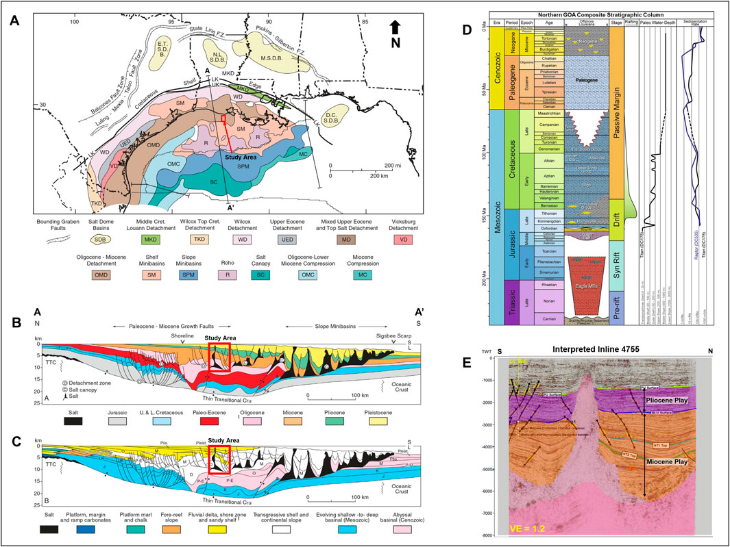
Figure 1. (A) Structural domains of the northern GOA modified from Galloway (2009); (B) North-south running cross-sections of the Northern GOA continental margin, modified from Galloway (2009); (C) Principal depositional facies associations, modified from Galloway (2009); (D) Generalized stratigraphic column of the northeastern GOA modified from Mattson et al. (2020); (E) Interpreted Inline 4,755, displaying a cross-sectional view of the region’s 3D stratigraphy and structural morphology. Note VE denotes vertical exaggeration.
Although viable reservoirs and aquifers for CO2 storage in sedimentary basins such as the GOA play a crucial role in advancing CCS technology and mitigating greenhouse gas emissions, the characterization of these subsurface reservoirs remains a significant challenge. Additionally, key uncertainties remain regarding the long-term behavior of injected CO2, including potential leakage pathways, geomechanical responses, and reservoir-caprock interactions (Chiaramonte et al., 2008; Rutqvist, 2012; Vidal-Gilbert et al., 2009; Birkholzer et al., 2012). The use of 3D seismic and well-log data can be used to understand in detail the structural and stratigraphic framework, trapping mechanism, reservoir quality, and sealing integrity of potential subsurface CO2 storage complexes (Hovorka et al., 2006; Hovorka et al., 2011; Hosseini et al., 2013; Meckel and Treviño, 2017). Historically, large-scale CCS projects have demonstrated the feasibility of CO2 injection and storage, with well-documented case studies such as Sleipner in Norway, In Salah in Algeria, and the Illinois Basin–Decatur Project in the United States (Chadwick et al., 2005; Rinaldi and Rutqvist, 2013; Bauer et al., 2016; Ringrose et al., 2021). Notably, these case studies highlighted the importance of detailed structural characterization using 3D seismic, as unexpected surface uplift and induced stress changes were observed during injection, resulting in seismic slip on pre-existing faults (Mathieson et al., 2011; Rinaldi and Rutqvist, 2013). In addition, several studies have evaluated the key factors influencing CO2 storage integrity, emphasizing the roles of fault reactivation due to pore pressure increase (Rinaldi and Rutqvist, 2013) and caprock sealing efficiency (Chadwick et al., 2005; Birkholzer et al., 2012). On the other hand, certain geological formations have historically been considered less favorable for CO2 storage due to complex reservoir structural heterogeneity and poor sealing capacity (Hovorka et al., 2006). According to Vidal-Gilbert et al. (2009), the complexity of fault systems and their associated in-situ stress conditions, as well as reservoir heterogeneity, can significantly influence CO2 migration and long-term containment due to associated induced seismicity, and these factors can be assessed and better constrained using geophysical monitoring techniques such as high-resolution 3D/4D reflection seismic-based subsurface characterization, given that faults typically act as migration pathways and induced seismic events are mainly associated with slip on preexisting faults. These factors can be better constrained by applying high-resolution reflection seismic structural architecture and stratigraphic framework characterization.
So far, CCS studies in the GOA have mainly focused on fluid flow simulations of modeled CO2 injection in various synthetic reservoir models, with limited comprehensive characterization of reservoir-scale geological heterogeneity and CO2 plume migration pathways using high-resolution reflection seismic and well-log data. As a result, there is considerable uncertainty regarding the impact of structural and stratigraphic complexities on CO2 storage efficiency, leakage risk, and induced seismicity potential. Addressing these uncertainties is critical for improving the reliability of CCS projects and holds significant potential benefits for advancing carbon sequestration technologies. This study aims to comprehensively characterize reservoir-scale structural heterogeneity, trapping mechanisms, and CO2 plume migration pathways, as well as investigate the storage potential for future CCS projects in the East Cameron Block of the northern GOA region through detailed subsurface mapping and volumetric analysis of suitable reservoirs for carbon dioxide sequestration using 3D reflection seismic and well data, in order to address the rising atmospheric CO2 levels stemming from simultaneous increase in energy consumption mainly supplied from fossil fuels. Our study bridges these gaps by providing a reliable characterization of fault architecture, reservoir framework, and sealing efficiency, which are critical for long-term CO2 storage security. We chose the East Cameron block due to access to 3D seismic data provided by the BOEM. Compared to earlier evaluations, this study offers better restrictions on fault geometry and storage capability through a thorough seismic-based reservoir characterization. Additionally, the consensus is that offshore storage is a more viable option because of its advantages, including significant storage space potential and a lower likelihood of legal challenges (Hills and Pashin, 2010; Roberts-Ashby et al., 2015).
2 Geologic setting
2.1 Gulf of America basin evolution and history
The Gulf of America (GOA) basin is an ocean basin located between the Yucatan block and the North American plate (Galloway, 2009). The formation of the GOA Basin region originated in the Late Triassic period when the North American plate rifted and initiated the breakup of the supercontinent Pangea, resulting in the separation of the North American plate from the South American and African plates and continued through the Early and Middle Jurassic Dice, 2017). The resulting seafloor spreading and crustal extension throughout the Mesozoic are the primary geologic events creating the structure of the basin (Sawyer et al., 1991; Buffler and Thomas, 1994; Harry and Londono, 2004; Jacques and Clegg, 2002; Galloway, 2009).
Mesozoic evolution of the northern GOA was fundamentally dominated by subsidence that was both systematic and thermally driven, as well as global sea level changes (Watts, 1982; Galloway, 2009; Alves et al., 2020). Early Jurassic Transgressions resulted in the deposition of sedimentary units in a coastal plane to the shoreface environment (Hudec et al., 2013; Roelofse et al., 2020). The middle Jurassic period was marked by the deposition of the Louann Salts from the evaporation of marine incursions entering from the west (Ewing, 1991; Dice, 2017); see Figures 1A–C. During the Late Jurassic and Early Cretaceous periods, periods of crustal cooling and continued subsidence both expanded and deepened the GOA (Dice, 2017). However, seafloor spreading resulted in the southward rifting of the Yucatan block (away from the North American plate), initiating the formation of oceanic crust in the central basin and separating the Middle Jurassic Louann Salt deposits (Ewing, 1991; Galloway, 2009 Dice, 2017). Post-rifting thermal subsidence and connection with the Atlantic Ocean caused an expansion of the basin (Hood et al., 2002; Roelofse et al., 2020). By the end of the Cretaceous period, seafloor spreading was over and a passive margin structure was established (Roelofse et al., 2020).
The primary geologic structure and configuration of the basin was completed by the end of the Late Cretaceous, however it was during the Cenozoic period that the primary sediment deposition and salt movement occurred (Galloway, 2009). The Laramide orogeny during the Paleogene resulted in large quantities of clastic sediments being deposited into the basin beginning in the Paleocene through the Middle Eocene (Galloway, 2009; Dice, 2017). Crustal heating and volcanism and resulting erosional uplift during the Late Eocene and Early Oligocene also fueled Oligocene and Miocene depositional sequences (Galloway, 2009). Pliocene through Holocene sedimentation is attributed to the Pliocene uplift of the western High Plains (Galloway, 2009).
2.2 Gulf of America structural composition and styles
The primary structural features present in the GOA basin area are salt basins and diapirs resulting from the Late Triassic rifting (Sassen et al., 1994). The aforementioned rifting also resulted in a series of grabens and half-grabens (Salvador, 1987; Roelofse et al., 2020). After the Laramide Orogeny deposited clastic sediments over the Louann Salts through the Cenozoic era, differential pressure gradients resulted in salt flow, causing the formation of salt diapers, pillows, domes, and ridges (Galloway, 2009; Dice, 2017). Additionally, structural traps were created due to the pressure of these salt structures (Nehring, 1991). Subsequently, stress regimes within prograding continental margins resulted in growth faults along shelf margins and compressional anticlines and reverse faults along the slope base of the basin (Dice, 2017). These salt features and structural traps acted as traps for hydrocarbons due to the juxtaposition of reservoir rocks against salt diapirs and impermeable shale rocks that act as seals (Ewing, 1991; Nehring, 1991). This prevents fluid migration across faults or salt diapirs, resulting in a productive hydrocarbon-rich basin (Dice, 2017).
2.3 Gulf of America stratigraphy
The generalized stratigraphy of the GOA basin is summarized in Figure 1D. The Eagle Mills Formation comprises continental red beds and volcanic rocks that infilled the previously mentioned Triassic grabens and half grabens (Salvador, 1987; Roelofse et al., 2020). The Louann Salt deposit is the primary feature of the Jurassic period, while the formation of carbonate platforms marks the Cretaceous due to the largely carbonate depositional system due to the development of massive-margin structure (Roelofse et al., 2020). Terrigenous sediments prograde over carbonates from volcanic activity that continued through the Late Cretaceous (Galloway, 2009). During the Paleogene, the deposition of clastic sediments, including sandstone, marine claystone, and continental deposits, from the Laramide orogeny resulted in the deformation and mobilization of salt, resulting in diapirs and other salt intrusions and basinward progression of major fault systems (Galloway, 2009; Roelofse et al., 2020). In the Neogene, inversion, further listric down to basin growth faults are visible in the deposited sandstone, and overall local thickening and thinning of sediments occurred due to salt diapirism (Galloway, 2009; Hudec et al., 2013). In the Pleistocene and Pliocene periods, primarily deltaic sediments and fine-grained clastic were deposited (Galloway, 2009).
2.4 East Cameron Block
In terms of tectonic setting, general sedimentation patterns within the East Cameron area have primarily been influenced by growth faulting and salt deformation (Wagner et al., 1994). The specific study area is within latitude 25° 40′ 52.0932″ N and Longitude 89° 53′24.4932″W. Figure 1 details the region’s location in the larger GOA basin and its stratigraphic and structural features. As summarized in Figure 1, salt diapirism and overpressured mudstones dominate the East Cameron block. They are associated with growth faults, salt bodies fracturing and welds, and pathways that extend from source rocks through overlying Cenozoic sediments and reservoirs. Primary plays are Pliocene and Miocene in age, and traps include faults, anticlines, salt diapirs, and stratigraphic and combination traps. Overall, these structural styles, in combination with the high-frequency nature of the depositional systems at work and deformed shelf margin and slope sediments, make correlation and interpretation of existing structures very difficult (Wagner, 1994).
3 Data availability and methodology
3.1 Available data
The interpreted database includes an area of full angle post stack time migrated (PTSM) three dimensional (3D) seismic volume selected within a large survey in the northern portion of the East Cameron Block GOA. The survey was acquired from the Bureau of Ocean Energy Management (BOEM), covering 3,902.6 Acres. The vertical sampling rate is 4s two-way-time (0–8 s), and bin spacing is 12.5 m by 20 m, which is considered high resolution 3D seismic volume, since variation in structural and stratigraphic features within such bin spacing is typically negligible. Included inline range is 2,800–10,275, and crossline range is 58,000–78,300. Additionally, a suite of wireline well logs obtained from BOEM was utilized, with the dataset including 13 rasters, 2 digital logs, and 5 checkshots later utilized for velocity modeling. Available well-log data included SP, gamma, resistivity, and biostratigraphic data; however, neutron, density, and sonic data were lacking.
3.2 Seismic interpretation
Seismic horizons corresponding to reservoirs were mapped using the Petrel standard geophysical software by applying integrative iterative attribute-assisted 3D seismic interpretation and subsurface mapping techniques. Fault identification and analysis were performed on every inline throughout the seismic volume incorporating Petrel’s variance-based semblance volume attribute to identify existing geologic structures and adequately unravel structural complexities. This attribute helps differentiate true fault terminations from seismic noise, strengthening our interpretation of fault networks within the CO2 storage complex. The high-resolution nature of the 3D seismic volume aided this integrated fault interpretation technique since low-resolution 3D seismic will result in pixelated attribute sections. The depleted oil reservoirs suitable for CO2 sequestration were identified by manually interpreting low gamma ray and high resistivity readings based on the well-log data. The identified reservoirs were then tied to specific seismic reflection characters/horizons using the time-depth relationship curves (checkshots) provided. Reservoir mapping was manually performed every five inlines and crosslines to ensure detailed and accurate structural characterization using Petrel. Horizon mapping started at well locations where target reservoir tops have been tied to specific seismic horizons (conventionally known as a well-to-seismic tie) and progressed until the horizon or reservoir surface was completely interpreted/mapped.
3.3 Velocity modeling and depth conversion
We proceeded to velocity modeling and depth conversion following the complete horizon mapping. Here, we calibrate available check shot data with the well tops manually identified from the available gamma and resistivity information. Subsequently, we utilized the calibrated checkshots to generate a linear velocity function that is then applied to model velocity across the mapped reservoir by incorporating the raw tow-way-time information contained in the time structure map. Finally, we incorporate the time structure map and generated velocity model in a standard mathematical relationship, such that:
where v is velocity and t is one-way time. The depth-converted maps are presented in the results section below. We acknowledge the limitation of using five checkshot wells for velocity modeling. However, the time structure maps for the reservoirs and regional surfaces interpreted show that structures identified in depth are consistent with the structures in time, validating the quality of the velocity model applied to depth convert the time maps.
3.4 Estimation of CO2 storage capacity
To estimate the number of tons of CO2 that could be associated with the depleted oil reservoirs interpreted, we carried out a comprehensive petrophysical and volumetric analysis of the identified and mapped depleted oil reservoirs and then utilized the oil volumes calculated to determine the equivalent CO2 storage capacity. Petrophysical parameters and volumetrics of the Miocene reservoirs mapped were computed by applying standard formulas described below to available well-log data. Well logs were utilized for petrophysical parameter estimates due to the lack of availability of core samples. However, it is important to know that the log-derived values are consistent with petrophysical properties typical of similar and nearby reservoirs in the GOA (Agartan et al., 2018).
where: Φ is porosity, ρma is matrix density (2.65 for sandstone), ρf is fluid density (0.925 i.e., Average for oil), and ρb = average/bulk density.
We calculate water saturation using a simplified version of Archie’s equation, commonly used in reservoir engineering and well log interpretation,
Where Sw is the fraction of pore space occupied by water in reservoir rock, expressed as a decimal or percentage known as water saturation, F is a dimensionless factor that describes how resistivity changes with porosity known as the formation factor, Rw is the resistivity (Ω·m) of formation water at reservoir conditions, which is influenced by salinity and temperature known as formation water resistivity, and Rt is the resistivity (Ω·m) of the formation as measured by well logs, which includes the effects of hydrocarbons and water known as True Resistivity of the Formation. This equation assumes Archie’s Law applies and that the formation does not contain conductive minerals like clays, which would require modifications such as the Waxman-Smits or dual-water models. After determining the petrophysical parameters needed to estimate storage capacity, we proceeded to determine the Original Oil in Place (OOIP) of viable structural closures on the reservoirs mapped.
In the case of depleted oil reservoirs, the equation below is used to calculate the OOIP. Such that:
Where: 7,758 is a conversion factor to adjust the volume to barrels, based on standard oilfield units, A is the area of the reservoir in acres, h is the net pay thickness of the reservoir in feet. This refers to the productive thickness that contributes to oil. Φ (phi) is porosity, a measure of the void spaces in the rock, expressed as a fraction or percentage. It indicates the portion of the reservoir rock that can store fluids; Sw is water saturation, which represents the fraction of the pore space occupied by water; the term (1−Sw) gives the fraction of the pore space filled with oil, Boi is the formation volume factor for oil, estimated from documented range for depleted hydrocarbon reservoirs in GOA (Agartan et al., 2018). It represents the volume of oil in the underground reservoir compared to the volume at the surface, and GCF is the gas cap factor, which is used if the reservoir has a gas cap that needs to be accounted for in the OOIP estimation. In the case of NT1 and NT2 reservoirs, there is no gas cap; therefore, GCF was taken to be 1, similar to reservoirs without gas caps, as documented in Agartan et al. (2018). This equation combines these parameters to estimate the amount of OOIP in the reservoir.
Subsequently, we apply the calculated OOIP to estimate the quantity of captured CO2 that can be stored in the structural closures characterized for the Miocene reservoirs identified and mapped through a step-by-step method described below. To determine how many tons of CO2 a structural geologic closure with a storage capacity designated by SC in millions of barrels of oil can hold, apply the following steps:
1. Convert Reservoir Capacity (OOIP) to Volume in Cubic Meters (VCM) such that 1 barrel (bbl) = 0.158987 m3. This implies that the VCM of
.
2. Apply CO2 Storage Efficiency Factor (SEF). The CO2 storage efficiency depends on the reservoir type (depleted oil/gas reservoirs or deep saline aquifers), porosity and permeability, and trapping mechanism (structural, mineralization, or stratigraphic). Typically, SEF ranges widely from 1% to 80% for depleted oil reservoirs in the GOA (Agartan et al., 2018). Given lack of access to the production data for the block, we apply an SEF of 4% characteristic of oil-bearing reservoirs in the GOA as documented by Agartan et al. (2018) for the structural closures identified for the mapped depleted oil reservoirs, which is reasonable for the study area, such that:
.
3. Convert CO2 volume to Mass. In typical geological storage scenarios, CO2 is injected at depths greater than 800 m to maintain supercritical conditions. At these depths, the temperature and pressure conditions generally result in CO2 densities ranging from approximately 600–800 kg per cubic meter (kg/m3) (Greene et al., 2008; Aydin et al., 2010). This is associated with the geothermal gradient in the GOA, which typically ranges from 25°C to 30°C per kilometer of depth (Aydin et al., 2010). Applying this gradient, northern GOA reservoirs at depths of 4,100 m to 5,100 m would have temperatures approximately between 102.5°C and 153°C, which agrees with the temperature results gotten for reservoirs in the region by Dessenberger et al. (2007). Therefore, in this final step we reliably assume that the supercritical CO2 to be injected into these depleted oil reservoirs will be at a density of ∼700 kg/m3. This implies that the capacity for CO2 storage measured in tons can be calculated for each structural closure identified, such that:
.
4 Results
4.1 3D seismic interpretation
Detailed examination and interpretation of fault geometries and orientations were carried out using Petrel software, and we found a complex network of antithetic and synthetic normal faults throughout the region. The interpreted crossline 75,000 (see Figure 2) and the interpreted inline 7,400 (see Figure 3) are presented below. These figures show an increased intensity of faulting and significant salt deformation at deeper stratigraphic levels. Additionally, we document the density of faults at various depths throughout the northern East Cameron block in the GOA. Mapping of target reservoirs identified from interpretation of well logs revealed that the northern GOA continental shelf reservoirs are primarily distinguished by growth fault bounded faulted roll-over anticlines with fault throws ranging from 30 m to 131 m, and a large salt-cored anticline trending northeast to southwest that was associated with several crestal collapse faults that segmented the reservoirs with no evidence of reservoir communication between segmented fault blocks (Figures 2, 3). The lack of reservoir communication is attributed to juxtaposition of reservoir rocks on impermeable shale formations due to adequate throw along faults. In sedimentary basins, fault throw often correlates with fault length, such that typically, longer faults exhibit larger throws (Schultz et al., 2006). A common ratio observed is between 1:10 and 1:30, meaning a fault 10 km long might have a throw between approximately 333 m and 1 km (Schultz et al., 2006). Previous studies in the GOA have documented faults with varying throws affecting reservoir sequences. For instance, Fachri et al. (2016) noted a major fault with a maximum throw of 478 m, while ancillary faults exhibited throws between 35 and 80 m, which agrees with the fault throw qualitatively observed in this study. Fault throws of 30–131 m observed here indicate potential sealing capacity, reducing CO2 migration risks. However, we recommend that future work incorporate geomechanical modeling to evaluate fault stability under CO2 injection pressures. We also note that the strata in the northern GOA region reveal large amounts of deformation due to salt diapirs. There is also evidence of inflation of the anticline resulting from the pressure on the marine salts. The Miocene sandstone reservoirs were covered by thick columns of shale and claystone, which act as regional seals, as well as several diapiric salt seals present due to the large salt body intrusions.
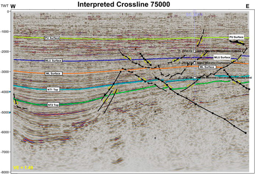
Figure 2. High-resolution cross section showing interpretation of Crossline 75,000 in Petrel, exhibiting synthetic and antithetic normal faults. Note VE denotes vertical exaggeration.
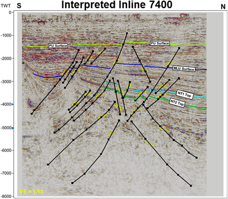
Figure 3. High-resolution cross section showing interpretation of Inline 7,400 in Petrel, exhibiting synthetic and antithetic normal faults. Note VE denotes vertical exaggeration.
4.2 Regional structural characterization
Two regional structure maps were produced in the East Cameron block using Petrel software (Figures 4, 5). The data was converted from a time scale to a depth scale using the provided checkshot time-depth relationship for five drilled wells, allowing for the creation of a detailed subsurface depth map and detailing the significant structural complexity within the study area. It is imperative to interpret the regional surface level prior to reservoir mapping when attempting to identify potential CO2 reservoirs for sequestration because the regional surfaces act as seals that trap the hydrocarbons in the field and must be identified. On the Upper Lower Miocene Level (Figure 4), the region was dominated by large, central salt deposits and ridges. As depth increased on the Lower Miocene Level (Figure 5), we found reduced faulting on the structural level, but increased salt intrusion and deformation of strata.
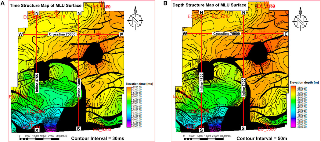
Figure 4. Regional structure maps of the Upper Lower Miocene level. (A) Time structure map. (B) Depth structure map.
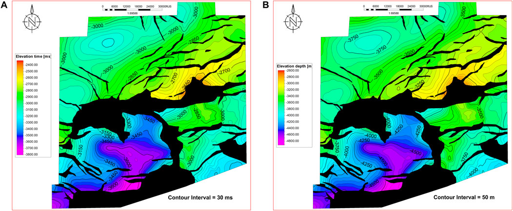
Figure 5. Regional structure maps of the Lower Miocene Level. (A) Time structure map. (B) Depth structure map.
Through a combination of 3D seismic data analysis techniques involving horizon mapping and structural interpretation of the different fault geometries and their subsequent orientations, we gained a more comprehensive and thorough understanding of the region’s 3D seismic structural architecture and its implications for CO2 sequestration and reservoir management. However, while structural closures provide potential CO2 traps, fault reactivation poses a risk to long-term storage integrity. Therefore, we recommend induced seismicity monitoring using downhole seismic sensors to analyze stress changes and estimate pore pressure increases throughout the CO2 sequestration operation life span.
4.3 Reservoir characterization
Two main reservoirs were characterized in the northern GOA region, based on data provided from well-log analysis and the petrophysical results obtained (Figure 6). The reservoirs were labeled NT2 (Figure 7) and NT1 (Figure 8). The time map was converted to a depth map using the checkshots to develop a reservoir velocity model. The resultant depth maps show that the structures in time are preserved in the depth domain, confirming the validity of the velocity model used (Figures 7, 8). Analysis of the interpreted target reservoir structural maps revealed over 20 structural closures that are favorable storage complexes for commercial CO2 sequestration (Figure 9), including an assessed best storage complex capable of storing 9.4 million metric tons of supercritical CO2 at 4% SEF (Figure 9D).
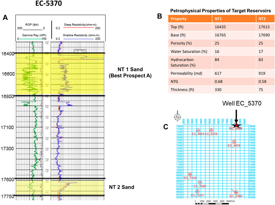
Figure 6. Well-log interpretation and petrophysical results of the target reservoirs. (A) Wireline log interpretation for Well EC-5370 showing gamma ray and resistivity values; (B) Petrophysical properties for NT1 and NT2 reservoirs; and (C) Base map of the study area showing the location of well EC-5370.

Figure 7. Structure maps of NT2 reservoir top. (A) Time structure map. (B) Depth structure map.
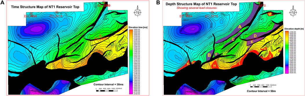
Figure 8. Structure maps of NT1 reservoir top. (A) Time structure map. (B) Depth structure map.
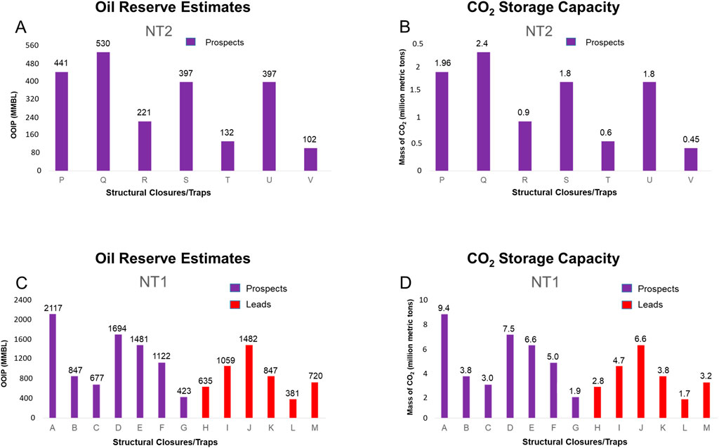
Figure 9. OOIP and equivalent CO2 storage capacity estimation for the target reservoirs. (A) OOIP estimates for NT2 reservoir; (B) Equivalent CO2 storage capacity for NT2 reservoir; (C) OOIP estimates for NT1 reservoir; and (D) Equivalent CO2 storage capacity for NT2 reservoir. Note that all CO2 storage capacity estimates are based on 4% SEF, as determined earlier, while the upper-case alphabets below the histograms represent the structural closures identified for NT2 and NT1 reservoirs in Figures 7, 8, respectively.
Mapped structures of the NT2 reservoir (Figure 7) showed a predominance of faulted anticlines and associated synclines bound to the south by salt diapirs and ridges. The different closure types present in the system were 3-way fault-bounded closures, 2-way fault-bounded closures, and 1-way faulted-bounded closures down dip. After analysis, we found 7 prospect closures. Reservoir characterization of NT1 (Figure 8) revealed similar structural characteristics. These also included faulted anticlines, associated synclines, which were bound to the south by salt diapirs and ridges, and closure types of 3-way fault-bounded closures, 2-way fault-bounded closures, and 1-way fault-bounded closures down dip. Prospects identified for CO2 storage are 15 in total.
5 Discussion
Our interpretation of the region is mainly consistent with previous research regarding the structural style, stratigraphic framework, hydrocarbon occurrence, and viability of identified depleted hydrocarbon reservoirs for CO2 storage. We found that the area has a high potential for CO2 storage, as it has layers of depleted hydrocarbon-bearing sandstone reservoirs of good porosity and permeability, which are paired with confining impermeable shales that act as structural traps and seals (DeAngelo et al., 2019). The East Cameron block in the Northern GOA is dominated by several hydrocarbon source rocks, which produce an abundance of hydrocarbons due to sufficient timely burial of the source rocks as a result of the complicated salt tectonics in the region (Ewing and Galloway, 2019). Furthermore, our findings of thick marine salt diapirs are in agreement with the morphology of salt diapirs identified in a previous study in the Northern GOA (Locker and Albert, 2019). Our analysis found that the region was dominated by synthetic and antithetic normal faults, and faulted rollover anticlines cored by salt, which was also consistent with the recent study by Snedden et al. (2020). The faults in the region act as traps, allowing for hydrocarbon production (Locker and Albert, 2019), which will further allow for future CO2 storage, as the sealing shales that keep hydrocarbon in can also prevent CO2 from leaking out and migrating to the sea floor, allowing it to be successfully sequestered (Dai et al., 2017). This is a reasonable qualitative characterization given that an unsealed structural closure will lack hydrocarbon accumulation. However, the well-log data displayed in Figure 6 shows high resistivity values for the NT1 and NT2 reservoirs, which clearly demonstrates hydrocarbon accumulation in these reservoirs, thereby confirming their sealability. Previous studies also show that shale rocks in the region act as top seals and trap-sealing elements for underlying hydrocarbon bearing reservoirs (Agartan et al., 2018; Snedden et al., 2020). Studies regarding the sealing abilities of this region have revealed that the Mass-Transport Complexes (MTCs) of the region and thick shale columns present in the northern GOA act as strong seals and permeability barriers for the hydrocarbons accumulating underneath (Wu et al., 2021). These shale columns are interpreted to provide similar seal ability for the reservoirs in the case of CO2 injection for storage. Research regarding the potential of depleted oil and gas fields present in the GOA has shown high potential for CO2 storage, including the possibility of storing 21.57 billion tons of CO2 in all active and depleted fields identified so far in the region (Agartan et al., 2018).
Based on the seismic interpretation, regional structural characterization, and reservoir characterization results presented in this study, we develop a conceptual 2D structural model (Figure 10), which comprehensively illustrates the structural framework, stratigraphic architecture, and trapping mechanisms of identified depleted oil reservoir prospects within the Northern East Cameron block in the Northern GOA. The 2D model shows the presence of synthetic and antithetic fault-bounded traps, acting as potential storage mechanisms for future CO2 sequestration. Our best CO2 storage opportunity was found in NT1 (Figure 11A), a depleted oil reservoir supported by a high resistivity value (Figure 11B), and reservoir marker expression in both seismic cross-sections displayed in Figures 11C, D. The structure is a 1-way fault-bounded closure in the central part, a 2-way fault-bounded closure in the northeast part, and a 3-way fault-bounded closure cumulatively. Based on the reservoir’s ability to seal and store large amounts of hydrocarbon due to the thick columns of sealing shales, sealability for CO2 storage potential is inferred to be high since these are depleted oil reservoirs. This is a reasonable inference because the accumulation of oil in these reservoirs, which is now depleted, confirms the sealability of the bounding faults. Due to the significant number of closures, the reservoirs mapped can house large amounts of CO2. Since the region is so close to the anthropogenic sources of CO2, it is a prime candidate for future storage projects. Volumetric analysis of the CO2 storage capacity shows that 9.4 million metric tons of supercritical CO2 could be stored in our best investment (i.e., closure with largest CO2 storage potential) structural closure, revealing huge opportunities for CO2 storage within the Northern East Cameron Block. Cumulatively, the closures identified have the capacity to store ∼70 million metric tons of supercritical CO2 at 4% SEF. This represents more than 100% of the total amount of supercritical CO2 captured and sequestered in subsurface geologic reservoirs within the United States since the geologic sequestration of CO2 began in 2016, according to EPA data. This storage potential and capacity exhibited by these Miocene reservoirs in the Northern GOA would mean significant positive progress from the perspective of reducing atmospheric greenhouse gasses, resulting in a future decrease in global warming. Reducing CO2 emissions into the atmosphere by capturing and sequestering CO2 in geologic reservoirs interpreted in this study will help reduce the greenhouse effect on our planet. This would be very beneficial in the fight to slow anthropogenic climate change and a huge step in the right direction regarding a greener and more sustainable future. While these findings highlight promising storage potential; future studies should incorporate dynamic reservoir simulation to refine risk assessments. Additionally, the effectiveness of the natural seals in the region must be carefully and continuously re-assessed to ensure long-term storage integrity, which will, in turn, aid in clearing the path for limited regulations for future CO2 sequestration projects in the collective effort by international and national, state and local governments to curtail global warming.
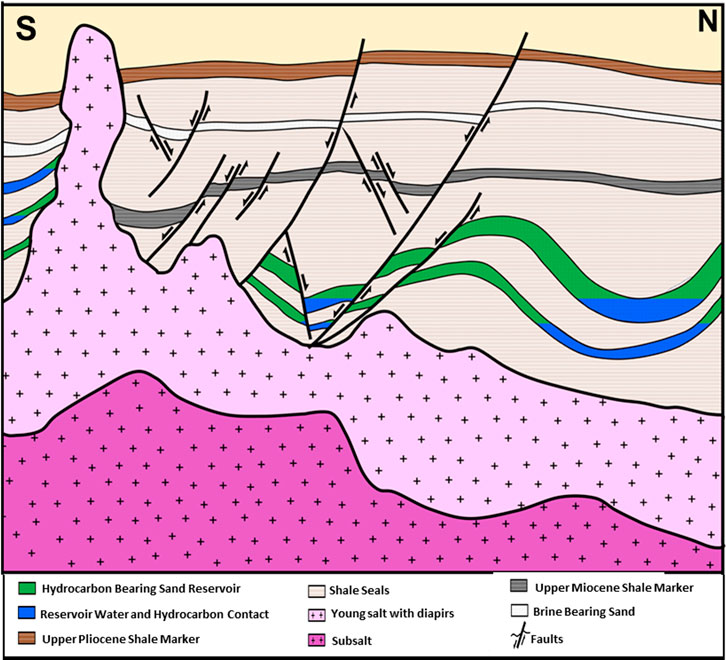
Figure 10. 2D structural model of the East Cameron block in the northern GOA developed from seismic and geologic observations. Note the model is not drawn to scale.
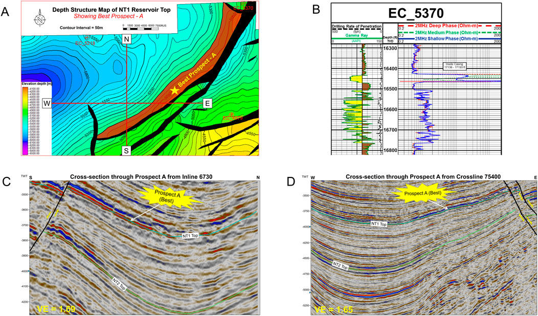
Figure 11. (A) Detailed depth structure map of NT1 reservoir top, with Prospect A showing large capacities for CO2 sequestration; (B) Resistivity log showing large hydrocarbon presence in Prospect A, indicating a capacity for CO2 sequestration; (C, D) High-resolution seismic cross-section showing the location of Prospect A and associated seismic structure. Note VE denotes vertical exaggeration.
6 Conclusion
This study utilized integrated iterative seismic interpretation, subsurface mapping techniques, and volumetric storage analysis to locate and analyze Miocene age reservoirs within the northern East Cameron Block, Gulf of America, in order to evaluate the region’s potential for CO2 storage as a means to mitigate anthropogenic climate change. Comprehensive mapping and analysis of these reservoirs have revealed complex strati-structural architecture and fault-sealed subsurface reservoirs within the selected Miocene layers, with the field showing significant capacity for CO2 storage. The main conclusions of this work are listed below.
• The information gathered from 3D seismic interpretation carried out in this study showed that strata of the Miocene age reservoirs in the northern GOA shelf are deformed by contractional salt-related folds with associated parasitic synthetic and antithetic normal faults resulting from crestal extension with the density of faulting increasing with depth throughout the studied block. We also document the presence of extensive salt tectonics exemplified by salt diapirs and inflated anticlines by the flow of the ductile and over-pressurized marine salts.
• The Northern GOA has high potential as a CO2 storage region, and several faulted subsurface reservoirs within the Northern East Cameron block were studied. The largest CO2 storage prospect was found in the NT1 reservoir, which had 9.4 million metric tons of supercritical CO2.
• We find 22 structural closures that are conducive storage complexes for commercial CO2 sequestration with a storage capacity of ∼70 million metric tons of supercritical CO2 assessed at 4% SEF. Within the two main reservoirs studied (NT1 and NT2), the different closure types present in the system were 3-way fault bounded closures, 2-way fault bounded closures, and 1-way faulted bounded closures down dip in both. They have trap styles of predominantly structural framework.
These results highlight the potential of this region as a viable location for future large-scale CO2 sequestration endeavors. The enormous available volumetric capacity of these reservoirs, in combination with regional seals and sealing faults, and proximity to major CO2 emission sources and existing oil/gas production and transportation infrastructure, makes the Northern GOA an ideal candidate for future CCS projects. Based on this, the GOA is inferred to be a key factor in United States and global efforts to reduce atmospheric CO2 concentrations with the ultimate goal of mitigating the greenhouse effect and slowing climate change. While our findings highlight significant CO2 storage potential in the GOA, we acknowledge uncertainties related to volumetric estimates, reservoir heterogeneity, and fault-related leakage risks. Future offshore CO2 storage projects will need to follow the guidelines set out by these findings, which call for more geomechanical modeling and long-term induced seismicity monitoring to improve risk assessments and the understanding of fault behavior during CO2 injection, ensuring the long-term integrity and sealability necessary for effective CO2 containment.
Data availability statement
Publicly available datasets were analyzed in this study. This data can be found here: https://www.boem.gov/oil-gas-energy/mapping-and-data.
Author contributions
MO: Data curation, Formal Analysis, Investigation, Methodology, Software, Validation, Writing – original draft, Writing – review and editing. OA: Investigation, Methodology, Software, Validation, Writing – original draft, Writing – review and editing. UA: Investigation, Methodology, Project administration, Resources, Software, Supervision, Validation, Visualization, Writing – original draft, Writing – review and editing, Conceptualization, Data curation, Formal Analysis, Funding acquisition. EU: Conceptualization, Data curation, Formal Analysis, Methodology, Software, Validation, Writing – review and editing. MH: Formal Analysis, Investigation, Methodology, Software, Writing – review and editing. DB: Formal Analysis, Investigation, Methodology, Software, Writing – review and editing. SB: Data curation, Formal Analysis, Investigation, Methodology, Validation, Writing – review and editing. AO: Data curation, Formal Analysis, Investigation, Validation, Visualization, Writing – review and editing. RK: Formal Analysis, Methodology, Software, Writing – original draft. CD: Formal Analysis, Methodology, Software, Writing – original draft. SP: Formal Analysis, Methodology, Software, Writing – original draft. CB: Formal Analysis, Methodology, Software, Writing – original draft.
Funding
The author(s) declare that financial support was received for the research and/or publication of this article. Research reported in this publication was supported in part by funding provided by the National Aeronautics and Space Administration (NASA), under award number 80NSSC20M0124, Michigan Space Grant Consortium (MSGC).
Acknowledgments
We also acknowledge the technical support of the Society of Exploration Geophysicists (SEG) Evolve program mentors.
Conflict of interest
Author OA was employed by Diversified Well Logging. Author EU was employed by Equinor.
The remaining authors declare that the research was conducted in the absence of any commercial or financial relationships that could be construed as a potential conflict of interest.
Generative AI statement
The authors declare that no Generative AI was used in the creation of this manuscript.
Publisher’s note
All claims expressed in this article are solely those of the authors and do not necessarily represent those of their affiliated organizations, or those of the publisher, the editors and the reviewers. Any product that may be evaluated in this article, or claim that may be made by its manufacturer, is not guaranteed or endorsed by the publisher.
References
Agartan, E., Gaddipati, M., Yip, Y., Savage, B., and Ozgen, C. (2018). CO2 storage in depleted oil and gas fields in the Gulf of Mexico. Int. J. Greenh. Gas Control 72, 38–48. doi:10.1016/j.ijggc.2018.02.022
Al Maqbali, Q., Hussain, S., Mask, G., and Xingru, W. (2023). “Numerical simulation of in-situ CO2 mineralization in mafic basaltic formations in southwest Oklahoma,” in Paper presented at the SPE Oklahoma City Oil and Gas Symposium, Oklahoma City, Oklahoma, USA, April 2023. doi:10.2118/213084-MS
Alves, T., Fetter, M., Busby, C., Gontijo, R., Cunha, T. A., and Mattos, N. H. A. (2020). A tectono-stratigraphic review of continental breakup on intraplate continental margins and its impact on resultant hydrocarbon systems. Mar. Petroleum Geol. 117, 104341. doi:10.1016/j.marpetgeo.2020.104341
Aydin, G., Karakurt, I., and Aydiner, K. (2010). Evaluation of geologic storage options of CO2: applicability, cost, storage capacity and safety. Energy Policy 38 (9), 5072–5080. doi:10.1016/j.enpol.2010.04.035
Bauer, R. A., Carney, M., and Finley, R. J. (2016). Overview of microseismic response to CO2 injection into the Mt. Simon saline reservoir at the Illinois Basin-Decatur Project. Int. J. Greenh. Gas Control 54 (Part 1), 378–388. doi:10.1016/j.ijggc.2015.12.015
Birkholzer, J. T., Cihan, A., and Zhou, Q. (2012). Impact-driven pressure management via targeted brine extraction—conceptual studies of CO2 storage in saline formations. Int. J. Greenh. Gas Control 7 (2012), 168–180. doi:10.1016/j.ijggc.2012.01.001
Buffler, R. T., and Thomas, W. A. (1994). “Crustal structure and evolution of the southeastern margin of North America and the Gulf of Mexico basin,” in Phanerozoic evolution of North American continent-ocean transitions. Editor R. C. Speed (Boulder, CO: Geological Society of America), 219–264. doi:10.1130/DNAG-COT-PEN.219
Chadwick, R. A., Arts, R., and Eiken, O. (2005). “4D seismic quantification of a growing CO2 plume at sleipner, North sea. Petroleum geology: north-west europe and global perspectives,” in Proceedings of the 6th petroleum geology conference, 1385–1399. doi:10.1144/0061385
Chiaramonte, L., Zoback, M., Friedmann, J., and Stamp, V. (2008). Seal integrity and feasibility of CO 2 sequestration in the Teapot Dome EOR pilot: geomechanical site characterization. Environ. Geol. 54 (8), 1667–1675. doi:10.1007/s00254-007-0948-7
Dai, Z., Zhang, Y., Stauffer, P., Xiao, T., Zhang, M., Ampomah, W., et al. (2017). Injectivity evaluation for offshore CO2 sequestration in marine sediments. Energy Procedia 114, 2921–2932. doi:10.1016/j.egypro.2017.03.1420
DeAngelo, M. V., Fifariz, R., Meckel, T., and Treviño, R. H. (2019). A seismic-based CO2-sequestration regional assessment of the Miocene section, northern Gulf of Mexico, Texas, and Louisiana. Int. J. Greenh. Gas Control 81, 29–37. doi:10.1016/j.ijggc.2018.12.009
Dessenberger, R., McMillen, K., and Lach, J. (2007). “Evaluating water-flooding incremental oil recovery using experimental design, middle Miocene to Paleocene reservoirs, deep-water Gulf of Mexico,” in AAPG Search and Discovery Article #40256, Extended abstract prepared for presentation at AAPG Annual Convention, Long Beach, California, April 1–4, 2007. Available online at: https://www.searchanddiscovery.com/documents/2007/08092dessenberger/index.htm.
Dice, M. E. (2017). A regional study of wilcox reservoirs in the deepwater northern Gulf of Mexico. Electronic Theses and Dissertations. University of Mississippi. Available online at: https://egrove.olemiss.edu/etd/1019.
Ewing, T. E. (1991). Structural framework, the Gulf of Mexico basin. Geological Society of America. doi:10.1130/DNAG-GNA-J.31
Ewing, T. E., and Galloway, W. E. (2019). “Evolution of the northern Gulf of Mexico sedimentary basin,” in The sedimentary basins of the United States and Canada, 627–694. doi:10.1016/b978-0-444-63895-3.00016-4
Fachri, M., Tveranger, J., Braathen, A., and Røe, P. (2016). Volumetric faults in field-sized reservoir simulation models: a first case study. AAPG Bull. 100 (5), 795–817. doi:10.1306/02011614118
Galloway, W. E. (2009). Chapter 15: depositional evolution of the Gulf of Mexico sedimentary basin. Sediment. Basins World 5, 505–549. doi:10.1016/s1874-5997(08)00015-4
Greene, T. J., O’Neill, B. E., Drumheller, R. E., Butaud, T., and Rodriguez, A. (2008). Challenges when predicting reservoir quality in the subsalt K2/K2-north field, green canyon, Gulf of Mexico: Gulf Coast association of geological societies transactions. 327–337. Available online at: https://www.researchgate.net/publication/268286848.
Harry, D. L., and Londono, J. (2004). Structure and evolution of the central Gulf of Mexico continental margin and coastal plain, southeast United States. Geol. Soc. Am. Bull. 116, 188–199. doi:10.1130/B25237.1
Hills, D. J., and Pashin, J. C. (2010). Preliminary evaluation of offshore transport and storage of CO2, prepared for southern states energy board. Geological Survey of Alabama, 11.
Hood, K. C., Wenger, L. M., Gross, O. P., and Harrison, S. C. (2002). “Hydrocarbon systems analysis of the northern Gulf of Mexico: delineation of hydrocarbon migration pathways using seeps and seismic imaging,” in Surface exploration case histories: applications of geochemistry, magnetics, and remote sensing, AAPG Studies in Geology No. 48and SEG Geophysical References Series No. 11, Tulsa, OK. Editors D. Schumacher, and L. A. LeSchack, 25–40. Available online at: https://www.searchanddiscovery.com/documents/hood/.
Hosseini, S. A., Lashgari, H., Choi, H. W., Nicot, J., Lu, J., and Hovorka, S. D. (2013). Static and dynamic reservoir modeling for geological CO2 sequestration at Cranfield, Mississippi, U.S.A. Int. J. Greenh. Gas Control 18, 449–462. doi:10.1016/j.ijggc.2012.11.009
Hovorka, S. D., Benson, S. M., Doughty, C., Freifeld, B. M., Sakurai, S., Daley, T. M., et al. (2006). Measuring permanence of CO2 storage in saline formations: the Frio experiment. Environ. Geosci. 13 (2), 105–121. doi:10.1306/eg.11210505011
Hovorka, S. D., Meckel, T. A., Treviño, R. H., Lu, J., Nicot, J., Choi, J., et al. (2011). Monitoring a large volume CO2 injection: Year two results from SECARB project at Denbury’s Cranfield, Mississippi, USA. Energy Procedia 4, 3478–3485. doi:10.1016/j.egypro.2011.02.274
Hudec, M. R., Norton, I. O., Jackson, M. P. A., and Peel, F. J. (2013). Jurassic evolution of the Gulf of Mexico salt basin. Am. Assoc. Petrol. Geol. Bull. 97, 1683–1710. doi:10.1306/04011312073
Indina, V., Fernandes, B. R. B., Delshad, M., Farajzadeh, R., and Sepehrnoori, K. (2024). “On the Significance of Hydrate Formation/Dissociation during CO2 Injection in Depleted Gas Reservoirs,” in Paper presented at the SPE Conference at Oman Petroleum and Energy Show, Muscat, Oman, April 2024. doi:10.2118/218550-MS
Jacques, J. M., and Clegg, H. (2002). Late Jurassic source rock distribution and quality in the Gulf of Mexico: inferences from plate tectonic modeling. Gulf Coast Assoc. Geol. Soc. Trans. 52, 429–440. Available online at: https://archives.datapages.com/data/gcags/data/052/052001/0429.htm.
Koehn, L., Romans, B. W., and Pollyea, R. M. (2023). Assessing Reservoir Performance for geologic carbon sequestration in offshore Saline Reservoirs. Energy Adv. 2 (12), 2069–2084. doi:10.1039/d3ya00317e
Locker, S. D., and Albert, C. H. (2019). “An overview of the geologic origins of hydrocarbons and production trends in the Gulf of Mexico,” in Scenarios and responses to future deep oil spills, 60–74. doi:10.1007/978-3-030-12963-7_4
Mathieson, A., Midgely, J., Wright, I., Saoula, N., and Ringrose, P. (2011). In Salah CO2 Storage JIP: CO2 sequestration monitoring and verification technologies applied at Krechba, Algeria. Energy Procedia 4, 3596–3603. doi:10.1016/j.egypro.2011.02.289
Mattson, A. G., Gani, M. R., Roesler, T., Gani, N. D., and Ford, J. T. (2020). 3D mapping of intruding salt bodies in the subsurface of the Gulf of Mexico using 3D seismic data. Results Geophys. Sci. 1–4, 100004. doi:10.1016/j.ringps.2020.100004
Meckel, T. A., Bump, A. P., Hovorka, S. D., and Trevino, R. H. (2021). Carbon capture, utilization, and storage hub development on the Gulf Coast. Greenh. Gases Sci. Technol. 11 (4), 619–632. doi:10.1002/ghg.2082
Meckel, T. A., and Treviño, R. H. (2017). Geological CO2 sequestration atlas of Miocene strata, offshore Texas state waters. The University of Texas at Austin, Bureau of Economic Geology, 74. Available online at: https://www.researchgate.net/publication/322602698_Geological_CO2_Sequestration_Atlas_of_Miocene_Strata_Offshore_Texas_State_Waters.
Meckel, T. A., Treviño, R. H., Hovorka, S. D., and Bump, A. P. (2023). Mapping existing wellbore locations to compare technical risks between onshore and offshore CCS activities in Texas. Greenh. Gases Sci. Technol. 13 (3), 493–504. doi:10.1002/ghg.2220
Meng, J., Pashin, J. C., Nygaard, R., and Chandra, A. (2018). Analysis of the stress field in the DeSoto Canyon Salt Basin for ensuring safe offshore carbon storage. Int. J. Greenh. Gas. Contr. 79, 279–288. doi:10.1016/j.ijggc.2018.11.006
Nehring, R. (1991). Oil and gas resources, the Gulf of Mexico basin. Geological Society of America. doi:10.1130/DNAG-GNA-J.445
Raza, A., Gholami, R., Rezaee, R., Bing, C. H., Nagarajan, R., and Hamid, M. A. (2018). CO2 storage in depleted Gas Reservoirs: A study on the effect of residual gas saturation. Petroleum 4 (1), 95–107. doi:10.1016/j.petlm.2017.05.005
Rinaldi, A. P., and Rutqvist, J. (2013). Modeling of deep fracture zone opening and implications for CO2 flow during geological storage at In Salah, Algeria. Int. J. Greenh. Gas Control 14, 200–212. doi:10.1016/j.ijggc.2012.10.017
Ringrose, P. S., Furre, A., Gilfillan, S. M. V., Krevor, S., Landrø, M., Leslie, R., et al. (2021). Storage of Carbon Dioxide in Saline Aquifers: Physicochemical Processes, Key Constraints, and Scale-Up Potential. Annu. Rev. Chem. Biomol. Eng. 12, 471–494. doi:10.1146/annurev-chembioeng093020-091447
Roberts-Ashby, T. L., Brennan, S. T., Merrill, M. D., Blondes, M. S., Freeman, P., Cahan, S. M., et al. (2015). Geologic framework for the national assessment of carbon dioxide storage resources─ South Florida Basin: chapter L in Geologic framework for the national assessment of carbon dioxide storage resources. U. S. Geological Survey, 2331–1258. doi:10.3133/ofr20121024L
Roelofse, C., Alves, T. M., and Gafeira, J. (2020). Structural controls on shallow fluid flow and associated pockmark fields in the east breaks area, northern Gulf of Mexico. Mar. Petroleum Geol. 112, 104074. doi:10.1016/j.marpetgeo.2019.104074
Rutqvist, J. (2012). The Geomechanics of CO2 Storage in Deep Sedimentary Formations. Geotech. Geol. Eng. 30, 525–551. doi:10.1007/s10706-011-9491-0
Salvador, A. (1987). Late Triassic-Jurassic paleogeography and origin of Gulf of Mexico. AAPG Bull. 71 (4), 419–451. doi:10.1306/2F917F19-16CE-11D7-8645000102C1865D
Sassen, R., Cole, G. A., Drozd, R., and Roberts, H. H. (1994). Oligocene to Holocene hydrocarbon migration and salt-dome carbonates, northern Gulf of Mexico. Mar. Petroleum Geol. 11 (1), 55–65. doi:10.1016/0264-8172(94)90009-4
Sawyer, D. S., Buffler, R. T., and Pilger, R. H. (1991). The crust under the Gulf of Mexico basin, The Gulf of Mexico Basin. Amos Salvador. doi:10.1130/DNAG-GNA-J
Schultz, R. A., Okubo, C. H., and Wilkins, S. J. (2006). Displacement-length scaling relations for faults on the terrestrial planets. J. Struct. Geol. 28, 2182–2193. doi:10.1016/j.jsg.2006.03.034
Snedden, J. W., Cunningham, R. C., and Virdell, J. W. (2020). The northern Gulf of Mexico Offshore Super Basin: Reservoirs, source rocks, seals, traps, and successes. AAPG Bull. 104 (12), 2603–2642. doi:10.1306/09092020054
Vidal-Gilbert, S., Nauroy, J. F., and Brosse, E. (2009). 3D geomechanical modelling for CO2 geologic storage in the Dogger carbonates of the Paris Basin. Int. J. Greenh. Gas Control 3 (3), 288–299. doi:10.1016/j.ijggc.2008.10.004
Wagner, J. B., Kofron, B. M., Morin, R. W., Ford, D. W., Mathur, V. R., and Mauro, R. T. (1994). “A sequence stratigraphic analysis of the Lower Miocene, West and East Cameron Areas, Gulf of Mexico,” in Submarine fans and turbidite systems—sequence stratigraphy, reservoir architecture and production characteristics Gulf of Mexico and international, 357–372. doi:10.5724/gcs.94.15.0383
Watts, A. B. (1982). Tectonic subsidence, flexure and global changes of sea level. Nature 297 (5866), 469–474. doi:10.1038/297469a0
Keywords: 3D seismic interpretation, reservoir characterization, prospect identification, CO2 sequestration, structural modeling, CO2 storage capacity
Citation: O’Donnell M, Anyiam OC, Anyiam UO, Uzuegbu EE, Hughes M, Beaty D, Bodunde SS, Osotuyi AG, Kagaju R, Dickey C, Penniall S and Bauer C (2025) 3D seismic structural characterization of faulted subsurface reservoirs in the northern East Cameron Block, Gulf of America continental shelf: implications for CO2 sequestration. Front. Earth Sci. 13:1577336. doi: 10.3389/feart.2025.1577336
Received: 15 February 2025; Accepted: 25 March 2025;
Published: 22 April 2025.
Edited by:
Muhammad Hammad Rasool, Universiti Teknologi PETRONAS, MalaysiaReviewed by:
Yeasin Arafath, University of Technology Petronas, MalaysiaSadam Hussain, The University of Texas at Austin, United States
Copyright © 2025 O’Donnell, Anyiam, Anyiam, Uzuegbu, Hughes, Beaty, Bodunde, Osotuyi, Kagaju, Dickey, Penniall and Bauer. This is an open-access article distributed under the terms of the Creative Commons Attribution License (CC BY). The use, distribution or reproduction in other forums is permitted, provided the original author(s) and the copyright owner(s) are credited and that the original publication in this journal is cited, in accordance with accepted academic practice. No use, distribution or reproduction is permitted which does not comply with these terms.
*Correspondence: Uzonna Okenna Anyiam, YW55aWFtQGhvcGUuZWR1
†These authors have contributed equally to this work and share first authorship