 Jihua Yao
 Yuanli Yang1,2*
 Mingwei Yang
- 1Hunan Institute of Water Resources and Hydropower Research, Changsha, China
- 2Hunan Dam Safety and Disease Prevention Engineering Technology Research Center, Changsha, China
Objective: Due to the dual influence of karst features in the dam site area and the unique characteristics of the dam soil, leakage issues in the dam body and dam foundation of a certain reservoir have persisted, limiting the effectiveness of the reservoir. Despite multiple attempts at anti-leakage reinforcement, the leakage problems have not been completely resolved and have worsened in recent years. The detection and identification of karst reservoir leakage should be conducted more accurately and simply.
Methods: This paper integrates the use of High-density resistivity method and Frequency-Division and Electrical Resistivity Tomography method for the detection and identification of leakage in the karst reservoir, complemented by geological surveys and geological drilling for verification.
Results: The leakage areas at the left and right ends of the dam base are caused by bypass seepage and contact leakage at the dam abutments. The perpetual water inflow in the sump wells at the middle and toe of the dam is mainly due to karst leakage in the dam foundation, leakage from the surface alluvial and depositional layers of the dam foundation, and contact leakage between the dam body and the dam foundation. Water seepage from within the culvert pipe body and its contact leakage with the dam body are the primary causes of scattered seepage on the fourth-level dam slope at the top of the power generation and irrigation culvert.
Conclusion: Integrated electrical method and geological methods can accurately diagnose the leakage risks in karst reservoirs. This comprehensive detection method is easy to operate, highly accurate, and widely applicable for identifying leakage risks in similar earth-rock dam karst reservoirs.
1 Introduction
The benefits of karst reservoirs are often not effectively utilized due to issues such as dam body leakage, dam foundation leakage, bypass seepage at dam abutments, or reservoir leakage, resulting in insufficient water retention throughout the year during operation. Among them, dam foundation seepages, dam abutment seepages and reservoir area seepages are mostly caused by karst seepages, while dam body seepages are mainly due to issues such as poor local impermeability of the filled soil or quality defects within the dam. These seepage risks can cause significant damage to dams, including infiltration, slope instability, and breaches that result in catastrophic disasters. The comprehensive geophysical exploration method can effectively detect the leakage risks in karst reservoirs and carry out targeted anti-leakage reinforcement measures, ensuring the safe operation of the dam.
For this purpose, many scholars have conducted theoretical and practical research on the identification and diagnosis of leakage problems in karst reservoirs based on single geophysical exploration methods (Jiang et al., 2020; Zhang et al., 2018) or comprehensive geophysical exploration methods (Peng, 2016; Yao et al., 2014). The main research objects include leakage sources in the dam site area (He, 2000; Jian and Sun, 2020; Yao et al., 2020), leakage channels within the dam body (Zhang et al., 2023; Zhao et al., 2022; Cui et al., 2024), quality defects (Wang et al., 2024; Yao et al., 2023; Liu et al., 2023), and leakage outlets (Bukowska-Belniak and Lesniak, 2017; Xu et al., 2020). The development and application of comprehensive geophysical exploration techniques for detecting hidden dangers in water conservancy and hydropower engineering are analyzed and summarized (Xu et al., 2022; Liu et al., 2019). Karst leakage issues in some karst reservoirs have been successfully resolved during construction or operation phases.
However, after the construction of a reservoir dam in a karst area, the identification and diagnosis of its leakage hazards not only require considering the uncertainty, diversity, and complexity of karst development in the dam site area (Zhen, 2018), but also necessitate addressing issues such as quality defects within the dam body, as well as leakage at the contacts between the dam body and its internal structures, and between the dam body and the dam foundation. These factors render the diagnosis of leakage hazards particularly challenging (Ren et al., 2014; Liu, 2022). Therefore, it is highly necessary and urgent to explore an effective, accurate, and operable multi-source fusion identification and diagnosis method for leakage hazards in karst reservoirs.
The occurrence of leakage often results in changes and anomalies in the physical characteristics of the dam (Sun et al., 2024). Due to the inherent limitations of a single geophysical exploration method, the revealed physical characteristics of the site are often one-sidedness and ambiguity, which leading to deviations or errors in the spatial location information of leakage hazards in reservoirs. The integrated geophysical exploration method can obtain multiple physical property detection results for karst reservoirs, it can reduce ambiguity, eliminate the false and retain the true, and serve as a mutual complement. This allows for a more accurate inversion of leakage hazards in karst reservoirs.
This paper comprehensively employs High-density resistivity method and Frequency-Division and Electrical Resistivity Tomography method (FD-ERT method), complemented by geological surveys and geological drilling results for verification, to diagnose and expose the developmental characteristics and causes of these leakage hazards. It is hoped to provide practical application experience for similar projects.
2 Methods
2.1 High-density resistivity method
High-density resistivity method is an array-based resistivity measurement method that combines electrical exploration techniques with computer digital technology. It integrates the characteristics of both electrical profiling and electrical sounding, enabling the revelation of lateral and vertical electrical variations in the rock and soil mass within a certain depth range underground (Peng et al., 2024). When leakage channels, voids, defects, or significant differences from the surrounding area exist in the buried rock and soil mass, the resistivity in these areas will exhibit obvious anomalies, with results significantly higher or lower than normal. Therefore, this method can be used to detect the approximate locations of leakage channels or defects in the rock and soil mass (Zhang et al., 2024; Li et al., 2024).
2.2 FD-ERT method
The operational principle diagram of instrument of FD-ERT method is shown in Figure 1. Firstly, instrument of FD-ERT method is set up to arrange the receiving electrodes in an array. An electrical transmitter capable of simultaneously emitting three independent current signals of different frequencies is used to send three current signals of different frequencies at one time. Three power supply points A1, A2, A3, and three infinite power supply electrodes B1, B2, B3 are arranged. Then, the electrical receiver collects the total electric field signals from each adjacent receiving electrode M and N, and separates these signals. By inputting the three-dimensional coordinates of each electrode and the current values of different frequencies, the apparent resistivity values can be calculated according to Equation 1. During the electrode movement, by shifting the three power supply electrodes A1, A2, and A3 collectively to the right, apparent resistivity data at different depths can be obtained, ultimately forming a measurement profile (Liu, 2022).
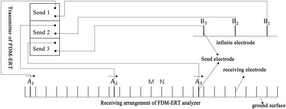
Figure 1. Operational principle diagram of FD-ERT method.
FFD-ERT method primarily employs a three-pole array, utilizing copper electrodes with a diameter of 50 mm, a length of 300 mm, and spacing ranging from 0.5 to 1.0 m. The three distinct current signal frequencies are 10Hz, 4Hz, and 1Hz, respectively. The signal separation algorithm adopts the extraction of odd harmonic signals from the received signals, and employs the difference quotient formula to obtain electric field information of the same frequency at different measurement points.
According to the formula for calculating apparent resistivity in the direct current resistivity method:
Where:
It is evident that simultaneous power supply from multiple points in the frequency-division electrical method can significantly enhance the efficiency and accuracy of identifying and diagnosing leakage issues in dam bodies and foundations. Based on the significant differences in resistivity among dam fill, leakage pathways, and the rock masses of dam foundations and abutments, the interpretation of leakage issues within the dam body, foundation, and abutments can be achieved. Generally, relatively low-resistivity areas indicate the presence of leakage issues.
2.3 Geological method
Geological methods employ techniques such as geological surveys, geological drilling, and water injection tests within boreholes to obtain information about the landform characteristics, stratigraphic lithology, geological structure, hydrogeological conditions, dam stability, and current state of leakage under the dam within the project area. It also involves drilling to ascertain the composition, compactness, and permeability of the dam fill soil. Additionally, laboratory soil tests are conducted to obtain the physical parameters of the rock and soil mass in the dam site area, which are then used to analyze the locations of leakage inlets, leakage pathways, and leakage exit zones in the dam.
Geological surveys are guided by geology and related sciences. Through observation and research, they investigate information such as leakage, cracking, deformation and landslides of the exposed surface, karst development, and hydrogeological conditions within the dam site area.
Geological drilling involves using drilling rods, drilling tools, and other equipment to bore vertically downwards from the dam crest into the dam body and foundation. This process aims to obtain core samples of the geotechnical materials (soil and rock) within the dam body and foundation, as well as to gather information about their properties, structure, composition, and water content.
The water injection test within boreholes refers to a test where water is injected into boreholes drilled in the dam. By regularly measuring relevant parameters such as the injection rate, time, and water level, the permeability coefficients of the dam body, the contact zone between the dam body and foundation, and the rock mass of the dam foundation can be determined.
3 Engineering applications and experimental scheme
3.1 Project overview
A reservoir is located upstream of the Songbai River, a tributary of the Youshui River, which is a first-tier tributary of the Yuanjiang River. It is a karst reservoir with a dam made of homogeneous red clay. The dam crest elevation is 741.64 m, the normal water level is 738.08 m, the maximum dam height is 31.64 m, and the dam crest axis is 434 m long. It is a key medium-sized water conservancy project with comprehensive benefits, primarily focusing on flood control and irrigation, while also accommodating power generation, water supply, aquaculture, and other functions. The bedrock in the dam area is composed of dolomitic limestone belonging to the middle-upper Loushanguan Group of the Cambrian System (∈2 + 3Ls), Karstification is extremely developed, with solution channels, solution holes, and caves visible on the surface, accompanied by karst pinnacles. The dam fill soil is red clay, which exhibits characteristics such as swelling upon water absorption, shrinking upon water loss, high liquid limit and plastic index, and difficulty in controlling compaction. Numerous desiccation cracks have been found on the downstream dam slope, some of which extend approximately 30–80 cm into the dam. Since its completion and operation, the reservoir has been plagued by issues such as dam body leakage, dam foundation leakage, and bypass seepage at the dam abutments. Despite multiple risk removal and reinforcement efforts, serious leakage problems still persist, hindering the full utilization of the reservoir’s benefits. The plan view and profile view of the dam are detailed in Figures 2, 3.
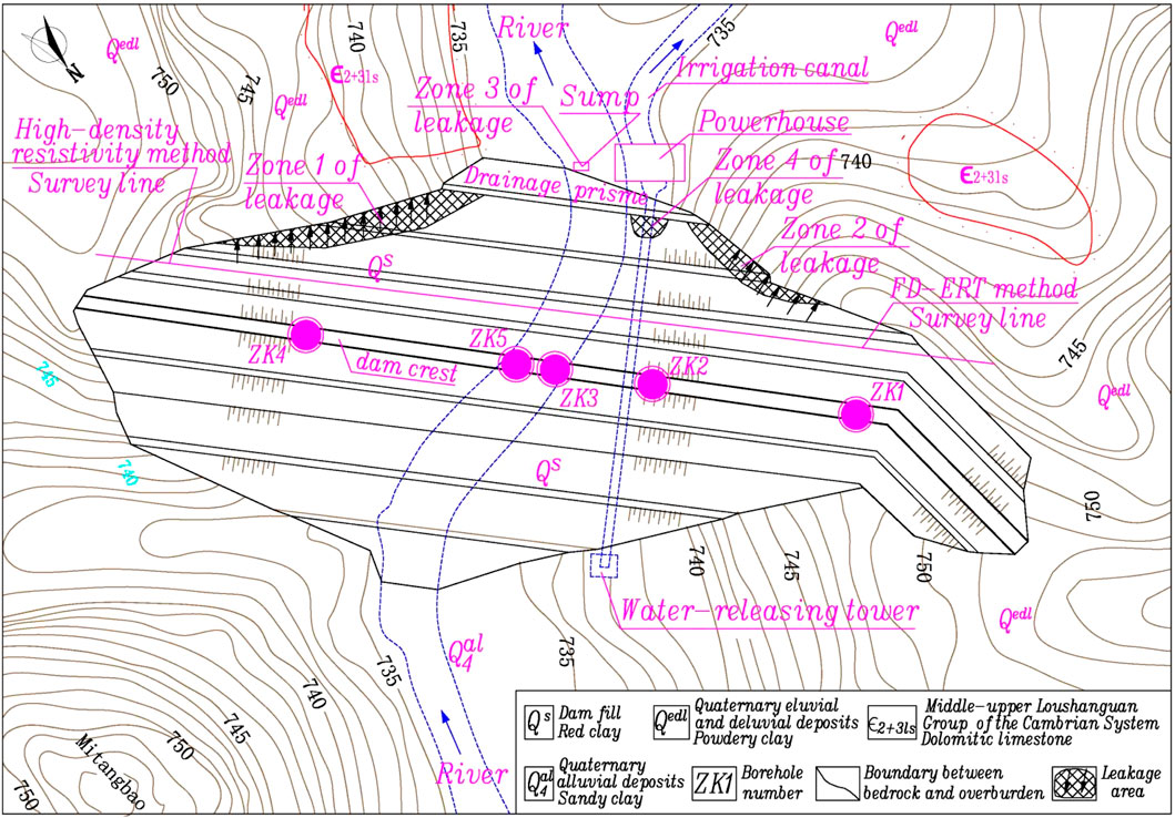
Figure 2. Layout diagram of survey lines and location map of leakage risks in the dam.
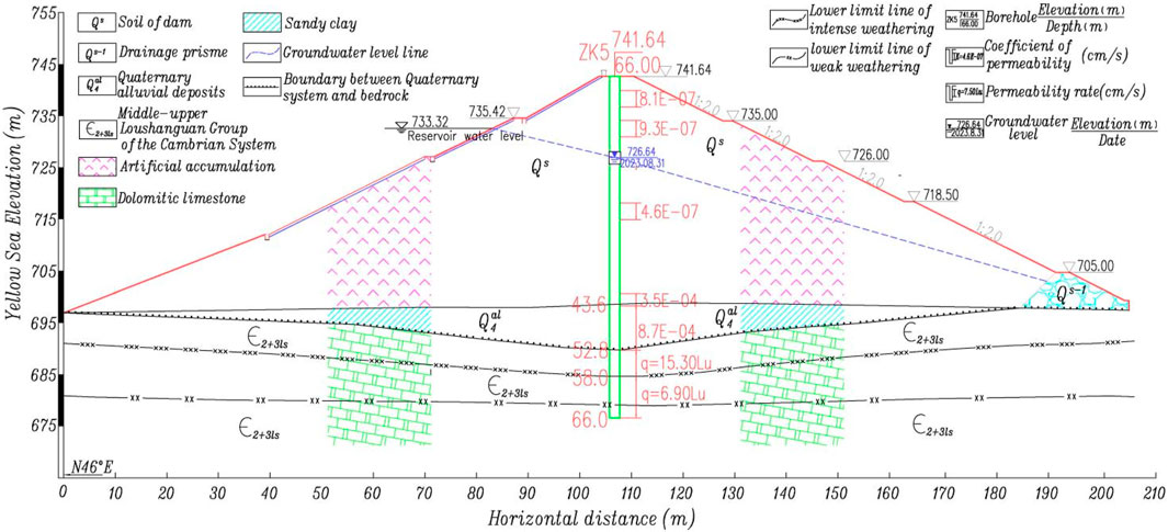
Figure 3. Longitudinal section at the centerline of the dam body.
On 18 August 2023, when the reservoir water level was at 733.32 m, we conducted an exhaustive geological survey and inspection of the leakage risk indications in the dam site area. Field geological investigations revealed that there was abutment seepage around both the left and right dam abutments below elevations of approximately 728.0 m and 724.0 m, respectively. The total seepage volumes amounted to approximately 0.5 L/s and 0.3 L/s, respectively. Additionally, near the areas of concentrated abutment seepage, there were large areas of dispersed seepage with multiple concentrated leakage points on the third and fourth-grade downstream slopes at both ends of the dam body. The dispersed seepage areas measured approximately 30 m2 and 18 m2, with total seepage volumes of 0.25 L/s and 0.1 L/s, designated as Leakage Area 1 and Leakage Area 2, respectively. Meanwhile, there was a sump well at the middle of the dam toe from which water flowed continuously throughout the year, with a seepage rate of approximately 0.8 L/s, labeled as Leakage Area 3. There was also a dispersed wet area measuring approximately 12 m2 on the fourth-grade downstream slope at the top of the power conveyance culvert outlet section, though no concentrated leakage points were observed, designated as Leakage Area 4. Notably, the leakage volumes at these leakage risk points exhibited a high correlation with the reservoir water level, disappearing partially during low water levels but significantly increasing in terms of both dispersed seepage area and concentrated leakage volumes during high water levels, posing a serious threat to dam safety.
Therefore, there are issues such as dam body leakage, dam foundation leakage, and bypass leakage at the dam abutments within the dam site area. Traditional geological methods struggle to interpret information about leakage sources, leakage pathways, and leakage outlets in the dam site area, making it difficult to implement targeted anti-leakage reinforcement measures for the leakage hazards. However, the integrated geophysical exploration method based on High-density resistivity method and frequency-division electrical method can effectively and accurately diagnose the spatial information of potential leakage hazards. Coupled with field geological surveys and geological drilling results for verification, it can ascertain the developmental characteristics and causes of various leakage hazards.
3.2 Geophysical and lithological characteristics of the engineering projects
To obtain the electrical characteristics of the rock and soil in the dam site area, undisturbed samples were taken by drilling cores from the dam body fill, dam foundation, and dam abutment rock masses. Resistivity measurements were conducted on the rock and soil masses in the dam site area. The sampling locations for the dam body soil cores were evenly distributed from the dam top to the dam bottom and from the left bank to the right bank. Similarly, the dam foundation and dam abutment rock cores were evenly distributed from highly weathered to slightly weathered materials. The geophysical exploration parameters are shown in Table 1.
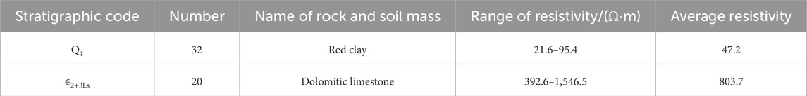
Table 1. Resistivity of rock and soil masses in the engineering area.
The electrical characteristics of the rock and soil masses in the dam site area are as follows: the dolomitic limestone of the middle-upper Loushanguan Group of the Cambrian System (∈2 + 3) exhibits medium to high resistivity, with an average resistivity of 803.7 Ω m; the red clay of the dam body exhibits low resistivity, with an average resistivity of 47.2 Ω m. It can be seen that there are significant electrical differences between different rock and soil masses, providing a prerequisite for electrical exploration.
3.3 Experimental scheme
A comprehensive approach was employed at the site, utilizing frequency-division electrical method, high-density resistivity method, and infrared thermography to identify the location information of leakage hazards in the dam area and analyze their causes.
(1) The equipment used in this experiment includes high-density resistivity meters and frequency-division electrical method instruments. All measurement points were laid out using high-precision RTK-GPS. Due to the lack of control points at the site, the GPS parameters adopted the China Geodetic 2000 (CGCS 2000) coordinate system, with a central meridian of 111°. The high-density resistivity meter used was manufactured by Chongqing Geological Instrument Factory, with the model number DUK-2A. For this experiment, one high-density resistivity survey line and one frequency-division electrical survey line were set up. In order to enable comparison between the results of the two measurement methods, the survey lines for both methods were arranged at the same locations, extending from the mountain at the right abutment downstream of the dam to the first-level downstream slope of the dam body, until reaching the mountain at the left abutment. The point spacing for the high-density resistivity survey line was 5 m, and for the frequency-division electrical survey line, it was 20 m. The primary objective was to detect the spatial locations of leakage hazards within the dam body, dam foundation, and both dam abutments. The details are shown in Figure 2.
(2) Based on the suspected problematic areas in the dam site zone diagnosed by the integrated electrical method, geological drilling was conducted for exposure and verification to further identify the sources of leakage in the dam body, dam foundation, and dam abutments. The drilling results were then compared, verified, and complemented with the detection results from the two electrical methods to thoroughly ascertain the causes of leakage in various seepage areas within the dam site zone.
4 Results and discussion
4.1 Results and analysis of high-density resistivity method
The detection results of the high-density resistivity survey line are shown in Figure 4.
(1) Low resistivity zones exist at measurement points 415 to 455 with elevations ranging from 730 m to 720 m, and at measurement points 455 to 515 with elevations from 725 m to 715 m. A high resistivity zone that lifts upwards is found near measurement point 525. Low resistivity zones also exist at measurement points 520 to 570 with elevations ranging from 730 m to 725 m, and at measurement points 555 to 580 with elevations from 715 m to 705 m. A high resistivity zone that lifts upwards is observed near measurement point 645. Low resistivity zones are present at measurement points 590 to 625 with elevations ranging from 720 m to 712 m, and at measurement points 630 to 675 with elevations from 723 m to 718 m. Based on pre-dam construction data, the dam between measurement points 380 and 700 was originally formed by connecting three small hilltops. Specifically, the vicinity of measurement point 470 is a low saddle on the right bank, the area near measurement point 560 is the old riverbed of Songbai River, and the vicinity of measurement point 645 is a small hill on the left side.
(2) The overall dam body exhibits low resistivity zones dominated by yellow, yellow-green, and green colors, with a resistivity approximately ranging from 30 to 150 Ω m, which is relatively consistent with the resistivity measured in the dam’s soil core. However, the resistivity in the low saddle area of the right dam abutment, the old riverbed of Songbai River in the middle, and the small hill area of the left dam abutment is significantly lower. Among these, the resistivity in the small hill area of the left dam abutment is the lowest, with some local areas already appearing as blue zones. This indicates that the water content in the dam fill at these locations is significantly higher, leading to enhanced electrical conductivity. These areas may represent leakage zones within the dam, and their elevations are relatively consistent with the leakage zones at the left and right ends of the dam.
(3) From the left dam abutment to the right dam abutment, a yellow-orange low-resistivity zone with a resistivity of approximately 200–300 Ω m exists on the surface of the dolomitic limestone at the bottom of the contact surface between the dam and its foundation. This resistivity is significantly lower than the measured resistivity of dolomitic limestone cores obtained from laboratory tests. The thickness of this low-resistivity zone is approximately 3.0 m, within which the water content of the dolomitic limestone and the activity of groundwater are significantly higher than those in the deeper rock mass. Preliminary speculation suggests that karst or joint fissures may have developed within the dolomitic limestone in this area, leading to a higher water content, more active groundwater, enhanced conductivity, and lower rock resistivity at this location. However, based on the exposed rock mass and stone buds in the dam site area, the joint fissures are not well developed, but karst is extremely developed. Therefore, it can be further determined that karst development exists within the rock mass with a thickness of approximately 3.0 m at the shallow surface of the dam foundation, and there are karst leakage pathways.
(4) The deep rock mass of the dam foundation is mostly composed of high resistivity zones with orange-red and red hues, featuring a resistivity greater than 500 Ω m. This indicates that the deep rock mass of the dam foundation is well-integrated, with low water content in the rock mass. The groundwater is inactive, exhibiting weak conductivity. Karst development is minimal, and the possibility of the development of caves and underground rivers within the rock mass is extremely low.
(5) A low resistivity zone appears at an elevation of approximately 670 m within the deep part of the small hill on the left dam abutment, indicating that groundwater is relatively active at this location. This suggests the presence of a karst cave or an underground river.
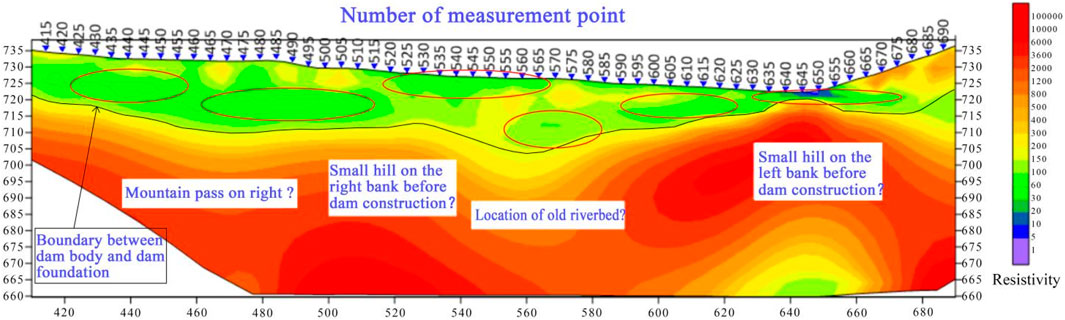
Figure 4. Inversion map of diagnostic results obtained by high-density resistivity method in the dam (The red circles in the diagram indicate leakage zones).
4.2 Results and analysis of FD-ERT method
The detection results of FD-ERT method survey lines are shown in Figure 5.
(1) The diagnostic results are generally consistent with those obtained by High-density resistivity method, but the frequency-division electrical method demonstrates significantly better detection accuracy for the deep dam body, dam foundation, dam abutment rock and soil mass, and their interfaces, especially in revealing the original topography of the dam foundation. However, High-density resistivity method offers superior detection accuracy for shallow rock and soil masses compared to the frequency-division electrical method. The main reason for this is that the measuring point spacing for High-density resistivity method is 5 m, while it is 20 m for the frequency-division electrical method. Therefore, the latter has lower sensitivity to shallow features compared to the former.
(2) There is a green low-resistivity zone at measurement points 425 to 460 with an elevation of approximately 730 to 724 m, and at measurement points 445 to 510 with an elevation of approximately 726 to 714 m in the right dam section. Similarly, in the left dam section, there are low-resistivity zones at measurement points 580 to 610 with an elevation of approximately 714–724 m, and at measurement points 630 to 640 with an elevation of approximately 715–721 m. Preliminary speculation suggests that these areas have high water content in the fill soil within the dam body, resulting in strong conductivity, and may represent leakage disease zones within the dam.
(3) There are noticeable relatively low-resistivity zones in both the dam body and dam foundation at measurement points 535 to 560 in the middle of the dam. At an elevation of approximately 725 to 718 m, there is a leakage disease in the dam body. Within the range of approximately 718 to 660 m in elevation, there exists an ancient low-lying corrosive gully in the dam foundation, which was an old riverbed. Before the dam was constructed, it was filled with Quaternary overburden, leaving behind permeable weak zones or pathways. These are located roughly in the same longitudinal position as the water collection well behind the dam. Preliminary speculation suggests that the continuous water inflow in the water collection well behind the dam may originate from the leakage in the dam foundation and dam body at the location of this old riverbed.
(4) Beneath the contact surface between the dam body and the dam foundation, there exists a continuous layer of yellow to orange-yellow low-resistivity zone with a thickness of approximately 3.0 m on the surface of the dam foundation rock and soil. This may be due to the development of karst features such as solution pores, caves, solution holes, or sinkholes in the dolomitic limestone at the surface of the dam foundation. The presence of karst leakage pathways results in high water content in the surface rock mass of the dam foundation, active groundwater, and enhanced conductivity.
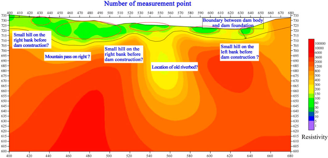
Figure 5. Inversion map of diagnostic results obtained by FD-ERT method in the dam (The red circles in the diagram indicate leakage zones).
4.3 Results and analysis of geological method
Based on the comprehensive analysis results of the two electrical methods, five boreholes were drilled on the dam crest, located at the right dam abutment, the top of the power generation and irrigation culvert, the old riverbed in the middle of the dam, and the left dam abutment, numbered ZK1 to ZK5 respectively (specific locations are shown in Figure 1). The objectives were to ascertain the soil composition and permeability of the dam body, the permeability of the contact zone between the dam body and the dam foundation, the permeability of the rock mass in the dam foundation, and the permeability of the contact zone between the dam body and the culvert pipe. By combining the locations and scales of Leakage Areas 1 to 4 obtained from the field geological survey, as well as the karst development of the exposed rock mass near the dam area, a comprehensive assessment of the leakage situation in the dam site area was conducted, and the causes of the leakage were analyzed.
(1) Based on the results of the geological drilling and water injection tests conducted at the site, the fill structures of the dam body revealed by ZK1, ZK3, ZK4, and ZK5 were relatively dense, with permeability coefficients all less than 1.0E-6 cm/s, indicating low permeability and good anti-seepage performance. Therefore, the possibility of leakage risks and pathways existing in the dam body (excluding the area surrounding the culvert within the dam) is relatively low. However, the permeability coefficients of the contact zones between the dam body and the dam foundation for ZK1 to ZK5 were 7.2E-4 cm/s, 2.3E-4 cm/s, 3.1E-4 cm/s, 2.8E-4 cm/s, and 8.6E-4 cm/s, respectively, all indicating moderate permeability and poor anti-seepage performance. Especially at the locations of ZK1 and ZK4, it was evident that the anti-seepage performance of the contact zones between the dam body and the dam foundation was poor, resulting in leakage at these contact zones. Additionally, the permeability coefficient of the dam body soil in the section from an elevation of 705 m–700 m at ZK2 was 4.9E-4 cm/s, indicating moderate permeability and poor anti-seepage performance. The permeability coefficients of the dam body soil in other sections were all less than 1.0E-6 cm/s, indicating low permeability and good anti-seepage performance. The elevation of the culvert floor adjacent to the left side of ZK2 was approximately 702.43 m, revealing poor fill quality and anti-seepage performance around the culvert within the dam, which resulted in leakage at the contact between the culvert and the dam body.
(2) During the investigation, the reservoir water level was recorded at 733.32 m, while the stable water levels within boreholes ZK1 to ZK5 were 727.28 m, 726.76 m, 726.62 m, 727.52 m, and 726.64 m, respectively. Combining these data with the elevations of low-resistivity zones revealed by two electrical methods, as well as the locations and elevations of leakage zones 1 to 4, it can be inferred that there is a significant gradient descent and clear connectivity among the reservoir water level, stable borehole water levels, low-resistivity zone elevations from electrical profiling, and the elevations of leakage zones 1 to 4. Evidently, the detection results from the two electrical methods are in good agreement with the actual conditions.
(3) Based on the results of the field geological survey, karst development in the exposed bedrock surface at the dam site is extremely pronounced, with karst gullies, cavities, and caves visible on the surface, accompanied by stone sprouts. It can be inferred that karst development in the surface rock mass of the dam foundation and abutments is also extremely pronounced. There are many well-connected karst leakage channels within the surface rock mass, indicating potential risks of leakage in the dam foundation and abutments.
(4) The low resistivity zones revealed by the two electrical methods within the downstream dam slope and dam body align well with the locations of leakage zones 1 to 4. Combining the results of in-hole water injection tests conducted on-site at the dam body and the contact zone between the dam body and dam foundation, it is likely that the leakage water in zones 1 to 4 does not solely originate from the dam body itself, but rather is a combined result of bypass leakage from the dam abutments, dam foundation leakage, leakage at the contact between the dam body and culverts, and leakage at the contact between the dam body and dam foundation. Additionally, some leakage water bypasses and infiltrates into the shrinkage cracks of the shallow red clay within the dam body, subsequently overflowing from the downstream slope surface of the dam body. This results in the presence of low resistivity zones within the dam body as shown in the profiles of the two electrical survey lines.
(5) ZK2 did not penetrate the power generation and irrigation culvert but passed through approximately 0.1 m to the left of the culvert pipe. However, when the borehole was drilled to an elevation of around 704.0 m, pressurized groundwater surged into the borehole, despite the dam body fill being of low permeability. Preliminary speculation suggests that there may be leakage channels at the contact zone between the culvert pipe and the dam body, and that there are quality defects in the culvert pipe itself. The groundwater within the borehole may originate from leakage channels at the contact zone between the culvert pipe and the dam body, as well as from water seepage within the culvert pipe.
(6) Drilling holes ZK1 to ZK5 reached the contact zone between the dam body and the dam foundation rock mass, and water inflow was observed in all holes. Significant dissolution was visible in the rock cores with thicknesses of approximately 3.2 m and 3.6 m respectively from the surface layer of the dam foundation rock mass. In particular, a drill dropout of about 40 cm occurred at ZK4. These observations are relatively consistent with the detection results from two types of electrical methods, indicating the presence of leakage hazards and pathways in the contact zone between the dam body and dam foundation, as well as within the surface layer of the dam foundation rock mass at both the left and right ends of the dam.
(7) ZK3 revealed that the top elevation of the dam foundation rock mass is approximately 712 m, which differs significantly from the detection results of the two electrical methods. To address this, we added ZK5 approximately 6 m to the left of ZK3. ZK5 revealed that the top elevation of the bedrock is approximately 688 m, with a height difference of about 24 m. Additionally, the soil layer below an elevation of approximately 698 m in ZK5 is loose, with a high void ratio and high water content. It has a grayish-yellow color, which is significantly different from the brownish-red color of the red clay in the dam body. Preliminary speculation suggests that there may be a towering clint in the old riverbed within the dam, with loose Quaternary alluvial deposits on both sides of the clint. This is relatively consistent with the detection results of the two electrical methods.
(8) The relationship between the leakage conditions in the four leakage areas downstream of the dam and the reservoir water level indicates the following:
1) When the reservoir water level is below approximately 725 m, leakage areas 1 and 2 will disappear. When the water level exceeds 725 m, leakage areas 1 and 2 begin to appear, with leakage occurring in a diffuse manner. When the water level rises above 730 m, the leakage form changes to a combination of diffuse and concentrated leakage. As the water level continues to rise, both the diffuse leakage area and the number and flow rate of concentrated leakage points in areas 11 and 2 increase significantly.
2) In leakage area 3, leakage persists long-term and increases significantly as the reservoir water level rises.
3) In leakage area 4, diffuse leakage is more severe during water release for irrigation or power generation through the irrigation and power generation culvert. This leakage becomes more pronounced as the reservoir water level increases during culvert operation. When the culvert is closed, only minor diffuse leakage occurs in this area when the reservoir water level exceeds 735 m.
4) In recent years, there has been a clear trend of increasing total leakage measured in the four leakage areas at the same reservoir water levels.
It is evident that the leakage scale and volume in these four areas are highly correlated with the reservoir water level.
5 Discussion
Based on the results of two different electrical methods and geological methods, further discussion can be conducted in the following aspects.
(1) The water injection tests conducted in boreholes ZK1 to ZK5 revealed that the dam fill (excluding the area around the culverts) is composed of slightly permeable zones, which are also indicated as medium to high resistivity zones by the results of both electrical methods. In contrast, the contact surfaces between the dam body and dam foundation, as well as the surface rock mass areas of the dam foundation at these five boreholes, are all moderately permeable zones. These areas are shown as low resistivity zones by both electrical methods, and the higher the permeability coefficient, the lower the resistivity. It is evident that there is a strong correlation between the permeability of the dam’s geomaterials and their resistivity.
(2) There are mainly two reasons for the occurrence of leakage in the contact zone between the dam body and the dam foundation, as well as in the dam foundation itsel:
1) Long-term seepage in the contact zone between the dam body and the dam foundation removes fine soil particles, resulting in an increase in porosity ratio within the contact zone. This, in turn, connects isolated seepage channels, forming leakage in the contact zone.
2) The dam foundation rock mass located beneath the contact zone is composed of dolomitic limestone, which is susceptible to leakage-induced chemical dissolution. This leads to the dissolution of the surface rock mass of the dam foundation. Consequently, dissolution fractures, pores, grooves, cavities, and karst caves form in the upper part of the dam foundation rock mass. These features then develop into interconnected dissolution leakage channels, triggering leakage in both the contact zone between the dam body and the dam foundation and in the karst features of the dam foundation.
3) The detection results of both electrical methods indicate the presence of a continuous low-resistivity anomaly zone with a thickness of approximately 3.0 m on the surface layer of the dam foundation. The dam foundation rock mass is composed of dolomitic limestone with a calcite content exceeding 50%. Over 95% of the calcite is calcium carbonate. The groundwater in the dam foundation contains dissolved carbon dioxide and is in a state of long-term runoff. This results in continuous chemical dissolution and hydromechanical erosion of the calcite in the dolomitic limestone, forming permeable and interconnected karst leakage channels in the surface layer of the dam foundation rock mass. These channels create a high-water-content, low-resistivity zone.
4) During the field data collection process using the two electrical methods, the influence of topographic relief can complicate the electrical measurement curves and increase the difficulty in identifying resistivity anomaly zones. Especially when encountering valleys or ridges, multiple peaks may appear, making identification even more challenging. Additionally, steep terrain or dense vegetation can affect the grounding quality of the electrodes, leading to abnormal data.
6 Conclusion
Based on the geophysical exploration results of High-density resistivity method and frequency-division electrical method, supplemented by field geological investigations and additional geological drilling verifications, the main conclusions obtained are as follows.
(1) The concentrated leakage and distributed seepage in leakage zones one and 2 downstream of the dam mainly originate from the leakage in the contact zone between the dam body and the dam foundation at the left and right ends of the dam, karst leakage in the surface rock mass of the dam foundation, and bypass seepage through the dam abutments.
(2) The water-gushing leakage in leakage zone 3 mainly comes from the leakage in the Quaternary alluvial deposits in the old riverbed gullies within the dam, karst leakage in shallow bedrock, and leakage at the contact between the dam body and the dam foundation.
(3) The diffuse seepage in leakage zone 4 is caused by leakage in the contact zone between the power and irrigation culvert body and the dam body, as well as water leakage from within the culvert, rather than from the dam body itself.
Data availability statement
The original contributions presented in the study are included in the article/supplementary material, further inquiries can be directed to the corresponding author.
Author contributions
JY: Conceptualization, Data curation, Formal Analysis, Funding acquisition, Investigation, Methodology, Project administration, Resources, Software, Supervision, Validation, Visualization, Writing – original draft, Writing – review and editing. YY: Data curation, Formal Analysis, Investigation, Supervision, Validation, Writing – original draft. MY: Conceptualization, Funding acquisition, Resources, Validation, Writing – review and editing. ZS: Methodology, Project administration, Writing – review and editing. XH: Investigation, Project administration, Validation, Writing – review and editing. XC: Data curation, Validation, Writing – review and editing.
Funding
The author(s) declare that financial support was received for the research and/or publication of this article. This research is supported by Hunan Provincial key research and development plan project (NO. 2024AQ 2044), the Natural Science Foundation of Changsha (NO. kq2502135 and NO. kq220 2,358), the Major water conservancy technology project in Hunan Province (NO. XSKJ2024064-10, NO. XSKJ2023059-02), the Excellent Personnel Training Support Project of Hunan Water Resources and hydropower Research Institute (NO. 2021–11), and the Open Foundation of the Hunan Province Dam Safety and Disease Prevention and Control Engineering Technology Research Center (NO. Hndam 2023kf02).
Conflict of interest
The authors declare that the research was conducted in the absence of any commercial or financial relationships that could be construed as a potential conflict of interest.
Generative AI statement
The author(s) declare that no Generative AI was used in the creation of this manuscript.
Publisher’s note
All claims expressed in this article are solely those of the authors and do not necessarily represent those of their affiliated organizations, or those of the publisher, the editors and the reviewers. Any product that may be evaluated in this article, or claim that may be made by its manufacturer, is not guaranteed or endorsed by the publisher.
References
Bukowska-Belniak, B., and Lesniak, A. (2017). Image processing of leaks detection in sequence of infrared images. Pomiary Autom. Kontrola 63 (4), 131–134. doi:10.1016/j.measurement.2017.04.003
Cui, Z., Zhu, Z., Feng, Y., and Hao, M. (2024). Application of comprehensive geophysical exploration method and detection technology in dam seepage detection. Chin. J. Eng. Geophys. 21 (02), 205–210. doi:10.3969/j.issn.1672-7940.2024.02.003
He, J. (2000). “Flowingfield”technology to detect surge leakage in dam. Copp. Eng. 1, 5–4. doi:10.3969/j.issn.1009-3842.2000.01.002
Jian, C., and Sun, H. (2020). Application of pseudo-random flow field fitting method to leakage detection on clay core dam. Chin. J. Eng. Geophys. 17 (3), 373–377. doi:10.3969/j.issn.1672-7940.2020.03.016
Jiang, S., Zuo, S., Zhao, F., and Jin, Y. (2020). Application of high density method to estimate the development scale of karst cave in a certain site. J. Hebei Univ. Water Resour. Electr. Eng. 30 (1), 41–49. doi:10.16046/j.cnki.issn2096-5680.2020.01.008
Li, C., Min, G., Liu, K., Shu, R., Si, F., and Sun, Y. (2024). Three-dimensional numerical simulation and case analysis of deep leakage channel based on multi-electrode resistivity method. Comput. Tech. Geophys. Geochem. Explor., 1–12. doi:10.3969/j.issn.1001-1749.2024.04.002
Liu, K., Tong, G., Duan, W., and Zhao, W. (2019). Analysi on the development of geophysical exploration in water conservancy and hydropower projects. J China Three Gorges Univ.(NaturalSciences) 41 (S1), 185–194.
Liu, W., Liu, S., and Liu, K. (2023). Application study of integrated geophysical prospecting to dam foundation survey in a certain reservoir. J. Hebei Univ. Water Resour. Electr. Eng. 33 (02), 7–5. doi:10.16046/j.cnki.issn2096-5680.2023.02.002
Liu, Z. (2022). “Development of FDM-ERT measurement and control system based on IoT,” in Master's thesis. June: Central South University.
Peng, B., Qiang, S., and Shi, X. (2024). Optimization of 4D hydrogeological processes monitoring through cross-hole electrical resistivity Tomography (CHERT) using bayesian experimental design. Bull. Geol. Sci. Technol. (07), 1–10. doi:10.19509/j.cnki.dzkq.tb20230600
Peng, C. (2016). The combined application of seismic imaging method and high-density electric method to the survey of karst collapse areas. Chin. J. Eng. Geophys. 13 (01), 60–64. doi:10.3969/j.issn.1672-7940.2016.01.010
Ren, A., Ke, B., Cheng, J., Sun, P., Duan, Q., and Shao, Y. (2014). Analysis of the causes for the leakage of reseroir in karst area and nondestructive testing verification. J. Hydraulic Eng. 45 (S2), 119–126.
Sun, J., Deng, C., Tang, L., Wang, H., and Wen, J. (2024). Accurate identification technology for leakage channels in earth-rock dams through threedimensional reconstruction and inversion. Hydro-Science Eng. 4, 71–79. doi:10.12170/20231017001
Wang, Y., Lv, M., and Zhang, J. (2024). Application of integrated geophysical prospecting in the detection of hidden leakage of reservoir dam. Comput. Tech. Geophys. Geochem. Explor. 46 (01), 118–119. doi:10.3969/j.issn.1001-1749.2024.01.14
Xu, L., Gao, Y., Zhang, J., Yu, Y., and Guo, W. (2020). Identification method of dam leakage and layered diseases based on infrared imaging technology. Electron. Technol. and Softw. Eng. (08), 134–142. doi:10.20109/j.cnki.etse.2020.08.057
Xu, L., Zhang, G., and Ma, Z. (2022). Development of comprehensive geophysical prospecting technology for hidden danger detection of earth rock dams. Prog. Geophys. 37 (04), 1769–1811. doi:10.6038/pg2022ff0444
Yao, J., Luo, S., Song, W., Liu, Y., Zhao, W., and Lv, H. (2020). Application of comprehensive geophysical exploration method in leakage detection of reservoir. Geophys. Geochem. Explor. 44 (2), 456–457. doi:10.3969/j.issn.1672-7940.2023.05.003
Yao, J., Song, H., Luo, S., Wu, Z., and Liu, W. (2014). Application of comprehensive tracing method in the leakage detection of a karst reservoir. Geotech. Investig. 4, 93–96.
Yao, J., Wu, Y., Song, Z., Liu, Y., Liang, J., and Wang, X. (2023). Research on identifying leakage defects of plastic concrete cutoff walls in dams by ground penetrating radar and high density electrical method. ChineseJournalofEngineeringGeophysics 20 (5), 599–606.
Zhang, J., Ma, F., and Huo, J. (2024). Application of high density electrical method based on BP neural network in detection of desilting coffer dam in reservoir. Water Resour. Powe 42 (05), 174–175. doi:10.20040/j.cnki.1000-7709.2024.20230652
Zhang, K., Gao, W., and Fang, Z. (2018). Leakage detection of earth and rockfill dam in karst area by pseudo-random flow field method. China Water Conserv. 20, 46–54. doi:10.3969/j.issn.1000-1123.2018.20.012
Zhang, T., Jiang, J., Li, Z., Fan, G., and Bi, C. (2023). Comprehensive geophysical detection and evaluation of quality of “stepped” concrete cut-off wall of Hejiagou Reservoir Dam. Water Resour. Power 41 (01), 96–104. doi:10.20040/j.cnki.1000-7709.2023.20220871
Zhao, L., Huo, J., Yu, Y., and Zhou, H. (2022). Comprehensive geophysical prospecting analysis of the main dam of Changzhuang Reservoir after the torrential rainstorm of July 20,2021 in Zhengzhou. Yellow River 44 (11), 152–154. doi:10.3969/j.issn.1000-1379.2022.031
Keywords: high-density resistivity method, frequency-division and electrical resistivity tomography method, geological method, karst reservoir, karst leakage, leakage
Citation: Yao J, Yang Y, Yang M, Shen Z, He X and Chen X (2025) Research on the diagnosis of leakage hazards in a karst reservoir based on integrated electrical method and geological method. Front. Earth Sci. 13:1578017. doi: 10.3389/feart.2025.1578017
Received: 17 February 2025; Accepted: 10 April 2025;
Published: 24 April 2025.
Edited by:
Pengfei Liu, CCCC Second Harbor Engineering Co., Ltd., ChinaCopyright © 2025 Yao, Yang, Yang, Shen, He and Chen. This is an open-access article distributed under the terms of the Creative Commons Attribution License (CC BY). The use, distribution or reproduction in other forums is permitted, provided the original author(s) and the copyright owner(s) are credited and that the original publication in this journal is cited, in accordance with accepted academic practice. No use, distribution or reproduction is permitted which does not comply with these terms.
*Correspondence: Yuanli Yang, ODM2NDYwMDY5QHFxLmNvbQ==