Abstract
In this study, a mechanical model of reservoir and interlayer structure is constructed based on three-dimensional discrete lattice method, and the fracture propagation rule and control factors of hydraulic fracturing in sand-mudstone thin interlayer reservoir are systematically discussed. The results show that: 1) the ratio of elastic modulus of the reservoir significantly affects the vertical propagation of fractures. When the ratio is <0.5, the fracture propagation is suppressed, while when the ratio is >1, the fracture propagation is promoted; 2) The minimum horizontal ground stress difference between layers is more than 7 MPa, which can effectively inhibit the propagation of cracks through layers; 3) The combination of a high-viscosity fracturing fluid (≥40 mPa·s) and a high injection rate (≥8 m3/min) enhances fracture penetration, while the “high-low viscosity” combined injection strategy collaboratively optimizes primary fracture expansion and weak interzonal surface opening. Therefore, the process optimization scheme is proposed: 60 mPa·s high viscous surface is used when the barrier modulus is <6,000 MPa, 10 mPa·s low viscous activated weak surface is selected when the reservoir-interlayer stress difference is <5 MPa, multi-stage proppant combination and 8–10 m3/min injection displacement control are used to achieve the optimal configuration of technical and economic parameters. This study provides theoretical basis and engineering guidance for fracturing reconstruction of thin interlayer reservoir.
1 Introduction
Hydraulic fracturing is a pivotal technique for hydrocarbon extraction in thin-interbedded sandstone-shale reservoirs (Zhou et al., 2015; Cheng et al., 2022; Cundall, 2011; Qin and Yang, 2023). These reservoirs exhibit strong heterogeneity, ultra-low permeability, and significant lithological variations (Pan, 2021), leading to complex fracture behaviors, poor interlayer connectivity (Li et al., 2025), and suboptimal stimulation outcomes (Lu et al., 2023; Fan et al., 2023). Understanding fracture propagation mechanisms and optimizing operational protocols are thus critical for field applications.
Prior studies combining laboratory experiments and numerical simulations have revealed that fracture morphology results from coupled geological and engineering factors (Huang et al., 2022; Xu et al., 2022; Zhang and Dontsov, 2018). Multi-physics coupling models demonstrate interactions among thermal, seepage, stress, and damage fields (Zhu et al., 2009; Guo et al., 2020; Zhang et al., 2023; Liu et al., 2022), while field data indicate that weak interlayer interfaces and stress barriers restrict fracture height growth (Pan and Zhang, 2018; Zhang et al., 2017). Research on operational parameters—including perforation strategies (Yin et al., 2012), fluid viscosity (Fan and Zhang, 2014), and injection rates (Liu et al., 2014)—has provided foundational insights for fracturing design.
Important progress has been made in the research of shale gas fracturing technology (Lu et al., 2022; Zhang et al., 2021), but critical knowledge gaps persist: 1) the quantitative relationship between lithological contrasts and fracture propagation remains unclear; 2) critical conditions for fracture penetration lack systematic study; 3) fluid parameter effects require deeper analysis. This study employs the 3D Discrete Lattice Method to model reservoir-interlayer systems, elucidating fracture propagation mechanisms and guiding process optimization.
2 Research methodology and numerical model
2.1 Theoretical basis of the 3D discrete lattice method
XSite, a hydraulic fracturing simulation software developed based on discrete lattice theory and synthetic rock mass technology, has gained widespread academic recognition for its precision and adaptability in simulating fracture propagation (Zhao et al., 2021; Bakhshi et al., 2019). The 3D discrete lattice method integrates synthetic rock mass (SRM) technology and discrete lattice theory, utilizing a simplified bonded particle model (BPM) to accurately and intuitively describe the initiation, propagation, and evolution of hydraulic fractures in rock masses (Zhao et al., 2021), as shown in Figure 1.
FIGURE 1

Schematic diagram of grid network. Quote from Zhu et al. (2009).
Within this theoretical framework, the rock medium is discretized into a system of interacting particles, where mechanical responses between particles are simulated via a spring-mass system. The tensile and shear failure of springs correspond to the tensile and shear failure mechanisms of rock materials. Fluid units are located at the centers of springs, forming a fluid transport network that enables fluid flow between discrete units. Additionally, to accurately characterize pre-existing discontinuities in geological structures, XSite adopts the smooth joint model (SJM) to simulate the mechanical behaviors of faults, joints, and other geological weak planes, including complex responses such as sliding, opening, and closing.
The core advantage of XSite lies in its ability to directly simulate highly nonlinear mechanical behaviors during rock deformation, such as fracturing, sliding, and joint opening/closing. The dynamic evolution of these behaviors is solved using a central difference algorithm at each node. The translational motion of nodes is governed by Equations 1, 2:Where and represent the velocity and position of component i (i = 1,3) at time t, denotes the sum of all forces acting on the node of mass m, and Δt is the time step. This explicit integration scheme ensures computational efficiency and numerical stability.
Rock deformation and fracture are simulated through the relative displacements between lattice nodes, with mechanical responses following the incremental relationship calculated by Equations 3, 4:Where , are the normal and shear stiffness of the spring; and are the normal and shear forces; and are the normal and shear relative displacements.
XSite employs a coupled hydro-mechanical model to simulate fluid flow within fractures and the matrix. Fracture flow, based on Darcy’s law, is solved through a network of fluid nodes and pipes constructed dynamically during simulation. Matrix flow represents permeability, storage, and leakage in porous media, characterized by pore pressure fields stored in spring elements. Fluid exchange between these mechanisms is driven by pressure gradients, achieving fully coupled simulations of fracture-matrix systems.
This methodology excels in capturing complex physical phenomena during hydraulic fracturing, including fracture initiation, propagation, branching, and interactions with natural fractures, providing a reliable theoretical foundation and numerical tool for designing and optimizing hydraulic fracturing in unconventional reservoirs.
2.2 Parameterization of thin-interbedded reservoir model
A numerical simulation method for hydraulic fracture propagation in continental shale was established using the 3D discrete lattice algorithm. By constructing a 3D mechanical model that incorporates reservoir-interlayer structural characteristics, we systematically studied the control mechanisms of in-situ stress differences and rock mechanical parameters on hydraulic fracture height extension.
A 3D discrete lattice method is used to construct a hydraulic fracturing model for interlayer interstibed shale, which can accurately simulate the complex mechanical behavior of fracture propagation in heterogeneous layers. The model dimensions are 25 m × 25 m × 5 m, comprising a central reservoir layer and upper/lower interlayers. A horizontal wellbore is positioned at the model center, aligned parallel to the minimum horizontal stress direction to simulate field conditions. Boundary conditions apply triaxial in-situ stresses: minimum horizontal stress , maximum horizontal stress , and vertical stress , reflecting realistic subsurface stress environments, as shown in Figure 2.
FIGURE 2

Schematic diagram of longitudinal fracture propagation in thin interbedded rock mass.
The key parameters required for model calculation are shown in Table 1. In order to study the influence of mechanical properties of interlayer on fracture height extension, the elastic modulus of upper interlayer was set in a range of 6000–30000 MPa and Poisson’s ratio was set to 0.1–0.3 to reflect the mechanical properties of different lithologic interlayer. The elastic modulus of the reservoir and the lower interlayer is fixed at 12,000 MPa and Poisson’s ratio is 0.2. In the model, the same strength parameters were used for both reservoir and interlayer: uniaxial compressive strength of 65 MPa, tensile strength of 4 MPa and fracture toughness of 4 MPa·m0.5 to highlight the influence of elastic parameters and stress differences. In the setting of ground stress conditions, the foundation stress state of reservoir and interlayer is the same: the minimum horizontal principal stress is 10 MPa, the maximum horizontal principal stress is 20 MPa, and the vertical ground stress is 20 MPa. On this basis, by adjusting the minimum horizontal principal stress value of the interlayer, the effect of stress difference between reservoir and interlayer on fracture height extension is studied. In terms of fracturing construction parameters, the injection displacement was set at 0.05 m3/s and the fracturing fluid viscosity was set at 10 mPa·s to simulate the actual hydraulic fracturing conditions.
TABLE 1
| position | Parameter name and unit | Numerical value |
|---|---|---|
| interlayer | Elastic modulus/MPa | 6000∼30000 |
| Poisson's ratio/dimensionle | 0.1–0.3 | |
| Uniaxial compressive strength/MPa | 65 | |
| Tensile strength/MPa | 4 | |
| Fracture toughness/MPa·m0.5 | 4 | |
| Minimum horizontal principal stress/MPa | 10 | |
| Maximum horizontal principal stress/MPa | 20 | |
| Vertical ground stress/MPa | 20 | |
| reservoir | Elastic modulus/MPa Poisson's ratio/dimensionless Uniaxial compressive strength/MPa Tensile strength/MPa Fracture toughness/MPa·m0.5 Minimum horizontal principal stress/MPa Maximum horizontal principal stress/MPa Vertical ground stress /MPa |
12000 |
| 0.2 | ||
| 65 | ||
| 4 | ||
| 4 | ||
| 10 | ||
| 20 | ||
| 20 | ||
| Construction parameter | Injection capacity/m3/s | 0.05 |
| Fracturing fluid viscosity/mPa·s | 10 |
Parameters required for calculation of thin interlayer crack propagation.
2.3 Model verification and comparison
Based on the 3D discrete lattice theory mentioned above and the numerical simulation framework of XSite software, the accuracy of the model is verified in this section, which provides a reliable theoretical basis for the subsequent research on hydraulic fracturing simulation of laminated shale. By comparing the numerical simulation results with the classical theoretical analytical solutions, the accuracy and reliability of the model in predicting hydraulic fracture propagation are evaluated.
Under ideal conditions (no fracturing fluid loss, homogeneous isotropic medium, constant injection rate), the expansion of circular hydraulic fracture meets the GeerSMA -de Klerk model, and the theoretical analytical solution of its radius can be expressed as Equation 5:Where, R(t) is the radius of hydraulic fracture, m; E is the elastic modulus, Pa; is Fluid injection rate, m/s; t is the injection time, s; v is Poisson’s ratio, dimensionless; is the fluid viscosity, Pa·s. The analytical solution is based on the theory of linear elastic fracture mechanics, assuming that the fracture remains circular during expansion and the fluid flow satisfies laminar flow conditions.
In order to verify the calculation accuracy of XSite software based on 3D discrete lattice method, a standard verification model is constructed. The model adopts the same discrete lattice theoretical framework as Section 2.1, and the rock medium is discretized into a particle system, and the interaction between particles is simulated by a spring-particle system. The size of the verified model is 25 m × 25 m × 5 m, and the uniform mesh is used to ensure sufficient calculation accuracy.
The material parameter Settings of the model are consistent with the basic parameters in Table 1. The initial fracture is placed in the center of the model to ensure effective injection of fracturing fluid. The simulation process uses the explicit time integration algorithm described in Section 2.1, and the time step is automatically adjusted according to the computational stability conditions to ensure the convergence and accuracy of the numerical solution. The coupling of fluid flow and rock deformation is realized by iterative solution in each time step to ensure the coupling accuracy.
Figure 3 shows the comparison between XSite numerical simulation results and theoretical analytical solutions under different injection times. The abscissa represents the injection time (s) and the ordinate represents the fracture radius (m). It can be clearly seen from the figure that in the whole simulation process, the numerical solution is in good agreement with the theoretical solution, which verifies the accuracy of XSite software in simulating hydraulic fracture propagation.
FIGURE 3

Comparison between numerical solutions and theoretical solutions.
It is worth noting that the numerical simulation results were able to capture some small fluctuations that were not reflected in the theoretical solution, mainly due to the fact that the discrete lattice method can more accurately simulate the stress concentration and energy release process near the crack tip. In addition, the simulation results also show that the distribution of crack opening width is basically consistent with the theoretical prediction, which further confirms the reliability of the model.
3 Analysis of fracture propagation mechanism and influencing factors
3.1 Influence of elastic modulus difference of different interlayer on joint height
In this study, the influence mechanism of elastic modulus of different interlayer on the height growth of hydraulic fracturing was quantitatively analyzed. The unified initial geostress field conditions are set up in the experiment: the maximum horizontal principal stress is 20 MPa, the vertical geostress is 20 MPa, and the minimum horizontal principal stress is 10 MPa. The elastic modulus of the reservoir and the lower interlayer is maintained at a constant value of 12,000 MPa, while the elastic modulus of the upper interlayer is controlled as a variable, which is set at 6000, 9000, 12,000, 20,000 and 30,000 MPa respectively. The fracture longitudinal propagation characteristics obtained through numerical simulation are shown in Figure 4.
FIGURE 4

Characteristics of longitudinal crack propagation under different elastic modulus differences. (a) The elastic modulus of the upper compartment is 6 GPa. (b) The elastic modulus of the upper compartment is 9 GPa. (c) The elastic modulus of the upper compartment is 12 GPa. (d) The elastic modulus of the upper compartment is 20 GPa. (e) The elastic modulus of the upper compartment is 30 GPa.
The results show that the elastic modulus of the upper interlayer is positively correlated with the longitudinal propagation of cracks. When the overlying elastic modulus is low (6000 MPa), vertical fracture propagation is significantly inhibited. With the gradual increase of elastic modulus, the height expansion of fractures is gradually enhanced, and the volume of fractures in overlying strata is also increased.
Specifically, when the elastic modulus of the upper interlayer is 6 GPa, the fracture height expansion is strictly limited and the permeability volume is very small, which is mainly concentrated in the reservoir area. When the elastic modulus of the upper interlayer increases to 9 GPa, the fracture height propagation increases slightly, but it still shows obvious limitation. When the elastic modulus of the upper interlayer reaches 12 GPa (the same as that of the reservoir), the fracture height increases significantly, and the volume in the overlying layer expands obviously, showing uniform expansion. When the elastic modulus of the upper interlayer further increases to 20 GPa and 30 GPa, the fracture height extension continues to increase, and gradually shows a trend of preferential expansion of the overlying strata, and reaches the maximum expansion degree when the elastic modulus is 30 GPa.
This phenomenon can be explained by the principle of elastic mechanics: strata with higher elastic modulus have smaller strain when subjected to the same stress, so they have weaker resistance to fracture propagation. However, the formation with lower elastic modulus is more prone to deformation, which is a strong obstacle to fracture propagation. This is consistent with previous studies on the control effect of rock mechanical properties on fracture propagation (Bakhshi et al., 2019), and this influence relationship is further quantified.
The comprehensive analysis shows that under the same in-situ stress conditions and injection parameters, the ratio of elastic modulus between upper interlayer and reservoir is the key parameter to control vertical fracture propagation: when the ratio <1, vertical fracture propagation is inhibited; When the ratio is greater than 1, vertical fracture propagation is promoted. When the ratio is 1, the fracture spreads uniformly.
3.2 In-situ stress difference and lamination threshold
Stress barriers are a key factor in controlling the height propagation of hydraulic fractures, especially in the stiff layer under compression. In order to quantify the effect of the difference of ground stress on the fracture penetration behavior, a systematic numerical simulation experiment scheme is designed. The maximum horizontal principal stress is 20MPa, the vertical ground stress is 20 MPa, and the elastic modulus of the reservoir and the upper and lower interlayers are 12000 MPa. The horizontal minimum principal stress of the reservoir is fixed at 10 MPa, while the horizontal minimum principal stress of the upper interlayer is set at 8, 10, 12, and 15 MPa, respectively, to study the longitudinal propagation characteristics of the fractures under different stress difference conditions.
Figure 5 shows the simulation results of longitudinal crack propagation under different stress difference conditions. It is found that the difference of horizontal minimum principal stress between reservoir and interlayer has a significant control effect on fracture height propagation. When the minimum horizontal geostress difference between reservoir and interlayer is less than 5MPa, the stress barrier has a weak sealing effect on the fracture, and the fracture can penetrate the upper interlayer relatively easily, forming a larger volume fracture network in the overlying formation. With the increase of the horizontal ground stress difference between reservoir and interlayer, the fracture height growth is gradually inhibited, and the fracture volume in the overlying strata is obviously reduced, and finally the fracture height growth stops.
FIGURE 5
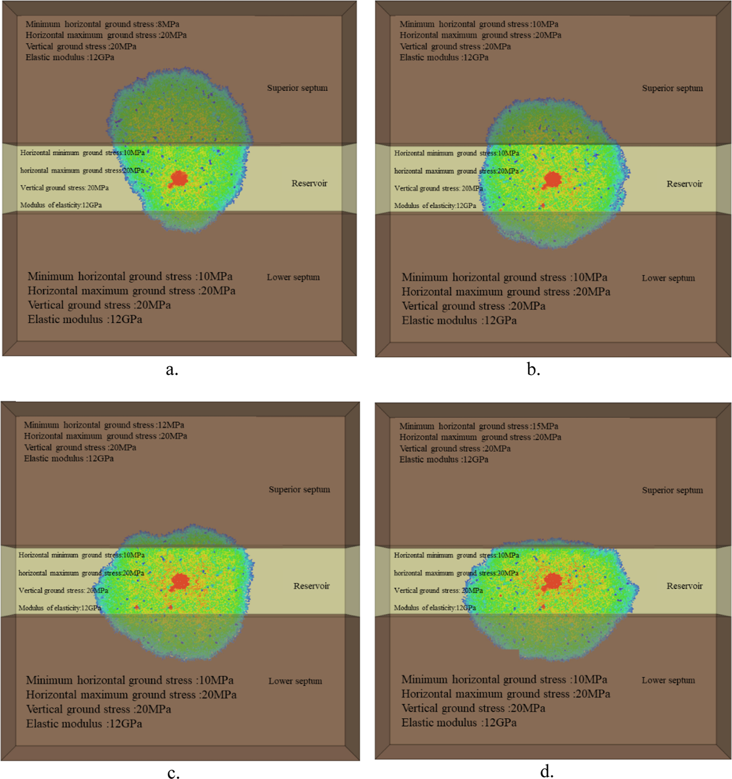
Influence of minimum horizontal ground stress difference of different reservoirs on joint height expansion. (a) The minimum horizontal ground stress of the upper compartment is 8 MPa. (b) The minimum horizontal ground stress of the upper compartment is 10 MPa. (c) The minimum horizontal ground stress of the upper compartment is 12 MPa. (d) The minimum horizontal ground stress of the upper compartment is 15 MPa.
Through quantitative analysis of the crack propagation morphology under different stress difference conditions, the control mechanism of stress difference on the crack penetration behavior can be obtained: When the crack spreads from the low stress area to the high stress area, additional stress resistance needs to be overcome, and this process requires more energy consumption. With the increase of stress difference between reservoir and interlayer, the pressure required to overcome this energy barrier also increases. When a certain threshold is reached, the fracture cannot continue to expand upward.
Through the parameter sensitivity analysis of the system, the critical conditions for fracture penetration are quantified, as shown in Figure 6: When the minimum horizontal ground stress difference between layers is greater than 7 MPa, vertical fracture propagation will be effectively inhibited. When the ratio of elastic modulus between layers is less than 0.5, the fracture height propagation is also significantly limited.
FIGURE 6

The impact relationship between the minimum horizontal stress difference and elastic modulus difference of the separator layer and reservoir layer on the critical conditions for crack penetration.
3.3 Effect of elastic modulus difference between interlayer and reservoir on fracture height
The impact of the elastic modulus difference between the mudstone interlayer and the sandstone reservoir on fracture height was investigated through numerical simulation. The results show that the difference of elastic modulus between mudstone interlayer and sandstone reservoir has significant influence on the hydraulic fracture height. The experimental results show that the mudstone interlayer has obvious limiting effect on fracture height. With the decrease of the elastic modulus of mudstone interlayer, the width of hydraulic fracture increases, and the fracture height decreases under the same fluid injection condition. In addition, the toughness characteristics of mudstone make it difficult to form a high stress concentration area at the tip of hydraulic fracture, which increases the difficulty of fracture initiation and extension.
Figure 7 quantitatively shows the mechanism of sandstone-mudstone modulus difference affecting fracture height. When the elastic modulus of the mudstone interlayer is 11 GPa lower than that of the sandstone reservoir (Figure 7a), the hydraulic fracture propagates vertically in the sandstone reservoir, but after entering the mudstone interlayer, the propagation is significantly inhibited, showing the characteristics of increasing width and limiting height. When the difference of elastic modulus decreases to 6 GPa (Figure 7b), the crack height increases correspondingly, indicating that the difference of elastic modulus is negatively correlated with the crack height.
FIGURE 7

Influence of sandstone-mudstone modulus difference on fracture height. (a) The elastic modulus of mudstone interlayer is 11GPa lower than that of sandstone reservoir. (b) The elastic modulus of mudstone interlayer is 6 GPa lower than that of sandstone reservoir.
In addition, the difference of minimum horizontal principal stress between mudstone interlayer and sandstone reservoir also has a key influence on fracture height. Figure 8 shows this regulatory effect: When the minimum horizontal principal stress of the mudstone interlayer is 4 MPa lower than that of the sandstone reservoir (Figure 8a), the fracture propagation resistance in the mudstone interlayer is small and the fracture height is larger. However, when the stress difference is reversed to a higher value of 4 MPa (Figure 8b), the crack height decreases significantly. This reveals the positive correlation between the difference of ground stress and fracture height, and provides an important theoretical basis for reservoir reconstruction design.
FIGURE 8

Influence of difference of ground stress between sandstone and mudstone on joint height. (a) The minimum horizontal principal stress of the mudstone interval is 4 MPa lower than that of the sandstone reservoir. (b) The minimum horizontal principal stress of the mudstone interlayer is 4 MPa higher than that of the sandstone reservoir.
3.4 Fracturing fluid parameters optimization
To explore the effects of fracturing fluid parameters on fracture penetration, numerical simulations were conducted based on the model parameters described in the preceding sections to investigate the influence of different fracturing fluid parameters on fracture penetration. The results show that the viscosity of fracturing fluid and the flow rate are the key parameters that affect the penetration ability of fractures. The high viscosity fracturing fluid significantly enhances the ability to penetrate the interlayer interface, and the injection strategy of “high viscosity leading and low viscosity following” can effectively achieve the dual goals of main fracture expansion and weak interlayer opening.
Figure 9 shows the mechanism by which fracturing fluid viscosity affects fracture penetration. When the viscosity is 5 mPa·s, the low-viscosity fracturing fluid promotes the expansion of the main fracture, but the opening effect of the weak surface between layers is not good. When the viscosity increased to 20 mPa·s, the ability of high-viscosity fracturing fluid to penetrate the interlayer interface was significantly improved, and both the main fracture and the weak interlayer were well opened. By using the compound injection scheme of 20 mPa·s followed by 5 mPa·s, the cooperative optimization of the expansion of the main seam and the opening of the weak surface between the layers was realized.
FIGURE 9

Influence of viscosity on fracture penetration. (a) The viscosity is 5 mPa∙s. (b) The viscosity is 20 mPa∙s. (c) The viscosity is 20 mPa∙s + 5 mPa∙s.
At the same time, fracturing fluid injection rate plays a significant role in regulating fracture height extension distance. The experimental results show that with the injection displacement increasing from 3.0 mL/min to 7.0 mL/min, the longitudinal penetration height of hydraulic fracture shows an obvious increasing trend. Figure 10 quantitatively describes the variation law of crack height expansion distance under different displacement: When the displacement is 3.0 mL/min, crack longitudinal expansion is significantly inhibited. When the displacement was increased to 5.0 mL/min, the expansion of seam height was improved. When the displacement reaches 7.0 mL/min, the fracture longitudinal extension effect is most significant. It is worth noting that with the increase of injection displacement, the fracture extension pressure gradually increases, especially when the artificial fracture extends to the upper and lower mudstone layers, the extension pressure increases sharply. When the injection displacement increases from 3.0 mL/min to 7.0 mL/min, the fracture extension pressure in the interlayer increases by about 10 MPa.
FIGURE 10

Expansion distance of fracture height under different fracturing fluid displacement.
Under the condition of displacement of 6 m3/min, the longitudinal penetration of seam height is significantly inhibited. Figure 11 shows the fracture propagation patterns at different times under this displacement: fractures start in the sandstone layer and begin to spread to the mudstone layer in 30 s; The fracture propagation height in mudstone layer is limited at 110 s. At 180 s, the fracture propagation in the mudstone layer is completely blocked, and the fracture height propagation stops. This is mainly due to the fact that when hydraulic fractures spread from sandstone to mudstone reservoir, the lower elastic modulus of mudstone leads to the increase of fracture width, reduces the stress concentration of crack tip, and hinders the further extension of fractures.
FIGURE 11

Fracture growth morphology at different time conditions with a displacement of 6 m3/min. (a) Fracture expansion pattern in 30 s. (b) Fracture expansion pattern in 110 s. (c) Fracture expansion pattern in 180 s.
Figure 12 Systematically compares the fracture propagation patterns under different discharge rates: when the discharge rate is 6 m3/min, fracture propagation is blocked in mudstone layer; When the displacement increased to 8 m3/min and 9 m3/min, the seam height expansion gradually increased but did not fully penetrate the layer. When the displacement reaches 10 m3/min, the fracture can completely penetrate the layer, but the fracture length decreases significantly, indicating that there is a critical relationship between the displacement and the penetration ability.
FIGURE 12

Fracture propagation patterns under different displacement. (a) The displacement is 6 m3/min. (b) The displacement is 8 m3/min. (c) The displacement is 9 m3/min. (d) The displacement is 10 m3/min.
In summary, high viscosity fracturing fluid and high injection rate are conducive to hydraulic fracture penetration of the interlayer interface. The compound injection strategy of “high viscosity leading and low viscosity following” can take into account the dual needs of main seam expansion and weak surface opening between layers. With the increase of injection displacement, the fracture extension pressure and longitudinal expansion height both increase, but the tradeoff between displacement and fracture length should be paid attention to.
4 Fracturing process optimization and reservoir expansion process recommendation
Based on the results of 3D discrete lattice numerical simulation and mechanism research, this study systematically constructs the hydraulic fracturing process optimization scheme according to the characteristics of sand and mudstone thin interlayer reservoir.
(1) According to the criteria for effective fracture penetration, the minimum horizontal stress difference between layers should be greater than 7 MPa and the elastic modulus ratio (interlayer/reservoir) should be less than 0.5. The corresponding optimized construction parameters suggest that the injection rate should not be lower than 8 m3/min and the fracturing fluid viscosity should not be lower than 20 mPa·s to enhance the fracture penetration capability.
(2) The fluid system design employs a composite injection strategy of “high-viscosity leading and low-viscosity following,” which means using high-viscosity fluid to initiate the fracture and then switching to low-viscosity fluid to activate the weak interlayer interfaces.
(3) The proppant combination is optimized to 30% ceramic powder (70–140 mesh), 60% medium-grain ceramic beads (40–70 mesh), and 10% large-grain ceramic beads (30–50 mesh) to achieve multi-scale fracture saturation packing.
(4) In response to varying geological conditions, this study has further analyzed the adaptability of the fracturing process. When the interlayer elastic modulus is lower than 6000 MPa, it is recommended to employ high-viscosity fracturing fluid (>20 mPa·s) to compensate for the loss of fracture width and suppress the phenomenon of limited fracture height. Conversely, when the stress difference between the reservoir and the interlayer is less than 5 MPa, low-viscosity fluid (10 mPa·s) should be prioritized to activate the weak interfaces between layers and construct a complex fracture network system.
(5) The economic analysis indicates that although the fracture penetration effect is most pronounced when the injection rate exceeds 10 m3/min, it is necessary to balance the construction costs with the limitations of fracture length. After comprehensive consideration, it is recommended to control the injection rate within the range of 8–10 m3/min to achieve the optimal balance between technical effectiveness and economic benefits. The optimal balance between technical effect and economic benefit can be achieved by controlling the displacement, thus reducing the cost in the case of enhanced oil recovery
5 Conclusion
(1) The three-dimensional discrete lattice method demonstrates high precision and reliability in simulating the extension of hydraulic fractures in thin interbedded sandstone and mudstone reservoirs, accurately capturing the stress concentration and energy release processes near the fracture tips, providing a reliable numerical tool for fracturing design.
(2) The ratio of elastic modulus between the storage layer and the interlayer is a key parameter controlling the vertical extension of fractures. When the elastic modulus ratio of the upper interlayer to the storage layer is less than 0.5, the vertical extension of fractures is significantly inhibited; when the ratio is greater than 1, the vertical extension of fractures is promoted.
(3) The minimum horizontal stress difference between layers is a decisive factor for fracture penetration. When the minimum horizontal stress difference between the storage layer and the interlayer is greater than 7 MPa, the vertical extension of fractures will be effectively inhibited.
(4) High-viscosity fracturing fluid (≥20 mPa·s) and high injection rate (≥8 m3/min) significantly enhance the ability of fractures to penetrate interlayer interfaces. The composite injection strategy of “high-viscosity leading and low-viscosity following” can achieve the synergistic optimization of main fracture extension and the initiation of weak interlayer interfaces.
Although this study has made some achievements, there are still many problems worth further research in the field of hydraulic fracturing of sand-mudstone thin interbedded reservoirs:
(1) Combining microseismic monitoring with discrete fracture network (DFN) models to quantify the guiding effect of natural fractures on the hydraulic fracture propagation path (e.g., construction parameters need to be adjusted when the fracture deflection Angle is > 30°), a multi-field coupling prediction model is established to optimize the complex fracture network design.
(2) For heterogeneous reservoir characteristics, develop viscosity adaptive adjustment fracturing fluid (such as pH response type), whose energy storage modulus should dynamically match the mechanical differences between layers to enhance the efficiency of penetration and reduce the risk of filtration.
(3) Deploy distributed optical fiber sensing (DAS/DTS) and dynamic productivity inversion in the target block, build a frake-productivity mapping database, and drive parameter iterative optimization to reduce the target single well production error rate.
Statements
Data availability statement
The original contributions presented in the study are included in the article/supplementary material, further inquiries can be directed to the corresponding author.
Author contributions
DS: Writing – review and editing. FX: Writing – original draft. LM: Investigation, Writing – review and editing. LL: Formal Analysis, Writing – review and editing. CH: Validation, Writing – review and editing.
Funding
The author(s) declare that no financial support was received for the research and/or publication of this article.
Conflict of interest
Author(s) DZ, FX, LM, LL, and CH were employed by Zhanjiang Branch of CNOOC (China) Co., LTD.
Generative AI statement
The author(s) declare that no Gen AI was used in the creation of this manuscript.
Publisher’s note
All claims expressed in this article are solely those of the authors and do not necessarily represent those of their affiliated organizations, or those of the publisher, the editors and the reviewers. Any product that may be evaluated in this article, or claim that may be made by its manufacturer, is not guaranteed or endorsed by the publisher.
References
1
Bakhshi E. Rasouli V. Ghorbani A. Fatehi Marji M. Damjanac B. Wan X. (2019). Latticenumerical simulations of lab-scale hydraulic fracture andnatural interface interaction. Rock Mech. Rock Eng.52 (5), 1315–1337. 10.1007/s00603-018-1671-2
2
Cheng Z. Ai C. Zhang J. Yan M. Tao F. Bai M. (2022). Influence of cementing natural fractures on fracture extension law of hydraulic fracturing. Xinjiang Pet. Geol.43 (04), 433–439. 10.7657/XJPG20220408
3
Cundall P. (2011). “Lattice method for modeling brittle, jointedrock,” in 2nd International FLAC/DEM Symposium oncontinuum and distinct element numerical modeling ingeo-mechanics. Melbourne, Australia.
4
Fan T. Zhang G. (2014). Effects of injection rate and fracturing fluid viscosity on hydraulic fracture morphology of coal seam. J. China Univ. Petroleum Ed. Nat. Sci.38 (04), 117–123.
5
Fan Y. Mei W. Li L. Sun Z. An Q. Yang Q. et al (2023). Research on fracture propagation characteristics of thin interbedded tight sandstone by hydraulic fracturing. Coal Geol. Explor.51 (07), 61–71. 10.12363/issn.1001-1986.22.10.0788
6
Guo T. Tang S. Liu S. Liu X. Zhang W. Qu G. (2020). Numerical simulation of hydraulic fracturing of hot dry rock under thermal stress. Eng. Fract. Mech.240, 107350. 10.1016/j.engfracmech.2020.107350
7
Huang Z. Li G. Yang R. Li G. (2022). Current situation and trend of development of coalbed methane development technology in China. J. coal47 (9), 3212–3238. 10.13225/j.carol.carrollnki.JCCS.SS22.0669
8
Li Q. Wu J. Li Q. Wang F. Cheng Y. (2025). Sediment instability caused by gas production from hydrate-bearing sediment in Northern South China Sea by horizontal wellbore: sensitivity analysis. Nat. Resour. Res.2025. 10.1007/s11053-025-10478-x
9
Liu X. Sun Y. Guo T. Rabiei M. Qu Z. Hou J. (2022). Numerical simulations of hydraulic fracturing in methane hydrate reservoirs based on the coupled thermo-hydrologic-mechanical-damage (THMD) model. Energy238, 122054. 10.1016/j.energy.2021.122054
10
Liu Z. Chen M. Jin Y. Lu Y. Hou B. (2014). Influence of mud interlayer on integrated fracturing of super-thick sand-mud interbed reservoir. Sci. Technol. Eng.14 (09), 34–38.
11
Lu P. Yang C. Liu W. Xu M. Xue L. (2022). Shale gas fracturing technology research progress. J. fine Petrochem. industry Prog.23 (02), 34–37. 10.13534/j.cnki.32-1601/te.2022.02.008
12
Lu Z. Pan L. Hao L. Zou N. Zou Z. (2023). Numerical simulation of influencing factors of fracture propagation in sand-mudstone interbed hydraulic fracturing. Xinjiang Pet. Geol.44 (06), 729–738. 10.7657/XJPG20230612
13
Pan R. (2021). Study on fracture characteristics of thin interbed rock and its application in hydraulic fracturing. Beijing: China university of petroleum. 10.27643/dc.nki.Gsybu.2021.000028
14
Pan R. Zhang G. (2018). Layered rock fracture energy anisotropy of hydraulic fracture extension path impact study. J. rock Mech. Eng.5 (10), 2309–2318. 10.13722/j.carol.carroll.nki.jrme.2018.0461
15
Qin M. Yang D. (2023). Numerical investigation of hydraulic fracture height growth in layered rock based on peridynamics. Theor. Appl. Fract. Mech.125, 103885. 10.1016/j.tafmec.2023.103885
16
Xu F. Yan X. Lin Z. Li S. Xiong X. Yan D. et al (2022). Research progress and development direction of key technologies for efficient CBM development in China. Coal Geol. Explor.50 (03), 1–14.
17
Yin J. Guo J. Zeng F. (2012). Research and application of low permeability thin interbed fracturing technology. Nat. Gas Oil30 (06), 52–54+84+3.
18
Zhang B. Guo T. Qu Z. Wang J. Chen M. Liu X. (2023). Numerical simulation of fracture propagation and production performance in a fractured geothermal reservoir using a 2D FEM-based THMD coupling model. Energy273, 127175. 10.1016/j.energy.2023.127175
19
Zhang F. Dontsov E. (2018). Modeling hydraulic fracture propagation and proppant transport in a two-layer formation with stress drop. Eng. Fract. Mech.199, 705–720. 10.1016/j.engfracmech.2018.07.008
20
Zhang J. Guan Y. Chen J. Dan Z. Gao F. Ji G. (2021). Shale gas fracturing technology progress and development. J. energy Environ. Prot. lancet (10), 102–109. 10.19389/j.cnki.1003-0506.2021.10.019
21
Zhang K. Tang M. Du X. Pan R. Nie Y. Wang X. (2017). Experimental study on influencing factors of joint height expansion in dense thin interlayer. Sci. Technol. Eng.17 (22), 197–203.
22
Zhao K. Zhang Z. Li W. Wang X. Yi K. Sun Z. (2021). Three-dimensional propagation of hydraulic fracture in drilling initiation based on XSite. Chin. J. Geotechnical Eng.43 (08), 1483–1491. 10.11779/CJGE202108013
23
Zhao K. K. Stead D. Kang H. P. Gao F. Donati D. (2021). Three-dimensionalsimulation of hydraulic fracture propagation height in layeredformations. Environ. Earth Sci.80 (12), 435. 10.1007/s12665-021-09728-x
24
Zhou X. Zhang S. Ma X. Liu M. (2015). Research on high technology of hydraulic fracturing fracture control in thin differential layer. J. Shaanxi Univ. Sci. Technol. Nat. Sci. Ed.33 (04), 94–99.
25
Zhu W. Chenhui W. Jun T. Yang T. Tang C. (2009). The coupled thermo-fluid-force model in rock damage process and its application. Rock Soil Mech., 51–57. 10.16285/j.rsm.2009.12.017
Summary
Keywords
thin-interbedded sandstone-shale, hydraulic fracturing, fracture propagation, 3D discrete lattice method, fracturing process optimization
Citation
Sun D, Xu F, Ma L, Li L and Han C (2025) Mechanism of hydraulic fracture propagation and fracturing process optimization in thin-interbedded sandstone-shale reservoirs based on 3D discrete lattice method. Front. Earth Sci. 13:1602646. doi: 10.3389/feart.2025.1602646
Received
30 March 2025
Accepted
22 April 2025
Published
23 May 2025
Volume
13 - 2025
Edited by
Qingchao Li, Henan Polytechnic University, China
Reviewed by
Tiankui Guo, China University of Petroleum, China
Liangbin Dou, Xi’an Shiyou University, China
Fucheng Deng, Yangtze University, China
Updates
Copyright
© 2025 Sun, Xu, Ma, Li and Han.
This is an open-access article distributed under the terms of the Creative Commons Attribution License (CC BY). The use, distribution or reproduction in other forums is permitted, provided the original author(s) and the copyright owner(s) are credited and that the original publication in this journal is cited, in accordance with accepted academic practice. No use, distribution or reproduction is permitted which does not comply with these terms.
*Correspondence: Fabin Xu, 896948175@qq.com
Disclaimer
All claims expressed in this article are solely those of the authors and do not necessarily represent those of their affiliated organizations, or those of the publisher, the editors and the reviewers. Any product that may be evaluated in this article or claim that may be made by its manufacturer is not guaranteed or endorsed by the publisher.