 Guangyi Li1
 Qi Ma
Qi Ma- 1Chengzhuang Mine, Jinneng Holdings Equipment Manufacturing Group, Jincheng, China
- 2Hebei State Key Laboratory of Mine Disaster Prevention, Langfang, China
- 3School of Safety Engineering, North China Institute of Science and Technology, Langfang, China
- 4School of Mines, China University of Mining and Technology, Xuzhou, Jiangsu, China
The width of the coal pillar is a key factor in the success of the gob-side entry driving (GED) technique. This paper, based on the 4,317 working face at Chengzhuang Coal Mine, reveals the stability mechanism of roadway surrounding rock during GED with coal pillars of different widths. Firstly, a main roof failure mechanical model was established using the “internal and external stress field” theory, and the range of the internal stress field was calculated to be 13.6–15.2 m, with the optimal coal pillar width being 10 m. Then, a FLAC3D numerical model was developed and calibrated. Through simulation, the stress and plastic zone evolution characteristics of coal pillars with widths of 5 m, 10 m, 15 m, and 20 m were compared. The results show that a 5 m coal pillar has weak bearing capacity, is prone to plastic failure, and the surrounding rock stability is poor. A 10 m coal pillar exhibits a more uniform stress distribution, smaller plastic zone, and maintains a certain elastic region, with good bearing capacity and no significant stress concentration. It is the optimal design width, offering strong economic and safety advantages. In contrast, 15 m and 20 m coal pillars show significant stress concentration, threatening coal pillar stability and causing resource waste. Finally, a combined control technique of “hydraulic fracturing roof cutting + roof anchor cable + rib anchor cable” with specific parameters was proposed and successfully applied in the 4,317 tailgate. Field monitoring results showed that the surrounding rock deformation stabilized after 55 days, with a maximum deformation of 151 mm, indicating good control effectiveness.
1 Introduction
With the rapid advancement of intelligent coal mine construction in China, the coal production model is undergoing a profound transformation (Chen et al., 2024a; Liu et al., 2023), shifting from a traditional extensive approach to a modern, intensive, and efficient model (Chen et al., 2025; Lu et al., 2024; Yin et al., 2024a). In this context, the small coal pillar GED technology, as a significant method to optimize coal resource recovery in mines, has garnered increasing attention and emphasis within the coal industry (Yin et al., 2024b; Zhang et al., 2022; Jia et al., 2022; Zhang et al., 2020).
GED refers to the technique where, after the recovery of the upper section’s working face is completed, the mining roadway of the current section advances along the edge of the mined-out area of the upper section, leaving a narrow coal pillar to support the roadway (Liu and Han, 2021; Xie et al., 2024; Liu et al., 2022; Bertuzzi et al., 2016; Das et al., 2019). However, this technique faces complexities in the design of coal pillar width (Xue, 2024; Chen, 2021; Li et al., 2023; Jaiswal and Shrivastva, 2009). When the coal pillar is too narrow, it is highly susceptible to mining stress (Ren et al., 2025; Han et al., 2025), leading to severe roof subsidence, increased horizontal displacement of the coal pillar, and widespread plastic failure, ultimately resulting in the loss of load-bearing capacity (Chang et al., 2022; Guo et al., 2023; Shan et al., 2024). Conversely, if the coal pillar is too wide, significant coal resource waste occurs, weakening economic benefits (Tan et al., 2022; Wang et al., 2020; Xu et al., 2024). Therefore, exploring the optimal width of protective coal pillars is crucial to enhancing the effectiveness of GED technology (He et al., 2023; Liu et al., 2021; Wang et al., 2024; Zhang et al., 2024).
In recent years, domestic and international scholars have achieved significant research results regarding the width of coal pillars in GED (Li et al., 2021; Han et al., 2022; Wang and Xie, 2022; Yang et al., 2023). Qi et al. (2016) utilized theoretical calculation methods to define the threshold range for the reasonable width of narrow coal pillars in GED, supported by numerical simulation analysis and field validation, to comprehensively determine the optimal width of narrow coal pillars in longwall mining GED. Li et al. (2012) further derived the mathematical expression for the internal stress field’s width, clarified the reasonable layout position for GED, and innovatively proposed a secondary support strategy for solid coal rib, constructing a theoretical framework for the asymmetric longwall GED surrounding rock control technology. Wang et al. (2021) established a mechanical model, combining orthogonal experimental design and range analysis methods, to systematically analyze multiple factors affecting the stability of surrounding rocks in GED, highlighting that the height and fracture position of the main roof are key factors influencing surrounding rock stability. Shi et al. (2020) integrated physical model experiments and numerical simulation techniques to explore the movement characteristics, failure mechanisms, and dynamic laws of crack evolution in the overlying rock layers during GED in thick coal seams. Ma et al. (2020) used a comprehensive methodology combining numerical simulation, field monitoring data, and theoretical analysis to define the reasonable width of coal pillars in GED. On this basis, they proposed a dual strategy of strengthening roof and coal rib support to effectively maintain the stability of GED. Zhang et al. (2021) employed controlled roof cutting techniques to manage the fracture location of the main roof, optimizing factors such as the roof cutting angle, depth, hole spacing, and layout, to study the mechanisms and surrounding rock control of the 6 m high mining face with narrow coal pillars. They found that combining roof cutting pressure relief and complementary support techniques can ensure the stability of surrounding rocks during both the advancing and retreating phases of GED with narrow coal pillars. These research outcomes provide a solid foundation for the widespread application of small coal pillar GED.
This paper focuses on the 4,317 tailgate as a case study. The research combines theoretical analysis, numerical simulations, and field experiments to investigate the dynamic evolution of internal and external stress fields in GED, determining the distribution range of the internal stress field. A comparative analysis of the stress and plastic zone characteristics of surrounding rock under different coal pillar widths is conducted to determine the optimal coal pillar width.
2 Engineering background
Currently, Chengzhuang Coal Mine is exploiting the 3# coal seam, with the 4,315 panel having been fully mined, and the 4,317 panel yet to be arranged. The layout of the working faces is shown in Figure 1. In the past, Chengzhuang Coal Mine has primarily utilized wide coal pillar mining, resulting in significant resource wastage. To improve coal resource recovery rates, the mine has decided to optimize the coal pillar width between the 4,315 and 4,317 panels, implementing GED.
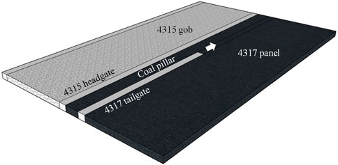
Figure 1. Working face layout.
The average thickness of the 3# coal seam is 4.0 m, with an average dip angle of 3° and a burial depth of approximately 400 m. The 4,317 tailgate is being driven along the floor of the 3# coal seam. As shown in Figure 2, The floor is composed of 6.4 m of sandy mudstone, the roof consists of 4.6 m of siltstone, and the main roof is made up of 10.5 m of sandstone.
The 4,317 tailgate has a rectangular cross-section, with a width of 5.0 m and a height of 3.5 m. The original support plan for the 4,317 tailgate is shown in Figure 3. The roof support system consists of φ22 × 2,400 mm bolts and φ22 × 5,300 mm anchor cables, with bolt spacing of 1,000 × 1,000 mm and anchor cable spacing of 1,000 mm. The two ribs are supported by φ22 × 2,400 mm bolts, with spacing of 1,000 × 1,000 mm.
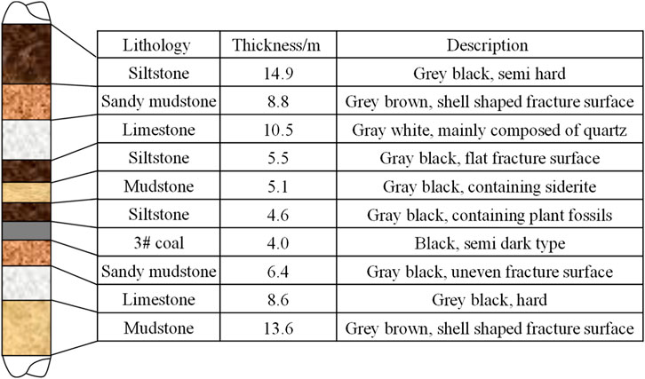
Figure 2. Borehole stratigraphy.
3 Distribution law of internal and external stress fields in GED
3.1 Evolution of internal and external stress fields
After the mining of the upper section’s working face is completed, the surrounding stress distribution undergoes significant changes, with the stress gradually shifting toward the solid coal regions on both sides of the mined-out area (Jiang et al., 2021). During this process, the surrounding rock of the upper section undergoes deformation, and the coal wall displays diversified stress field distribution characteristics, as illustrated in Figure 4. Figures 4A–C show the distribution of stress fields at different stages, while Figure 2 illustrates the stress field state after the entry driving.
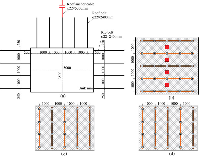
Figure 3. 4,317 tailgate support scheme. (a) Support section. (b) Top view of roof. (c) Side view of coal pillar rib. (d) Side view of solid coal rib.
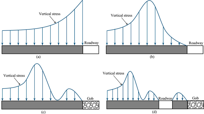
Figure 4. Evolution of support stress. (a) Single elastic distribution. (b) Plastic failure. (c) Differentiation of internal and external stress fields. (d) Distribution of stress field after excavation.
Figure 4A depicts the distribution of a purely elastic stress field. When the coal body surrounding the working face has not yet entered the plastic deformation stage, the stress concentration zone is mainly located at the edge of the coal wall, with the coal seam as a whole being in a state of elastic compression.
As mining progresses, Figure 4B reveals the appearance of plastic failure. When the elastic deformation of the main roof reaches its peak but has not yet fractured, the coal body at the edge of the mined-out area is in an ultimate bearing state, with its load-bearing capacity significantly reduced, and stability seriously threatened.
Further, Figure 4C depicts the differentiation of internal and external stress fields. When the main roof fractures within the solid coal, forming a distinct fracture line, the stress field is divided into two regions: the internal and external areas. The stress level at the fracture line significantly decreases, and the coal body at the edge of the solid coal is severely crushed, almost losing its load-bearing capacity entirely.
Finally, Figure 4D shows the stress field distribution after the entry driving. The excavation of the roadway causes the redistribution of support pressure within the lateral coal body. Due to the combined effects of the mined-out area and the GED, stress concentration occurs within the coal pillar on the side of the mined-out area. Meanwhile, the solid coal side remains divided into two stress fields by the fracture line of the main roof. In the internal stress field region, the coal body undergoes failure, strength decreases, mechanical properties weaken, and load-bearing capacity significantly declines, making it prone to spalling. Therefore, reinforcement support measures are needed to ensure the stability of the roadway.
3.2 Mechanical model
The location of the fracture in the main roof is indeed a complex issue, influenced by various geological and mining conditions, including mining height, depth, and the mechanical properties of the coal and rock strata. Based on the actual conditions of the 3# coal seam, since the coal seam and immediate roof are softer relative to the main roof, the main roof tends to fracture within the solid coal during the mining process.
When the main roof fractures on the inside of the coal wall, the arrangement of the gob-side entry becomes particularly crucial. As shown in Figure 5, there are three possible layout configurations, each corresponding to different stress environments and challenges for roadway stability.
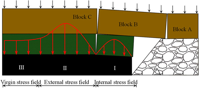
Figure 5. Model of main roof fracture in GED.
Configuration I: The roadway is located within the internal stress field, where the coal seam is generally in a pressure-relieved state, and the stress values are relatively low. Therefore, this configuration causes minimal changes in support pressure and is relatively easier to maintain stability. This is advantageous for roadway support and maintenance.
Configuration II: The roadway is located in the peak support pressure zone of the external stress field. In this configuration, the coal body on both sides of the roadway transitions from a three-directional stress state to a one-directional stress state, leading to significant damage to the surrounding rock and increasing the difficulty and cost of support. Moreover, this layout configuration makes it challenging to meet the safety and stability requirements for production.
Configuration III: The roadway is located in the virgin stress zone, which is the region with minimal stress and deformation. However, to achieve this layout, a larger coal pillar width must be left, which not only wastes valuable coal resources but may also have a detrimental impact on mining efficiency and economic benefits.
In conclusion, when choosing the layout configuration for a gob-side entry, multiple factors such as roadway stability, support costs, coal resource utilization, and mining efficiency need to be comprehensively considered. For the 3# coal seam, Configuration I might be an ideal choice, as it ensures roadway stability while reducing support costs and avoiding unnecessary coal resource waste.
According to the theory of “internal and external stress fields”, the expression for the supporting pressure σy at a distance x from the coal pillar in the internal stress field is given by:
Where: Gx is the stiffness of the coal at a distance x from the coal pillar, Pa. yx is the deformation of the coal at a distance x from the coal pillar, m. To simplify the analysis, we treat the distributions of Gx and yx as linear:
Where: G0 is the maximum coal stiffness in the internal stress field, Pa. y0 is the maximum deformation of the coal in the internal stress field, m. x1 is the distribution range of the internal stress field, m.
By substituting Equations 1, 2 together, we get:
From literature (Sun et al., 2023), we know:
Where: L is the length of the working face, m. C0 is the step distance of the initial pressure in the previous working face, m. hj is the thickness of the main roof layer, m. ρ is the density of the main roof, kN/m3. E is the Young’s modulus of coal, Pa. v is Poisson’s ratio. ξ is the influence coefficient.
From geometric relations, we get:
Where: hm is the thickness of the coal seam, m. hz is the thickness of the immediate roof, m. n is the swelling coefficient of the immediate roof. LB is the span of the suspended beam, m.
By substituting Equations 3–6, we obtain:
Based on the geological conditions of the 4,317 working face and laboratory test results, we know: ρ = 25 kN/m3, hj = 10.5 m, L = 200 m, C0 = 34.7–42.6 m, LB = 14.4–16.8 m, ξ = 0.8, v = 0.32, E = 7.85 GPa, hm = 4.0 m, hz = 4.6 m, n = 1.78. Substituting these parameters into Equation 7, the distribution range of the internal stress field is found to be between 13.6 m and 15.2 m.
3.3 Theoretical calculation of coal pillar width
According to the limit equilibrium theory (Chen et al., 2024b; Wang et al., 2023), the coal pillar width B satisfies the Equations 8–10:
Where: B is the coal pillar width, m. L1 is the width of the plastic zone on the gob side of the coal pillar, m. L2 is the width of the elastic core zone inside the coal pillar, m. L3 is the effective length of the bolt, taken as 1.4 m.
Where: m is the coal seam thickness, taken as 4.0 m. A is the side pressure coefficient, taken as 0.45. φ is the friction angle of the coal, taken as 29°. K is the stress concentration factor, taken as 2.5. ρ is the average unit weight of the overlying strata, taken as 25 kN/m3.H is the depth of the roadway, taken as 500 m. C is the cohesion of the coal, taken as 2.1 MPa pz is the support resistance of the bolt to the coal wall, taken as 0.12 MPa.
Based on these conditions, the estimated values are: L1 = 5.0 m, L2 = 3.2 m. Thus, the coal pillar width B = 9.6 m. In order to ensure that the anchor bolt anchoring section is within the stable coal body, the final coal pillar width is determined to be 10 m.
The theoretical calculation shows that with a coal pillar width of 10 m, the roadway is positioned within the internal stress field range of 13.6–15.2 m. The roadway will be in a low-stress environment, which is beneficial for roadway stability and maximizes coal resource utilization, yielding significant technical and economic benefits.
4 Stability of coal pillar in GED
4.1 Model establishment
A numerical model is established using FLAC3D, as shown in Figure 6. The model dimensions are 180 × 200 × 82 m. The displacements at the bottom and the four sides of the model are fixed. A vertical stress of 9.0 MPa is applied at the top of the model to simulate the overburden load, with a lateral pressure coefficient of 1.2. To accurately replicate the mechanical properties of the rock layers, the Double-yield model is used to simulate the gob area, the Strain-softening model is used to simulate the coal pillar, while the Mohr-Coulomb model is used to simulate the other rock layers. The mechanical parameters of the rock layers used in the model are listed in Table 1.
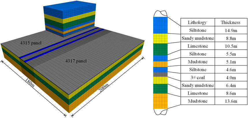
Figure 6. Numerical model.
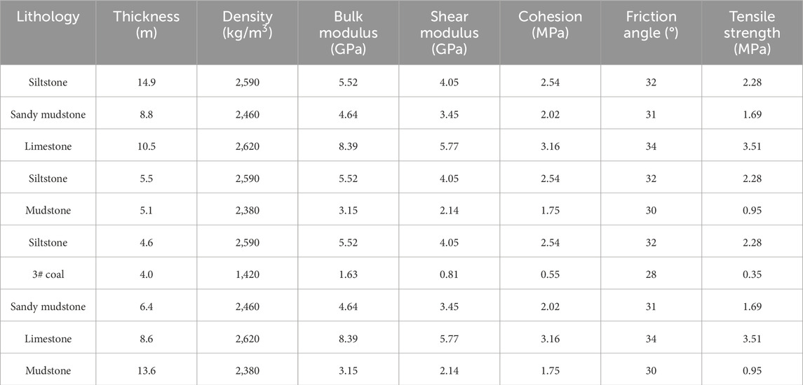
Table 1. Mechanical parameters of rock stratum.
The specific simulation process is divided into four steps:
Step 1: Build the model, add boundary conditions, apply the in situ stress, and run the model to achieve initial in situ stress equilibrium. Then, excavate the 4,315 headgate.
Step 2: Assign the Double-yield model to the rock stratum in the 4,315 gob to simulate the mining of the 4,315 working face.
Step 3: Set coal pillar widths to 5 m, 10 m, 15 m, and 20 m, and excavate the 4,317 tailgate. Assign the Strain-softening model to the coal pillar.
Step 4: Assign the Double-yield model to the rock stratum in the 4,317 gob to simulate the mining of the 4,317 working face.
4.2 Calibration of model
After the mining of the working face, the surrounding rock mass in the gob area gradually becomes compacted. During this process, the mechanical properties of the rock mass exhibit dynamic changes (Chen et al., 2024c). The Salamon theoretical model is used to describe the stress-strain relationship of the rock mass in the gob, and it is widely applied in engineering practice (Chen et al., 2024d; Chen et al., 2023).
The stress-strain relationship is given by the Equations 11–14 (Wang et al., 2024):
Where: σ is the vertical stress on the gob rock mass, MPa. εg is the strain of the gob rock mass. E0 is the initial modulus of the gob rock mass, GPa. bg is the swelling coefficient of the gob rock mass. εg max is the maximum strain of the gob rock mass. σc is the uniaxial compressive strength of the roof rock mass, MPa.
Based on laboratory tests, the average uniaxial compressive strength of the roof sandstone is 39.6 MPa, the swelling coefficient of the gob rock mass is 1.3, the maximum strain is 0.23, and the initial modulus is 63.69 GPa. The stress-strain relationship of the gob rock mass is shown in Table 2.
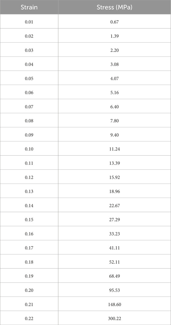
Table 2. Stress-strain relationship of Double-yield model.
In FLAC3D, a Double-yield model with a cell size of 1 m is established, with displacement fixed at the bottom and surrounding surfaces, and a vertical load of 10–5 m/step applied at the top (Xie et al., 2022). The calibration results are shown in Figure 7, where the Salamon model and the numerical simulation results are highly consistent. The parameters for the Double-yield model are listed in Table 3.
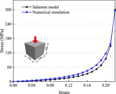
Figure 7. Model calibration results.

Table 3. The mechanical parameters of double-yield model.
To verify the rationality of the stress environment in the 4,315 gob, the Double-yield model is applied to the 4,315 gob, and the model is run until equilibrium is achieved. Measurement lines are arranged along the strike of the working face, and the results are shown in Figure 8. The stress in the 4,315 gob gradually recovers to the virgin stress, with the vertical stress recovering to 98.1% (9.32 MPa) of the virgin stress (9.5 MPa) at a distance of 70 m from the 4,315 headgate. This further validates the overall rationality of the model.
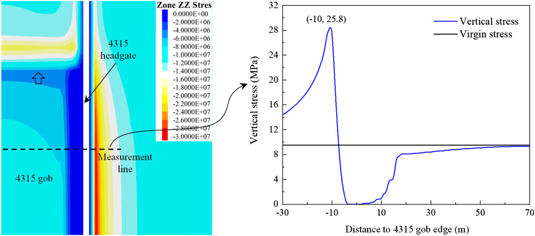
Figure 8. Gob stress.
The mechanical parameters selected for the coal pillar in the Strain-softening model are shown in Table 4. When the strain rate of the coal pillar reaches 1%, the cohesion decreases by 30% and the internal friction angle decreases by 8°.
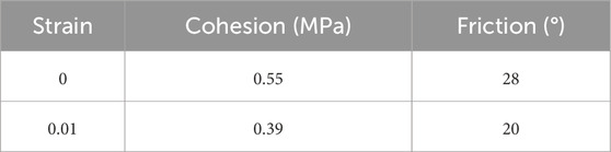
Table 4. The mechanical parameters of Strain-softening model.
4.3 During excavation period of the roadway
During the excavation of the 4,317 tailgate, the rock mass stress distribution is shown in Figure 9.
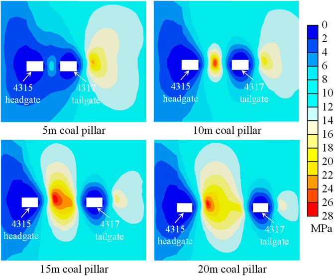
Figure 9. Stress distribution map.
When the coal pillar width is 5 m, the stress is primarily concentrated on the solid coal side. The internal stress of the coal pillar is significantly lower than the virgin stress, indicating that the coal pillar itself does not have sufficient load-bearing capacity. The low stress state inside the coal pillar reflects its inability to effectively bear the surrounding rock pressure, which may increase the instability of the surrounding rock mass.
As the coal pillar width increases to 10 m, a small area of stress concentration appears in the middle of the coal pillar. This indicates that the load-bearing capacity of the coal pillar begins gradually manifest.
Further increasing the coal pillar width to 15 m and 20 m results in a large area of stress concentration in the middle of the coal pillar. This shows that with the increase in coal pillar width, the pressure borne by the coal pillar also increases.
Stress curves along the centerline of the coal pillar are shown in Figure 10.
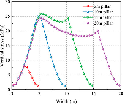
Figure 10. Stress curves.
When the coal pillar width increases from 5 m to 20 m, the vertical stress curve changes from a “single peak” to a “double peak” shape.
Single peak shape: when the coal pillar width is 5 m and 10 m, the vertical stress curve exhibits a single peak shape, with the maximum vertical stress at the centerline of the coal pillar. As the distance from the centerline increases, the vertical stress gradually decreases. When the coal pillar width is 5 m, the peak vertical stress at the centerline is smaller than the virgin stress, indicating that the coal pillar has undergone plastic failure and lost most of its load-bearing capacity. However, when the coal pillar width is 10 m, the peak vertical stress is greater than the virgin stress, suggesting that the coal pillar still possesses certain load-bearing capacity.
Double peak shape: when the coal pillar width increases to 15 m and 20 m, the vertical stress curve shows a double peak shape. In this case, the vertical stress at the centerline of the coal pillar is relatively small, and as the distance from the centerline increases, the vertical stress gradually increases. Two peak values appear near the coal pillar edges, with the “rear peak” being lower than the “front peak”. At this point, the vertical stress inside the coal pillar is generally greater than the virgin stress, indicating that the coal pillar has strong load-bearing capacity.
The distribution of the plastic zone during the excavation of the 4,317 tailgate is shown in Figure 11.
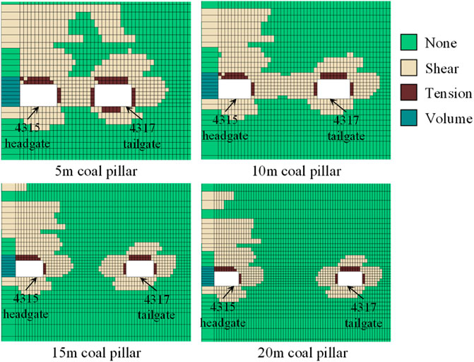
Figure 11. Plastic zone distribution.
When the coal pillar width is 5 m and 10 m, the plastic zone almost spans the entire coal pillar, indicating that the coal pillar has undergone plastic deformation at these sizes. When the coal pillar width is 5 m, the development of the plastic zone suggests that the strength of the coal pillar is insufficient to support its own weight, which could lead to overall instability. As the coal pillar width increases to 10 m, the plastic zone still occupies the entire area of the coal pillar, but the overall stability of the 10 m coal pillar is better than that of the 5 m coal pillar.
When the coal pillar width exceeds 10 m, the distribution of the plastic zone begins to change significantly, especially in the middle of the coal pillar. Specifically, when the coal pillar width is 15 m and 20 m, a complete zone gradually forms in the middle of the coal pillar. As the coal pillar width increases further, the range of the complete zone significantly expands. For the 15 m coal pillar, the width of the complete zone is approximately 4.5 m, while for the 20 m coal pillar, the width increases to 10.5 m.
4.4 During mining period of the working face
At the measurement station in the middle of the model (y = 100 m), the symbol “-” indicates that the working face has not yet passed the station, and the symbol “+” indicates that the working face has passed the station. The evolution of the stress distribution during the mining of the 4,317 working face is shown in Figure 12.
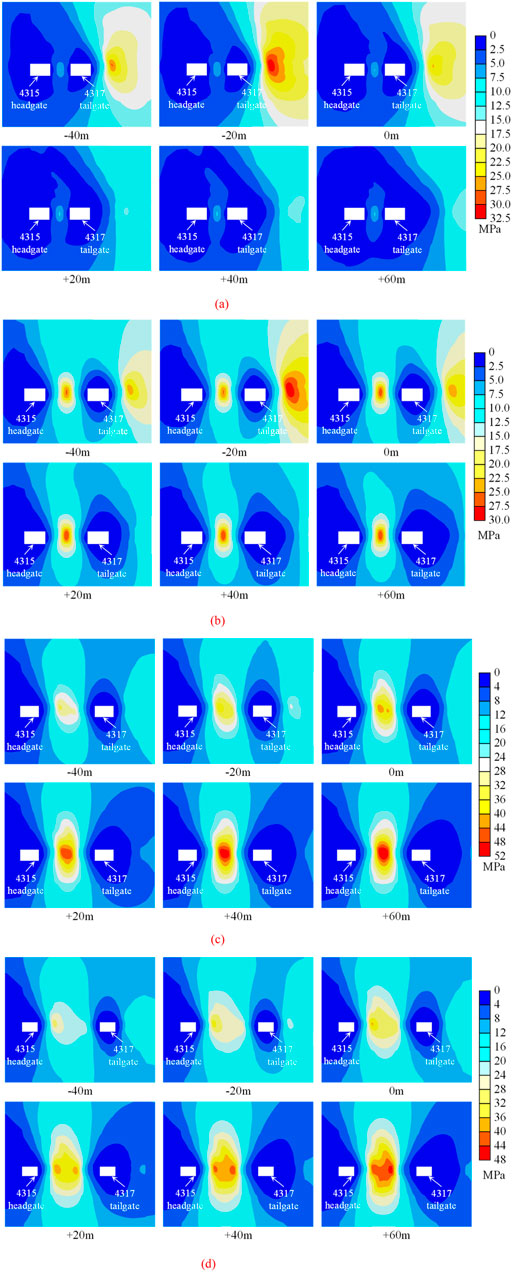
Figure 12. Stress distribution evolution. (a) 5 m coal pillar. (b) 10 m coal pillar. (c) 15 m coal pillar. (d) 20 m coal pillar.
As the working face advances, the range of stress concentration inside the coal pillar gradually increases. However, the degree of increase in stress concentration varies significantly for coal pillars of different widths. Specifically:
5 m coal pillar: during mining, there is almost no noticeable stress concentration inside the coal pillar. Due to the narrow width of the coal pillar and its weak load-bearing capacity, the effect of mining on the coal pillar’s internal stress is limited, with no significant areas of stress concentration.
10 m coal pillar: compared to the 5 m coal pillar, the stress concentration in the 10 m coal pillar increases slightly, but the growth is relatively small, and the stress concentration area remains elliptical in shape. This indicates that although the coal pillar width has increased, the stress concentration inside the pillar remains limited and is primarily concentrated in the center, without large-scale stress expansion.
15 m and 20 m coal pillars: as the coal pillar width further increases, the range of stress concentration expands significantly. During mining, the stress concentration area inside the coal pillar gradually changes from the initial yellow region to the red region, and the extent of the red region increases as the working face advances. This indicates that in the 15 m and 20 m wide coal pillars, the effect of mining on the internal stress becomes more pronounced, resulting in larger areas of stress concentration. As the working face moves towards the measurement station, the stress concentration inside the coal pillar becomes more noticeable.
Stress evolution curves along the centerline of the coal pillar are shown in Figure 13.
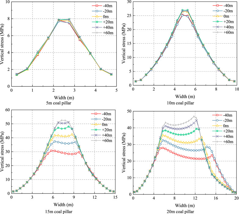
Figure 13. Stress evolution curves.
When the coal pillar width is 5 m, the vertical stress curve during mining remains essentially consistent with the excavation phase, showing no significant changes. This indicates that for a 5 m coal pillar, the stress distribution remains stable, and the effect of mining on the coal pillar’s stress state is minimal, with no notable areas of stress concentration or significant changes. This situation likely arises because the narrow coal pillar has a higher risk of overall instability, resulting in a more consistent stress state during mining.
When the coal pillar width is 10 m, the vertical stress curve remains stable during the mining period. The stress peak shows a tendency to rise and then decrease before stabilizing. The increase and decrease of the stress peak are relatively small, stabilizing around 26 MPa. This suggests that the internal stress distribution of the 10 m coal pillar is reasonable, and its load-bearing capacity remains stable during mining. There is no excessive stress concentration or damage. Therefore, the 10 m wide coal pillar represents an ideal load-bearing state, maintaining stability and avoiding excessive damage during the mining process.
When the coal pillar width is 15 m, the vertical stress curve gradually evolves from a “double peak” shape to a “single peak” shape. As working face advances, the mining effect becomes more apparent, and the stress peak inside the coal pillar increases, reaching 52.5 MPa at −60 m. This indicates that as the coal pillar width increases to 15 m, the mining effect during mining has a more significant impact on the coal pillar’s stress distribution, especially in the middle, leading to an increasing concentration of stress, which threatens the pillar’s stability.
When the coal pillar width is 20 m, the vertical stress curve evolves from a “left-high, right-low” double peak shape to a “left-low, right-high” double peak shape. The stress peaks show an overall increasing trend, reaching 46.9 MPa at −60 m. This change reflects that as the coal pillar width increases, the stress concentration areas shift, and the overall stress peaks rise. The internal stress state of the coal pillar becomes more unstable, and its load-bearing capacity may begin to weaken, particularly in specific areas during the mining process.
The evolution of the plastic zone during the mining of the 4,317 working face is shown in Figure 14.
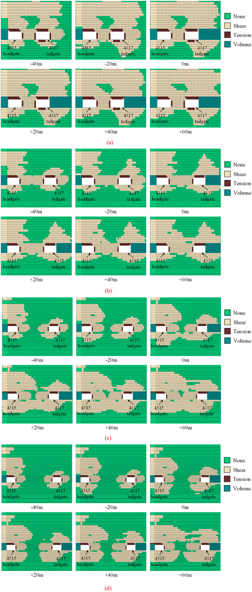
Figure 14. Plastic zone evolution. (a) 5 m coal pillar. (b) 10 m coal pillar. (c) 15 m coal pillar. (d) 20 m coal pillar.
During mining, the 5 m and 10 m coal pillars remain in a plastic state, with no noticeable elastic zones. In the 5 m coal pillar, the plastic zone nearly spans the entire pillar, and both the roof and floor plates are in a plastic failure zone, resulting in a significant decrease in load-bearing capacity. Compared to the 5 m coal pillar, the plastic zone in the 10 m pillar is smaller, especially in the roof and floor plate areas, where the plastic range is noticeably reduced, indicating that increasing the coal pillar width helps limit the extent of plastic failure.
As the coal pillar width increases, the plastic zone in the 15 m coal pillar gradually expands and eventually spans the entire coal pillar. However, although the plastic zone extends throughout the coal pillar, a small elastic region remains in the middle.
In the 20 m coal pillar, the middle area maintains a certain range of elastic zone. Particularly at −60 m, the elastic zone width remains 6 m. This indicates that as the coal pillar width increases, the elastic region grows.
4.5 Discussion on coal pillar width
After analyzing the stress and plastic zone evolution during the excavation and mining processes of coal pillars with different widths, the following conclusions can be drawn:
When the coal pillar width is 5 m, the vertical stress peak (7.9 MPa) during excavation is less than the virgin stress, indicating plastic failure and a significant loss of load-bearing capacity. The plastic zone spans nearly the entire pillar, including the roof and floor, with no remaining elastic core. During mining, the vertical stress curve remains essentially unchanged, and the stress concentration is negligible, confirming the pillar’s inability to sustain additional load. This results in complete plastic failure, posing a high risk of instability, which severely compromises roadway safety.
When the coal pillar width is increased to 10 m, the peak vertical stress during excavation rises to 26 MPa, exceeding the virgin stress, and an elastic region appears in the core of the pillar. During mining, the stress peak fluctuates slightly but remains stable around 26 MPa, indicating a reasonable and consistent internal stress distribution. The plastic zone becomes smaller, particularly at the roof and floor interfaces, where failure zones are significantly reduced. These results suggest that the 10 m coal pillar maintains a balanced stress state, with adequate load-bearing capacity and effective confinement, making it the most stable and efficient design among the simulated cases.
When the coal pillar width reaches 15 m, the vertical stress curve during mining evolves from a double-peak to a single-peak shape. The peak stress increases significantly, reaching 52.5 MPa at −60 m, which is more than the virgin stress, indicating a strong mining influence. Although a small elastic zone remains in the pillar center during excavation, it becomes compressed as mining progresses, and the plastic zone eventually spans nearly the entire pillar. While the load-bearing capacity increases, the high degree of stress concentration raises the risk of local failure, especially in the center of the pillar. Therefore, although the 15 m coal pillar supports a greater load, it may be susceptible to localized overstressing and instability under continuous mining influence.
At a coal pillar width of 20 m, the vertical stress peaks shift during mining, showing a transformation from a “left-high, right-low” to a “left-low, right-high” double-peak shape, with a maximum stress of 46.9 MPa at −60 m. An elastic zone of approximately 6 m in width remains in the middle of the pillar, indicating improved structural integrity. However, the wider pillar also results in greater stress redistribution and more extensive stress concentration zones, particularly near the edges. Despite the increased load-bearing performance, the plastic zone expands during mining, and the marginal gain in stability is offset by substantial resource loss due to excessive coal retention. This makes the 20 m pillar an economically inefficient option, offering diminishing returns in exchange for greater material wastage.
In conclusion, a 10 m coal pillar is the optimal choice, as it strikes a balance between ensuring sufficient load-bearing capacity and avoiding excessive failure or resource waste. This width ensures that the pillar remains in a yield state, effectively supports the overlying strata’s pressure, conserves resources, and maintains the mine’s economic and operational sustainability. Therefore, a 10 m coal pillar offers ideal performance during extraction, ensuring both safety and mining efficiency, making it the most rational and optimized design solution.
5 Industrial experiment
5.1 Control strategy
Based on the above theoretical analysis and simulation results, and considering the site conditions at Chengzhuang Coal Mine, a roadway surrounding rock control system was developed, focusing on the “hydraulic fracturing roof cutting + roof anchor cable + rib anchor cable” approach, as shown in Figure 15.
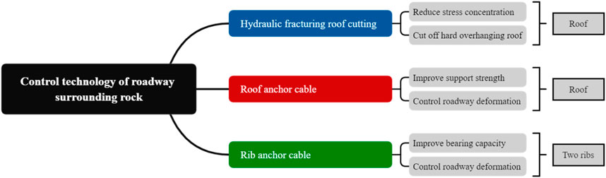
Figure 15. Control strategy.
5.2 Control scheme
According to the characteristics of the roof above the 3# coal seam, limestone (10.5 m) is the primary factor contributing to significant deformation in the gob-side entry. To ensure the stability of the 4,317 tailgate, hydraulic fracturing roof cutting technology was applied in a timely manner during excavation. Drilling holes were arranged along the roof in the direction of the mined-out area, with a drilling depth of 27 m, a vertical height of 24.5 m, a vertical inclination of 65°, and a horizontal deviation of 0°. Each borehole is fractured for 4 times, with an interval of 3 m between each fracturing point, and each fracturing time is not less than 30 min. Hydraulic fracturing holes were arranged every 8 m, with each hole fractured four times. The drilling layout is shown in Figure 16.
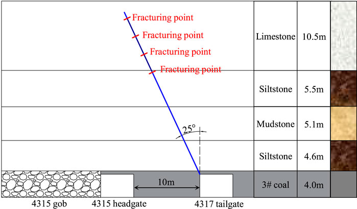
Figure 16. Roof cutting scheme.
In addition to the original support scheme, supplementary φ22 × 5,300 mm roof anchor cables were installed, with two anchors every two rows. Rib anchor cables, also φ22 × 5,300 mm, were installed every two rows in the coal pillar. The optimized support scheme is shown in Figure 17.
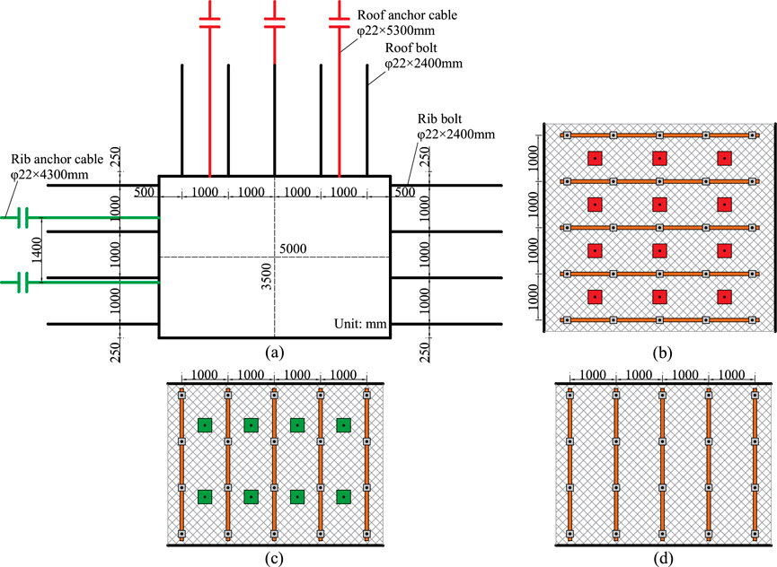
Figure 17. Optimized support scheme. (a) Support section. (b) Top view of roof. (c) Side view of coal pillar rib. (d) Side view of solid coal rib.
5.3 Application results
After the roadway excavation, a surface displacement monitoring station was set up 200 m away from the open-off cut to monitor the surrounding rock’s convergence and deformation in real time. Continuous monitoring over 80 days of the monitoring section resulted in the surrounding rock deformation curve shown in Figure 18.
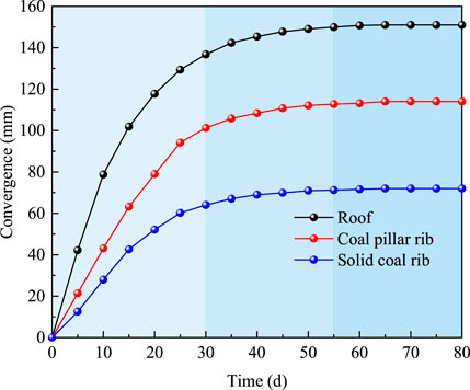
Figure 18. Roadway deformation during excavation.
After the excavation of the roadway, a surface displacement monitoring station is set up 200 m away from the open cut to monitor the convergence deformation of the surrounding rock in real time.
From 0 days to 30 days, the surrounding rock deformation rate was large. From 30 days to 55 days, the deformation rate decreased significantly. After 55 days, the deformation stabilized. The final maximum deformation of the roadway roof, coal pillar rib, and solid coal rib were 151 mm, 114 mm, and 72 mm, respectively.
6 Conclusion
Based on the production geological environment of the 4,317 tailgate at Chengzhuang Coal Mine, the modified FLAC3D model was used to analyze the stability characteristics of coal pillar with different widths. The main conclusions are as follows:
(1) The internal and external stress field evolution of the surrounding rock during the GED was analyzed, and it was determined that the internal stress field ranged from 13.6 m to 15.2 m. According to the limit equilibrium theory, a coal pillar width of 10 m, within the internal stress field, is conducive to the stability of the roadway.
(2) Numerical simulation results show that in the analysis of stress and plastic zone distribution for coal pillars of different widths, the 10 m coal pillar is in a yield state, with internal stress peaks maintaining around 26 MPa. There is no excessive concentration or drastic change, and the stress distribution is reasonable, making it the optimal coal pillar width.
(3) A combined control technique of “hydraulic fracturing roof cutting + roof anchor cable + rib anchor cable” was proposed and successfully applied in the 4,317 tailgate. On-site monitoring results indicate that the surrounding rock deformation stabilized after 55 days, with good maintenance effects in the roadway.
Data availability statement
The original contributions presented in the study are included in the article/supplementary material, further inquiries can be directed to the corresponding author.
Author contributions
GL: Software, Writing – original draft. LG: Conceptualization, Writing – original draft. QM: Writing – original draft, Software. HL: Writing – review and editing.
Funding
The author(s) declare that financial support was received for the research and/or publication of this article. This research was funded by National Natural Science Foundation of China (52404151), Langfang science and technology support plan project (No. 2024013024).
Conflict of interest
The authors declare that the research was conducted in the absence of any commercial or financial relationships that could be construed as a potential conflict of interest.
The reviewer WY declared a shared affiliation with the author HL to the handling editor at time of review.
Generative AI statement
The authors declare that no Generative AI was used in the creation of this manuscript.
Publisher’s note
All claims expressed in this article are solely those of the authors and do not necessarily represent those of their affiliated organizations, or those of the publisher, the editors and the reviewers. Any product that may be evaluated in this article, or claim that may be made by its manufacturer, is not guaranteed or endorsed by the publisher.
References
Bertuzzi, R., Douglas, K., and Mostyn, G. (2016). An Approach to model the strength of coal pillars. Int. J. Rock Mech. Min. Sci. 89, 165–175. doi:10.1016/j.ijrmms.2016.09.003
Chang, Q., Ge, S., Shi, X., Sun, Y., Wang, H., Li, M., et al. (2022). Determination of narrow coal pillar width and roadway surrounding rock support technology in gob driving roadway. Sustainability 14 (8), 4848. doi:10.3390/su14084848
Chen, A. (2021). Width design of small coal pillar of gob-side entry driving in soft rock working face and its application of zaoquan coal mine. Adv. Civ. Eng. 2021 (1), 9999957. doi:10.1155/2021/9999957
Chen, D., Wang, X., Bai, J., and Li, M. (2024c). Characteristics of waterproof failure and optimal width of narrow coal pillars under the coupled effects of mining, excavation and seepage. Geomechanics Geophys. Geo-Energy Geo-Resources 10 (1), 100. doi:10.1007/s40948-024-00825-2
Chen, D., Wang, X., Bai, J., Lu, J., Wu, B., Li, X., et al. (2025). Advanced detection methods for tunnels and roadways: a review. Meas. Sci. Technol. 36 (1), 012007. doi:10.1088/1361-6501/ad98b2
Chen, D., Wang, X., Bai, J., Xu, C., Chu, Y., Hou, B., et al. (2024a). Research on the stability mechanism and control technology of surrounding rock in filling working face with gob-side entry retaining. Sustainability 16 (24), 11058. doi:10.3390/su162411058
Chen, D., Wang, X., Bai, J., and Zhang, F. (2024d). Deformation mechanism and control technology of gob-side roadway with continuous mining and continuous backfilling: a case study. Geomatics, Nat. Hazards Risk 15 (1), 2350480. doi:10.1080/19475705.2024.2350480
Chen, D., Wang, X., Wu, S., Zhang, F., Fan, Z., Wang, X., et al. (2023). Study on stability mechanism and control techniques of surrounding rock in gob-side entry retaining with flexible formwork concrete wall. J. Central South Univ. 30 (9), 2966–2982. doi:10.1007/s11771-023-5436-z
Chen, D., Wang, X., Zhang, F., Bai, J., Zhao, X., Li, M., et al. (2024b). Study on the mechanism of progressive instability of special-shaped coal pillar and the stability control of roadway under the influence of mining. Rock Mech. Rock Eng. 57 (8), 6461–6483. doi:10.1007/s00603-024-03798-6
Das, A. J., Mandal, P. K., Paul, P. S., and Sinha, R. K. (2019). Generalised analytical models for the strength of the inclined as well as the flat coal pillars using rock mass failure criterion. Rock Mech. Rock Eng. 52 (10), 3921–3946. doi:10.1007/s00603-019-01788-7
Guo, S., Hu, S., Huang, J., Gao, Z., Cheng, Y., Han, J., et al. (2023). Stability control technology for surrounding rocks in gob-side entry driving with small coal pillars under dynamic pressure. Energies 16 (23), 7887. doi:10.3390/en16237887
Han, C., Yuan, Y., Zhang, N., Zhao, Y., Zhang, Q., Song, K., et al. (2022). Thick-anchored dual-layer locking supporting technique in gob-side entry driving with the narrow pillar: a case study. Geofluids 2022 (1), 5815411–5815414. doi:10.1155/2022/5815411
Han, P., Wang, K., Pang, J., Ji, X., and Zhang, C. (2025). Response properties of geometries of coal penetrating fracture on seepage behavior. Int. J. Min. Sci. Technol. 35 (2), 191–211. doi:10.1016/j.ijmst.2025.01.003
He, F., Zhai, W., Song, J., Xu, X., Wang, D., and Wu, Y. (2023). Reasonable coal pillar width and surrounding rock control of gob-side entry driving in inclined short-distance coal seams. Appl. Sci. 13 (11), 6578. doi:10.3390/app13116578
Jaiswal, A., and Shrivastva, B. K. (2009). Numerical simulation of coal pillar strength. Int. J. Rock Mech. Min. Sci. 46 (4), 779–788. doi:10.1016/j.ijrmms.2008.11.003
Jia, Y., Wang, Y., Zhuo, R., Lou, F., Jin, S., and Zhao, P. (2022). Research on the safety control technology of gob-side entry in inclined thick coal seam. Process Saf. Environ. Prot. 166, 241–248. doi:10.1016/j.psep.2022.08.019
Jiang, L., Yang, Z., and Li, G. (2021). Research on the reasonable coal pillar width and surrounding rock supporting optimization of gob-side entry under inclined seam condition. Adv. Civ. Eng. 2021 (1), 7145821. doi:10.1155/2021/7145821
Li, H., Gao, S., Chen, D., Xie, S., Wu, Y., Feng, S., et al. (2023). Study on the stability of coal pillars in a gob-side two-entry arrangement of different layers in fully mechanized caving and the zonal linkage control of “heteromorphic” surrounding rock. Processes 11 (6), 1806. doi:10.3390/pr11061806
Li, J., Wang, W., Li, B., Tan, J., and Peng, B. (2021). Directionality of butterfly leaves and nonuniform deformation mechanism in gob-side entry driving roadway. J. Mech. 37, 291–301. doi:10.1093/jom/ufab004
Li, L., Bai, J., and Wang, X. (2012). Rational position and control technique of roadway driving along next goaf in fully mechanized top coal caving face. J. China Coal Soc. 37 (9), 1564–1569.
Liu, F., and Han, Y. (2021). Deformation mechanism and control of the surrounding rock during gob-side entry driving along deeply fully mechanized caving island working face. Geofluids 2021 (1), 1–12. doi:10.1155/2021/5515052
Liu, P., Gao, L., Zhang, P., Wu, G., Wang, C., Ma, Z., et al. (2022). A case study on surrounding rock deformation control technology of gob-side coal-rock roadway in inclined coal seam of a mine in guizhou, China. Processes 10 (5), 863. doi:10.3390/pr10050863
Liu, X., Tu, S., Hao, D., Lu, Y., Miao, K., and Li, W. (2021). Deformation law and control measures of gob-side entry filled with gangue in deep gobs: a case study. Adv. Mater. Sci. Eng. 2021 (1), 9967870. doi:10.1155/2021/9967870
Liu, X., Xu, H., Li, B., He, W., Liang, X., and Xia, H. (2023). Study on surrounding rock failure law of gob-side entry based on the second invariant of deviatoric stress. Sustainability 15 (13), 10569. doi:10.3390/su151310569
Lu, J., Yin, T., Guo, W., Men, J., Ma, J., Yang, Z., et al. (2024). Dynamic response and constitutive model of damaged sandstone after triaxial impact. Eng. Fail. Anal. 163, 108450. doi:10.1016/j.engfailanal.2024.108450
Ma, Z., Chen, C., Liang, X., Chen, A., and Song, W. (2020). Field and numerical investigation on the stability of coal pillars of gob-side entry driving with top coal. Arabian J. Geosciences 13 (22), 1193. doi:10.1007/s12517-020-06234-5
Qi, F., Zhou, Y., Cao, Z., Zhang, Q., and Li, N. (2016). Width optimization of narrow coal pillar of roadway driving along goaf in fully mechanized top coal caving face. J. Min. & Saf. Eng. 33 (3), 475–480.
Ren, Z., Zhang, C., Wang, Y., Yang, S., and Li, Q. (2025). Collaborative movement characteristics of overlying rock and loose layer based on block–particle discrete-element simulation method. Int. J. Coal Sci. & Technol. 12 (1), 17. doi:10.1007/s40789-025-00762-9
Shan, R., Liu, S., Wang, H., Li, Z., Huang, P., and Dou, H. (2024). Research on the deformation mechanism and ACC control technology of gob-side roadway in an extra-thick coal seam with varying thickness. Energy Sci. & Eng. 12 (5), 1913–1933. doi:10.1002/ese3.1720
Shi, X., Jing, H., Zhao, Z., Gao, Y., Zhang, Y., and Bu, R. (2020). Physical experiment and numerical modeling on the failure mechanism of gob-side entry driven in thick coal seam. Energies 13 (20), 5425. doi:10.3390/en13205425
Sun, L., Ding, B., Li, W., Chen, Z., Shang, D., Zhang, Y., et al. (2023). Width optimization and application of narrow coal pillar in gob-side entry driven in thick coal seam in Luzigou Mine. J. Min. & Saf. Eng. 40 (6), 1151–1160.
Tan, Y., Xu, H., Yan, W., Guo, W., Sun, Q., Yin, D., et al. (2022). Development law of water-conducting fracture zone in the fully mechanized caving face of gob-side entry driving: a case study. Minerals 12 (5), 557. doi:10.3390/min12050557
Wang, E., and Xie, S. (2022). Determination of coal pillar width for gob-side entry driving in isolated coal face and its control in deep soft-broken coal seam: a case study. Energy Sci. & Eng. 10 (7), 2305–2316. doi:10.1002/ese3.1139
Wang, H., Shuang, H., Li, L., and Xiao, S. (2021). The stability factors’ sensitivity analysis of key rock B and its engineering application of gob-side entry driving in fully-mechanized caving faces. Adv. Civ. Eng. 2021 (1), 9963450. doi:10.1155/2021/9963450
Wang, K., Huang, Y., Gao, H., Zhai, W., Qiao, Y., Li, J., et al. (2020). Recovery technology of bottom coal in the gob-side entry of thick coal seam based on floor heave induced by narrow coal pillar. Energies 13 (13), 3368. doi:10.3390/en13133368
Wang, M., Wang, W., Xu, Y., Xie, G., Qin, J., Liu, H., et al. (2024a). Study on the new layout pattern about the gob-side entry under dynamic pressure and its surrounding rock stability control. Energy Sci. & Eng. 12 (4), 1389–1410. doi:10.1002/ese3.1667
Wang, M., Zheng, H., Ma, Z., Mu, H., and Feng, X. (2023). Control technology of roof-cutting and pressure relief for roadway excavation with strong mining small coal pillar. Sustainability 15 (3), 2046. doi:10.3390/su15032046
Wang, Y., Zhao, Z., Zhang, W., Wei, X., and Hui, Z. (2024b). Deformation mechanism and control technology of gob-side entry retaining with roadside backfilling: a numerical analysis and field investigation. Geomechanics Geophys. Geo-Energy Geo-Resources 10 (1), 175. doi:10.1007/s40948-024-00901-7
Xie, S., Guo, F., and Wu, Y. (2022). Control techniques for gob-side entry driving in an extra-thick coal seam with the influence of upper residual coal pillar: a case study. Energies 15 (10), 3620. doi:10.3390/en15103620
Xie, S., Li, H., Chen, D., Feng, S., Yang, J., Ma, X., et al. (2024). Research on the control technology and key parameters of external anchor-internal unloading of surrounding rock during gob-side entry driving under severe mining of 1000-m-Deep mine. Rock Mech. Rock Eng. 57 (4), 2913–2932. doi:10.1007/s00603-023-03722-4
Xu, L., Ma, Y., Elmo, D., Ding, S., Zhu, H., Liu, H., et al. (2024). Parameters and surrounding rock control of gob-side driving under double key stratum after roof cutting. Sci. Rep. 14 (1), 5106. doi:10.1038/s41598-024-55679-1
Xue, Y. (2024). Optimization of small coal pillar width and control measures in gob-side entry excavation of thick coal seams. Sci. Rep. 14 (1), 23304. doi:10.1038/s41598-024-74793-8
Yang, X., Yu, F., Ma, C., Zhang, T., Wang, B., and Zhao, X. (2023). Study on floor heave characteristics and the control method of gob-side entry driving in weakly cemented soft rock. Sustainability 15 (5), 3969. doi:10.3390/su15053969
Yin, T., Lu, J., Guo, W., Wu, Y., and Ma, J. (2024a). Dynamic mechanical response and damage constitutive model of end-jointed rock bridge with different water content states under impact load. Theor. Appl. Fract. Mech. 130, 104255. doi:10.1016/j.tafmec.2024.104255
Yin, T., Men, J., Lu, J., Wu, Y., Guo, W., Yang, Z., et al. (2024b). Study on dynamic mechanical properties and microscopic damage mechanisms of granite after dynamic triaxial compression and thermal treatment. Case Stud. Therm. Eng. 61, 104910. doi:10.1016/j.csite.2024.104910
Zhang, B., Wang, P., Cui, S., Fam, M., and Qiu, Y. (2021). Mechanism and surrounding rock control of roadway driving along gob in shallow-buried, large mining height and small coal pillars by roof cutting. J. China Coal Soc. 46 (7), 2254–2267.
Zhang, G., Chen, L., Wen, Z., Chen, M., Tao, G., Li, Y., et al. (2020). Squeezing failure behavior of roof-coal masses in a gob-side entry driven under unstable overlying strata. Energy Sci. & Eng. 8 (7), 2443–2456. doi:10.1002/ese3.678
Zhang, J., Gao, S., Liu, H., Yang, T., Wu, J., He, Y., et al. (2024). Study on roadway roof deformation and coal pillar energy accumulation instability. Sci. Rep. 14 (1), 27603. doi:10.1038/s41598-024-78808-2
Keywords: gob-side entry driving, coal pillar, internal and external stress field, hard roof, numerical simulation
Citation: Li G, Gao L, Ma Q and Liu H (2025) Research on the optimization and application of coal pillar width in gob-side entry driving under hard roof condition. Front. Earth Sci. 13:1603252. doi: 10.3389/feart.2025.1603252
Received: 31 March 2025; Accepted: 30 April 2025;
Published: 26 May 2025.
Edited by:
Chong Xu, Ministry of Emergency Management, ChinaReviewed by:
Cun Zhang, China University of Mining and Technology, Beijing, ChinaWei Yu, China University of Mining and Technology, China
Qingwen Zhu, Shandong University of Science and Technology, China
Yinwei Wang, China University of Mining and Technology, Beijing, China
Shixing Cheng, Shanxi Institute of Science and Technology, China
Li Ji, Xi`an University of Science and Technology, China
Liang Li, China University of Mining and Technology, Beijing, China
Chao Wu, Tsinghua University, China
Copyright © 2025 Li, Gao, Ma and Liu. This is an open-access article distributed under the terms of the Creative Commons Attribution License (CC BY). The use, distribution or reproduction in other forums is permitted, provided the original author(s) and the copyright owner(s) are credited and that the original publication in this journal is cited, in accordance with accepted academic practice. No use, distribution or reproduction is permitted which does not comply with these terms.
*Correspondence: Qi Ma, Y3VtdGNrZ2NAMTYzLmNvbQ==