 Yuan Yang1
 Liu Liu
- 1The 4th Engineering Company of China Railway 12th Bureau Group Ltd., Co., Xi’an, China
- 2Department of Road and Bridge Engineering, Hebei Jiaotong Vocational and Technical College, Shijiazhuang, China
- 3School of Civil Engineering, Shijiazhuang Tiedao University, Shijiazhuang, China
In view of the problem of the plastic state of the surrounding rock of loess high-speed railway tunnels changing from hard plastic to soft-plastic, even in a flow-plastic state with increasing moisture content, and appearing collapse and large deformation of support structure, it is put forward to use advanced pipe-roof support. Numerical simulation and site monitoring and measurement are adopted to analyze the tunnel surrounding rock deformation characteristics when different soft-plastic layer thicknesses (1 m, 3 m, 5 m) distributing on tunnel arc, sidewall and invert, and the control effect of advanced pipe-roof support to tunnel construction deformation. Results show: ① The spatial distribution of soft-plastic loess layer has a much greater impact on deformation than its thickness. Vertical and horizontal displacements of the tunnel surrounding rock appear three stages: rapid deformation during the initial stage of excavation, continuous slow deformation and tending towards stable convergence deformation. ② Compared to the situation of no pipe–roof, implement of advance pipe-roof support can significantly improve the control effect of vertical and horizontal displacements of the tunnel surrounding rock. ③ The tunnel surrounding rock deformation characteristics show: it is crucial to control the deformation of surrounding rock from the initial excavation stage to the primary support and sealing before forming a ring. The use of advanced pipe-roof support has a significant effect on controlling deformation during the construction of soft-plastic loess high-speed railway tunnels.
1 Introduction
The topography in China features nearly 635,000 square meters of loess strata, which accounts for 6.6% of the nation’s total land area. Among these regions, the “Loess Plateau” in the western parts of Shaanxi and Gansu provinces is particularly notable (Cao et al., 2018). This plateau encompasses a continuous area of approximately 440,000 square kilometers, with loess layer thicknesses ranging from 100 to 200 m, and in some regions, reaching up to 400 m (Nakajima et al., 2021; Qin et al., 2024). It is renowned globally for its well-preserved stratigraphic sequences and distinctive landforms. Consequently, the loess layer presents a significant engineering geological background for railway, tunnel, and underground construction projects in the western region.
Loess is a unique soil type characterized by its distinct properties as a Quaternary sediment, which diverges significantly from contemporaneous sediment types. Its mechanical properties are notably variable, influenced by factors such as formation age and moisture content (Zhang, 2020). Compared to conventional rock masses, construction in loess is associated with greater disturbance and damage to the original stable strata. Meanwhile, increased excavation span, enhanced disturbance of surrounding rock, the effects of joints and fissures, and the soil’s sensitivity to moisture lead to significant alterations in the engineering properties of the loess. The soil transitions from a hard-plastic state to a soft -plastic state and may even reach a flow-plastic state.
When the loess layer is in a soft-plastic state, its porosity and moisture content increase, (where natural moisture content is generally greater than 25%), while its strength diminishes. These properties make it more susceptible to disturbances during construction. As a result, tunnels constructed through soft plastic loess layers are more prone to excessive deformation, such as over-limit conditions, cracking of the primary suppport, twisting of the steel arch frame, instability at the arch feet, and bulging of the inverted arch. In severe cases, local section collapses can occur (Li et al., 2018). If not addressed promptly, these issues can lead to safety accidents or even catastrophic failures, which significantly impacts construction safety and quality, as well as the subsequent operational processes. Notable instances, such as Hanjialing Tunnel, Yangzong Tunnel, Letuan Tunnel, and Gongbei Tunnel, illustrate the criticality of addressing these concerns to meet traffic demands (Chen et al., 2005; Anna et al., 2011; Li J. et al., 2021; Zhou et al., 2021; Cai et al., 2022). Given the unique challenges posed by large-section, shallow loess tunnels, analyzing the stability of surrounding rock following tunnel excavation is essential for ensuring construction safety.
Currently, extensive research has been conducted worldwide on the construction of loess tunnels. For instance, Tu et al. (2020) examined the Xinggongjie station tunnel of Dalian Metro Line one and studied the deformation of surrounding rock and mechanical characteristics of supporting structure under different excavation methods using numerical simulation method. Wu et al. (2018) analyzed the construction interaction mechanisms and stratum deformation patterns of subway tunnels in Shenzhen Metro Line seven using numerical simulation method. Hu et al., 2012 investigated the deep deformation characteristics of surrounding rock in a large-section loess tunnel on the Lanzhou-Chongqing Railway through three-dimensional numerical simulations and field tests. Qiu et al. (2021) focused on a shallow loess tunnel to derive the time distribution curves of surface subsidence and tunnel convergence at the tunnel entrance through field tests and established a tunnel deformation prediction model based on field monitoring data. Wang (2011) analyzed the surrounding rock deformation law of an ultra-shallow loess tunnel under large eccentric pressure using numerical simulations and field tests. They discussed the causes of large deformation and proposed treatment measures. Wang (2012) studied the deformation characteristics and construction deformation control technology of a collapsible loess tunnel with high water content on the Baolan Passenger Dedicated Line. Li et al., 2021 analyzed the stratum response characteristics and its influencing factors during the excavation of a shallow, large-span loess tunnel. Cheng and Wang (2013) evaluated six construction methods for simulating loess tunnels and analyzed the displacements at control points within the surrounding rock. Liang et al., 2013 investigated the instability mechanism in a deep, large-section loess tunnel using model tests. Wang and Tannant (2004) performed numerical simulations on lined and unlined tunnels to analyze the influence of tunnel lining on surrounding rock. Tan et al. (2009) assessed various arch types in large-section tunnels on Zhengzhou-Xi’an high-speed railway and found that the CD method, CRD method, or double-side heading method provided effective outcomes. Lin et al. (2022) adjusted the construction method of CRD based on the monitoring data, Ensured construction safety. Gong et al. (2019) utilized a multiple failure test approach to derive the mechanical properties of rock masses under different confining pressures. Li et al. (2011) analyzed primary supporting forces and surrounding rock deformations in the Zhengzhou-Xi 'an high-speed railway tunnels through on-site inspection. Chen et al. (2022), analyzed the effect of different fracture distribution modes (fracture angle, fracture position and fracture combination) on the shear strength of loess is investigated by carrying out consolidated undrained triaxial shear tests. Gong et al. (2020) employed the discrete element method to establish a simulation model that considers sedimentation angle, confining pressure, loading speed, and hydrate saturation, which was then employed to conduct bi-axial compression simulation of the model.
While significant advancements have been achieved in understanding deformation control during the construction of loess tunnels and analyzing surrounding rock deformation characteristics, targeted analysis concerning the construction challenges posed by tunnels traversing soft-plastic loess layers remains underdeveloped. Therefore, this study focuses on the Luochuan Tunnel currently under construction on the Xiyan high-speed Railway. It investigates the deformation of surrounding rock under varying thicknesses and positions of soft-plastic loess layers. Subsequently, relevant deformation control measures are proposed to ensure the construction safety of the soft-plastic loess section of the Luochuan Tunnel. The findings provide valuable insights for similar projects in the future.
2 Engineering background
2.1 Project overview
The newly constructed Xi’an-Yan’an high-speed railway line is located in Guanzhong and northern Shaanxi. This double-track high-speed railway is designed to operate at a design speed of 350 km/h. It has a total length of 287.059 km and a newly-built line length of 281.968 km. The railway features 43 new tunnels along the main line, which collectively extend 165.751 km, accounting for 58.8% of the newly constructed line. The route traverses several geographical areas, including Weihe River alluvial plain area, loess tableland area, loess ridge gully area, and Ziwuling low mountain area. The Quaternary strata along the line predominantly consist of Holocene alluvium, diluvium, landslide accumulation layer, and artificial accumulation layer, as well as upper and Middle Pleistocene alluvium and aeolian deposits. The primary lithology includes clay (sandy) loess, with local occurrences of filled soil, silty clay, sandy soil, and gravel soil. The underlying bedrock is mainly composed of Paleogene, Jurassic, Triassic, Permian, Carboniferous, and Ordovician periods. The lithology is mainly shale, sandstone, mudstone, limestone, and conglomerate. The rock stratum exhibits a slight inclination.
The Luochuan Tunnel is located in Houzitou Township, Luochuan County, Yan 'an City, Shaanxi Province. It extends from DK194 + 759.57 to DK198 + 900, with a total length of 4140.43 m. It is a double-track medium-long tunnel. The tunnel’s entrance is situated on the slope of Huangtuliang, with the trajectory from the entrance to the exit being uphill. The burial depth of the tunnel decreases from the starting point to the endpoint. It ranges from a maximum depth of 64 m to a minimum depth of 8 m, indicating that the entire tunnel is relatively shallow. The tunnel excavation section measures 15.6 m in width, 13.18 m in height, and a cross-sectional area of 167.3 m2, as illustrated in Figure 1.
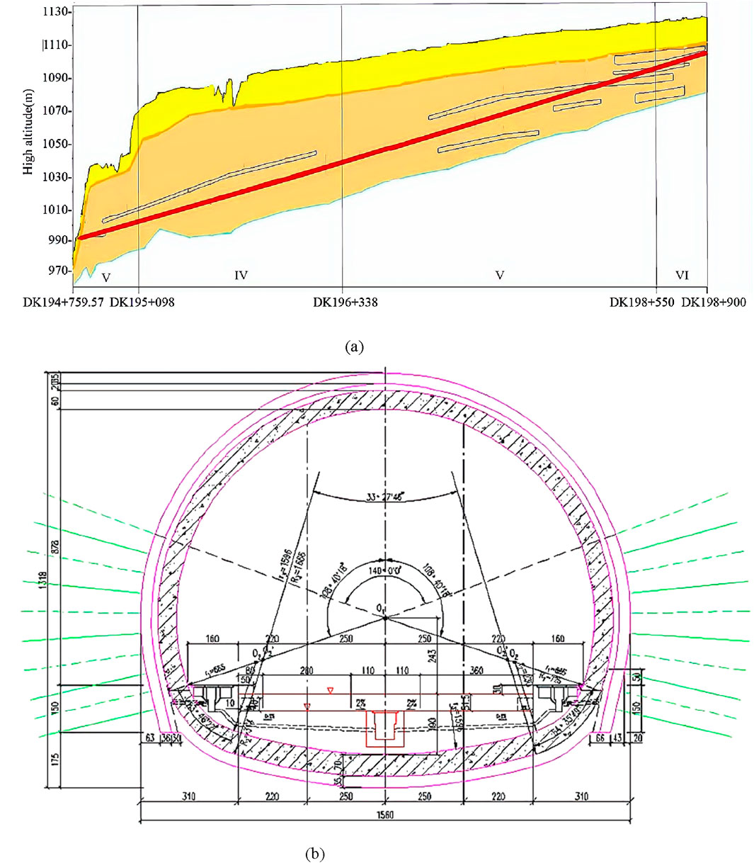
Figure 1. Newly-built Xi 'an-Yan 'an high-speed Railway. (a) Profile of Luochuan Tunnel. (b) Tunnel lining section.
2.2 Engineering geology and hydrology
The surrounding rocks of the tunnel are classified into Grade IV, Grade V, and Grade VI. Their respective lengths are 1240 m, 2531 m, and 331 m. Notably, 3,412 m of the tunnel consist of loess geological material in a soft plastic state. This soft plastic loess distributed throughout the tunnel, with concentrations primarily located at the top, body, and bottom. Specifically, in the section between DK194 + 800 and DK195 + 700, the soft-plastic loess is mainly found in the body and upper part of the tunnel, while in the section between DK197 + 560 and DK198 + 470, it is found in the body and lower part of the tunnel. The water content of the loess ranges from a minimum of 14.4% to a maximum of 27.4%. During construction, it is crucial to reinforce vault support and treatment of the tunnel base, monitor the water content of the loess, implement waterproofing and drainage measures, and ensure timely closure of the supports. These precautions are essential to prevent hazards such as soil deformation and collapse, which may result from prolonged exposure of the tunnel face to seepage and soaking.
The strata at the tunnel site are mainly Quaternary Holocene upper and middle Pleistocene aeolian deposits. The Quaternary Upper Pleistocene features clayey loess on the surface of loess beam, with thicknesses ranging from 5 to 20 m. Paleosols are often found at the bottom of loess beams, and their thicknesses range from 2 to 4 m. The Quaternary Middle Pleistocene consists of clayey loess within the loess beams, with thicknesses of 10–30 m; numerous paleosols are also present within this layer, generally measuring 3–8 m in thickness.
The geological structure in this area is relatively undeveloped. At the entrance site, the soil condition is classified as self-weight collapsible loess with a medium collapsible grade (Grade II) and a thickness of 15–25 m. Conversely, the exit site is categorized as self-weight collapsible loess with a serious collapsible grade (Grade IV) and a thickness of 25–30 m. Paleosol is the weakly expansive soil.
The tunnel traverses the loess plateau, with the Xiangu River at the entrance and Heimugou and Qujia River flowing on either side. The exit is located on the plateau, and the adjacent gullies exhibit year-round flow, which varies seasonally. During the dry season, the flow rate in the gully is approximately 5626 m3/d, located about 1650 m to the right of tunnel DK195 + 682, and 4166 m3/d, situated roughly 380 m to the left of tunnel DK195 + 075. Groundwater in the tunnel area is primarily pore phreatic water in the Quaternary unconsolidated layer. The groundwater level is significantly controlled by the rainfall, the size of loess plateau, and the thickness of loess layer. The tunnel is located above the groundwater level, and the available water supply is generally poor, leading to potential seepage and dripping during construction in the rainy season.
3 Analysis of deformation characteristics of surrounding rock in tunnels passing through soft-plastic loess layers
3.1 Numerical model and parameter selection
In this study, numerical analyses are performed using MIDAS-GTS finite element software. The selection of material parameters is based on the equivalent stiffness method, which considers the material properties of surrounding rock in each layer as well as the physical and mechanical parameters of the supporting structures utilized in the modeling process. Typically, the elastic modulus and bulk density of the steel arch frame are converted into those of concrete while ensuring the equivalence of compressive stiffness. The relationship expression is shown in Equation 1:
where
Based on a review of geological exploration reports and relevant literature, and by disregarding soil layers with minimal thickness, the strata are ultimately divided into four layers: Q3 loess, Q2 loess (I), Q2 loess (II), and Q2 soft-plastic loess. The parameters for the soil strata and supporting structures selected for the modeling process are presented in Tables 1 and 2.
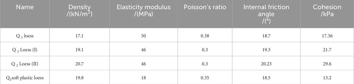
Table 1. Physical and mechanical parameters for soil strata.
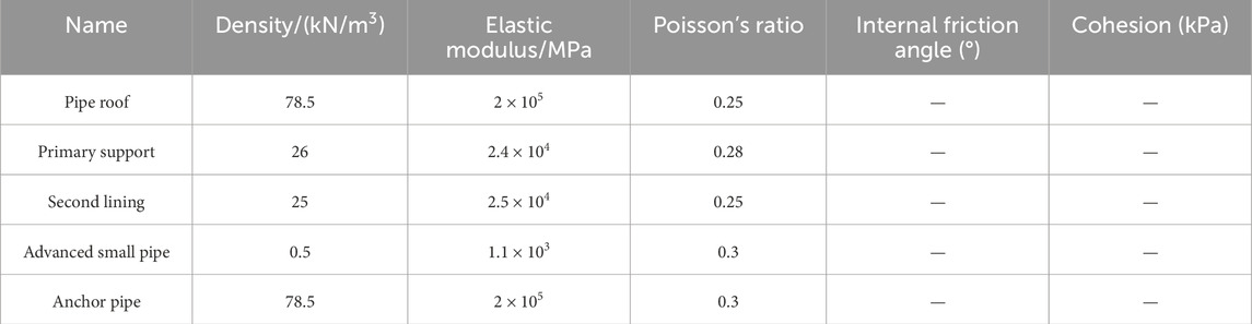
Table 2. Parameters for supporting structures.
According to the Saint-Venant principle, the excavation disturbance range of the tunnel is estimated to be 3 to 5 times the tunnel’s diameter. To eliminate the influence of the boundary effect on the numerical results and to accommodate the requirements of the working conditions, the overall dimensions of the model are established at 100 m × 80 m×60 m (X × Y × Z), as illustrated in Figure 2.
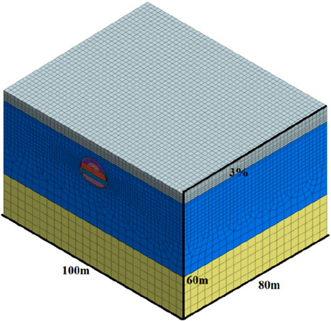
Figure 2. Numerical model.
The actual thickness of the soft-plastic loess layer in the Luochuan Tunnel ranges from 0.8m to 6.4 m. A uniform layer thickness of 5 m is selected to establish calculation models of soft-plastic loess layers distributed at different locations, as shown in Figure 3. Numerical models of soft-plastic loess layers with different thicknesses,as shown in Figure 4.
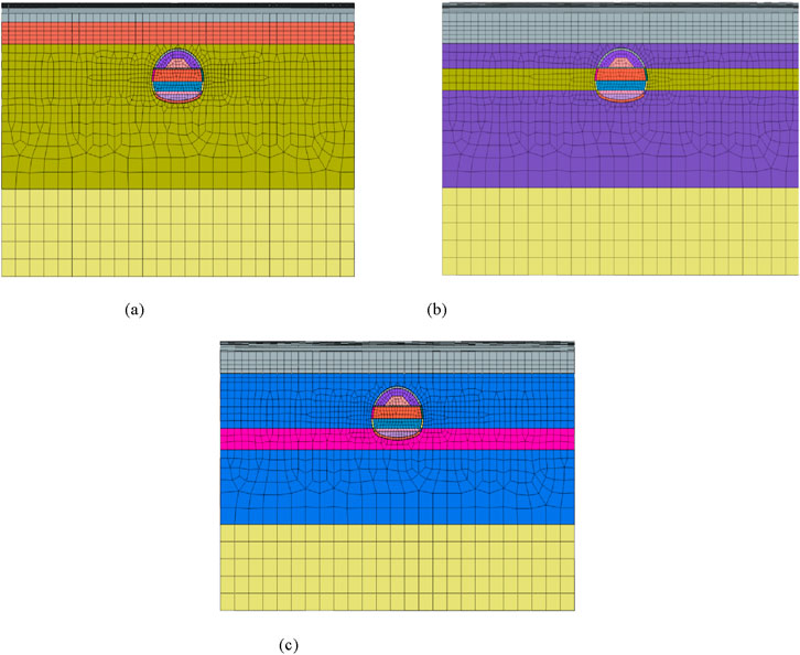
Figure 3. Numerical models of soft-plastic loess layers distributed at different locations. (a) Soft-plastic loess at the vault (b) Soft-plastic loess at the side wall. (c) Soft-plastic loess at the inverted arch.
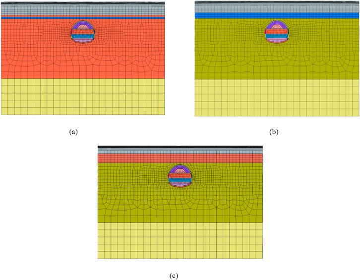
Figure 4. Numerical models of soft-plastic loess layers with different thicknesses. (a) 1 m. (b) 3 m. (c) 5 m.
The side and bottom boundaries are fixed, while the top surface is designated as a free boundary. The Mohr-Coulomb constitutive model is chosen for calculation. The tectonic stress is excluded from the modeling, while the effect of self-weight stress is incorporated as the initial geostress.
The model tunnel excavation adopts a three-bench reserved core soil method. During the simulation process, the construction stages are organized according to the actual site conditions. The tunnel excavation and the construction of the supporting structures are simulated using the 'activation’ and 'passivation’ commands in the software. Additionally, advanced support is simulated by adjusting the soil parameters in the reinforcement area.
3.2 Analysis of deformation characteristics of surrounding rock under different working conditions
3.2.1 Deformation characteristics of surrounding rock when the soft-plastic loess layer is distributed at different locations
The time-dependent vertical displacement curves of the soft-plastic loess layers are illustrated in Figure 5, while the horizontal deformation curves of the surrounding rock are shown in Figure 6.
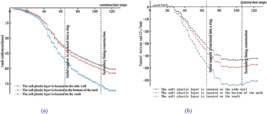
Figure 5. Vertical displacement curves of the surrounding rock. (a) Vault settlement (b) Bottom uplift.
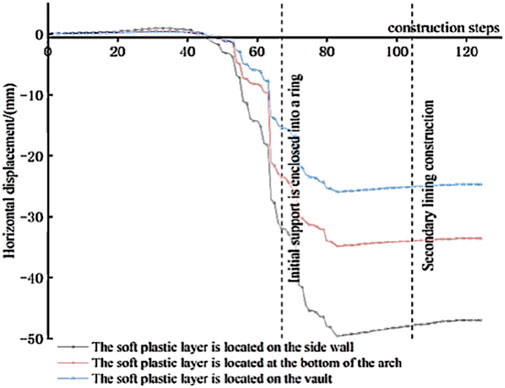
Figure 6. Horizontal displacement curves of the surrounding rock.
Figure 5 demonstrates that, for the same layer thickness, the spatial distribution of the soft-plastic loess layer significantly influences the vertical deformation of the surrounding rocks. When the soft-plastic loess layer is located at the vault, the maximum settlement reaches 81.84 mm, while the maximum uplift is 66.81 mm. When the soft-plastic loess layer is located at the side wall, the maximum settlement is 60.81 mm, while the maximum uplift is 42.15 mm. When the soft-plastic loess layer is located at the inverted arch, the maximum settlement is 64.67 mm, while the maximum uplift is 47.34 mm. Comparing these deformation amounts indicates that the vertical displacement values are consistently greater when the soft-plastic layer is located at the vault. This indicates that this configuration exerts the greatest impact on the construction. Additionally, the vertical deformation curves illustrate that the deformation of the surrounding rock goes progresses through three stages: rapid deformation at the beginning of excavation, slow deformation after the primary support closure, and stable deformation after secondary lining construction.
Figure 6 further reveals that the positional distribution of soft-plastic loess layers significantly affects the horizontal displacement of surrounding rock. Specifically, when the thickness of soft-plastic loess layers is 5 m and it is located at the vault, the maximum horizontal displacement is 24.67 mm. When the 5 m thick soft-plastic loess layer is located at the side wall, the maximum horizontal displacement is 47.02 mm. When the soft plastic loess layer is 5 m thick and is located at the inverted arch, the maximum horizontal displacement is 33.57 mm. These observations indicate that the side wall placement of the soft plastic loess layers exerts the greatest influence on the horizontal displacement of surrounding rock, while its positioning at the inverted arch also significantly affects the horizontal displacement. The influence is least pronounced when the layer is located at the vault. Similar to the vertical displacement curve, the horizontal deformation of the surrounding rock also undergoes three stages: rapid deformation at the beginning of excavation, slow deformation after the primary support closure, and stable deformation after the secondary lining construction. This finding suggests that managing deformation of the surrounding rock is crucial before the primary support achieves a complete ring.
3.2.2 Analysis of deformation characteristics of surrounding rock under different thicknesses of soft-plastic loess layers
It is observed that when the soft-plastic loess layer is located at the vault, it exerts the greatest influence on the vertical settlement of the surrounding rock. Conversely, when the soft-plastic loess layer is located at the side wall, it yields the greatest influence on the horizontal convergence of the surrounding rock. This section focuses on the analysis of the soft-plastic loess layer positioned above the vault. The influence of the thickness of the soft-plastic loess on surrounding rock deformation is analyzed. Thicknesses of 1 m, 3 m and 5 m are considered as the primary research variables. The established models are shown in Figure 4.
The time-dependent vertical displacement curves of the soft-plastic loess layers with different thicknesses are shown in Figure 7, while the horizontal deformation curves of the surrounding rock are presented in Figure 8.
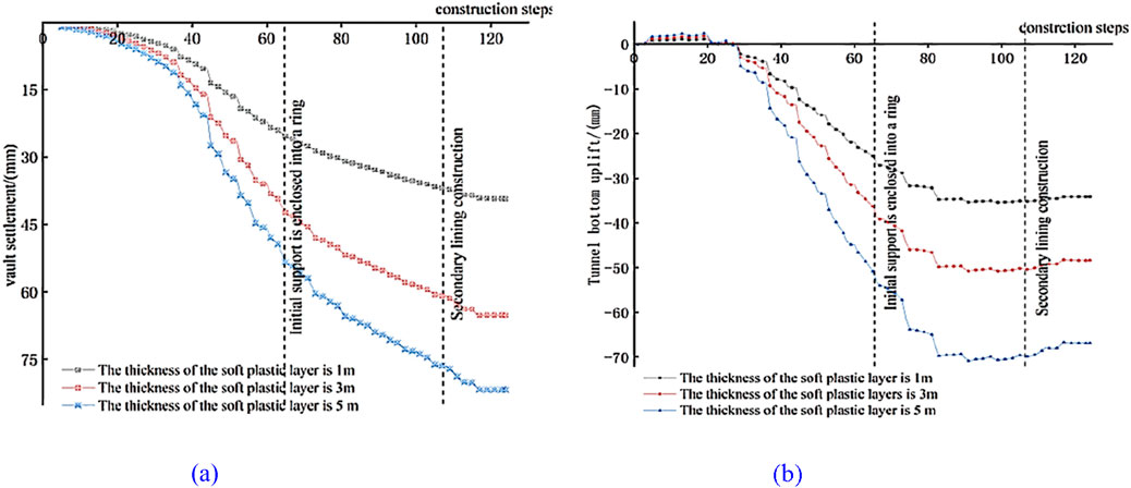
Figure 7. Vertical displacement curves of the surrounding rock. (a) Vault settlement (b) Bottom uplift.
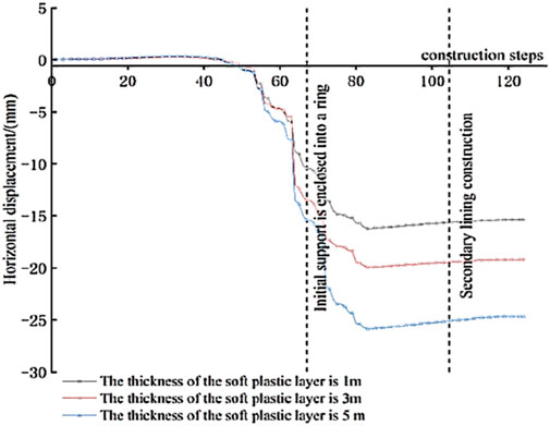
Figure 8. Horizontal displacement curves of the surrounding rock.
As illustrated in Figures 7, 8, the thickness of soft-plastic loess layer has a minimal influence on the horizontal displacement of surrounding rock. Specifically, when the thickness of soft-plastic loess layer above the vault is 1 m, the maximum horizontal displacement of the surrounding rock is 15.37 mm. When the thickness of soft-plastic loess layer above the vault is 3 m, the maximum horizontal displacement of the surrounding rock is 19.22 mm. When the thickness of soft-plastic loess layer above the vault is 5 m, the maximum horizontal displacement of the surrounding rock is 24.67 mm. This indicates that the appearance of soft-plastic loess layer increases the horizontal deformation of the surrounding rock to a certain extent, and variations in the thickness of soft-plastic loess layer also influence the horizontal displacement of the surrounding rock.
Furthermore, the deformation characteristics of the surrounding rock are remain consistent regardless of the spatial distribution of the soft plastic layer. Both vertical and horizontal displacements of the surrounding rocks undergo three stages: rapid deformation during the early stage of excavation, slow deformation after primary support closure, and stable deformation after secondary lining construction. These findings confirm that controlling the deformation of the surrounding rock is crucial before achieving a complete closure of the primary support.
3.3 Advanced support technology for the tunnel passing through soft-plastic loess layer
A comprehensive analysis of numerous construction cases involving loess tunnels reveals that the pipe roof advanced support method is effective in controlling tunnel face collapse and stratum deformation. The inherent stiffness of the pipe roof, coupled with its pronounced support capabilities, rapid construction process, and high safety profile, make it a preferred choice for preventing tunnel vault collapse and roof fall. However, with the increasing prevalence of shallow excavation projects in recent years, the efficacy of short-distance pipe-shed advanced support has proven insufficient for the current demands of deformation control construction. Consequently, the technology associated with pipe roof support has evolved towards the implementation of medium and long pipe roofs.
In the section of the Luochuan Tunnel from DK195 + 000 to DK195 + 100, a soft-plastic loess layer with a thickness of 3 m is situated above the vault. A three-bench reserved core soil method is employed for tunnel excavation. Given the specific construction environment, φ89 mm pipe roofs and advanced small conduits are used for support. The circumferential spacing of the pipe roofs is 60 cm, and the external insertion angle ranges from 6° to 8°. Each ring measures 6 m in length. The horizontal overlap between adjacent rings is maintained at a minimum of 3 m. Ф42 advanced small conduits with a length of 3.5 m are placed between the pipe roofs, with a circumferential spacing of 0.6 m, an external insertion angle of 10°–15°, and a longitudinal loop of 2.4 m. When the advanced small conduits are used in conjunction with the steel frame, the horizontal lap length between two adjacent rows of small catheters is required to be no less than 1 m. The overall model and details of pipe roof advanced support are presented in Figure 9, the displacement nephograms of the surrounding rock are presented in Figure 10.
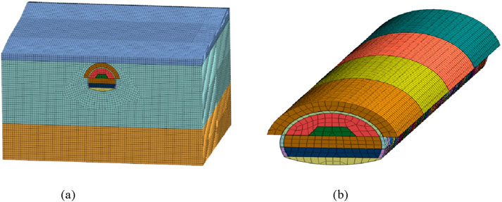
Figure 9. Model of advanced pipe roof. (a) Overall model (b) Model detail.
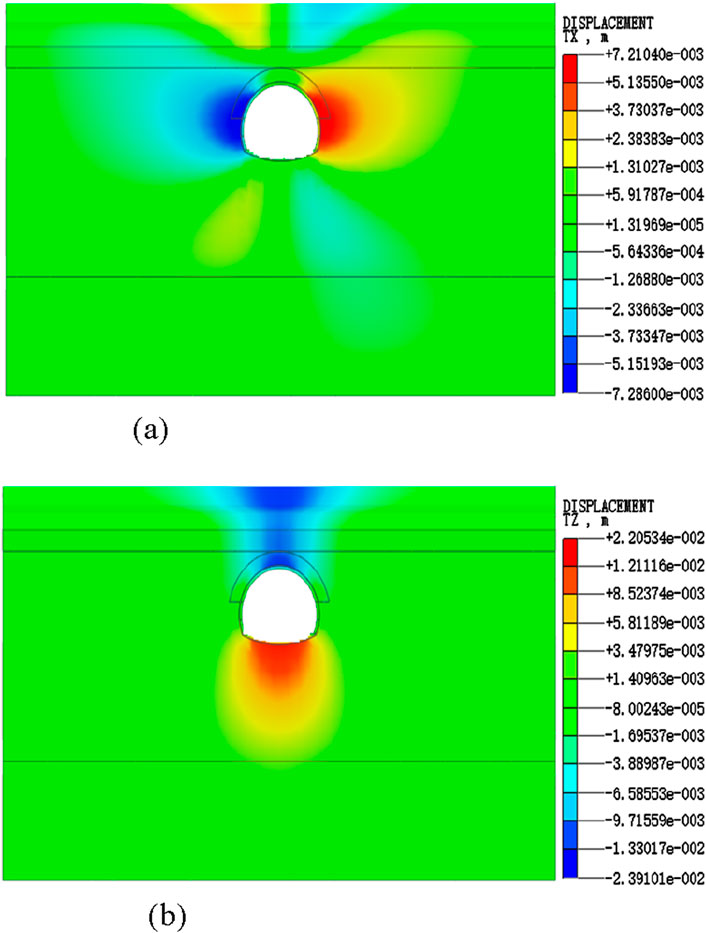
Figure 10. Displacement nephograms of the surrounding rock after the implementation of advanced pipe roofs. (a) Horizontal displacement nephogram. (b) Vertical displacement nephogram.
In contrast to the scenario of an invert covered with a 3-m thick soft-plastic loess layer without pipe roof reinforcement (illustrated in Figures 7, 8), the application of pipe roof significantly controls the deformation of surrounding rock. Figure 10 reveals that the vertical and horizontal displacements of the surrounding rock are improved under the action of advanced pipe roof compared to the situation without such support. Specifically, the maximum horizontal displacement of the surrounding rock is 7.29 mm on the left side and 7.21 mm on the right side. The maximum horizontal displacement is mainly concentrated in the left and right arches. The maximum vertical settlement of the surrounding rock is 23.91 mm, which reflcts a reduction rate of 63.46% compared to the scenario without pipe roof support. Additionally, the maximum uplift is 22.05 mm, which corresponds to a reduction rate of 54.41%. These findings indicate that the use of pipe roof support during the construction of the soft-plastic loess layer covering the tunnel vault is an effective method for controlling deformation.
3.4 Deformation analysis of surrounding rock based on on-site measurement
The loose surrounding rock and the poor self-stability of shallow soft-plastic loess sections make tunnel excavation susceptible to the collapse of surrounding rock, excessive deformation, and significant surface settlement. Therefore, it is crucial to implement monitoring sections to monitor the stress and deformation of surrounding rock and supporting structures during tunnel excavation. This monitoring allows for the assessment and verification of the stability of the tunnel section, thereby ensuring the safety of the construction process. To facilitate effective construction management based on real-time deformation monitoring of surrounding rock and supporting structures, the typical sections DK195 + 000 and DK195 + 050 of the Luochuan tunnel, along with their monitoring point layouts, are illustrated in Figure 11.
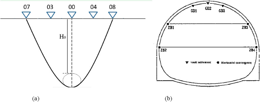
Figure 11. Layout of tunnel monitoring points. (a) Surface monitoring points (b) Monitoring points inside the tunnel.
3.4.1 Analysis of monitoring results of surface subsidence in typical sections
When the overlying soil layer above the tunnel is shallow, surface settlement exerts a more pronounced impact on the stress within the tunnel. Therefore, it is essential to conduct timely reliability evaluations based on the magnitude and rate of the surface settlement to guide the safe tunnel construction and ensure stable excavation. The surface monitoring data for the DK195 + 000 and DK195 + 050 sections are presented in Figures 12, 13.
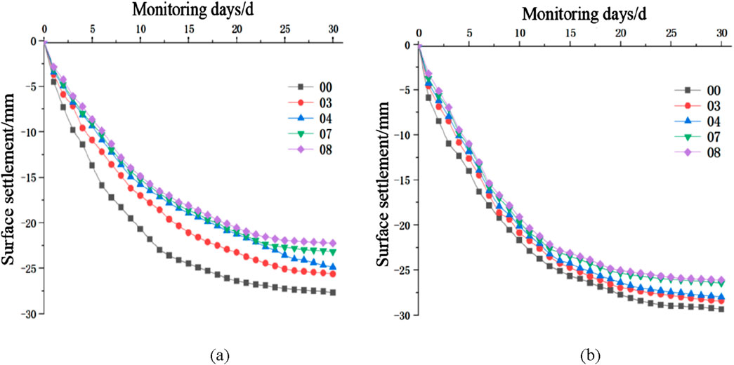
Figure 12. Surface settlement curves at different sections. (a) DK195 + 000 (b) DK195 + 050.
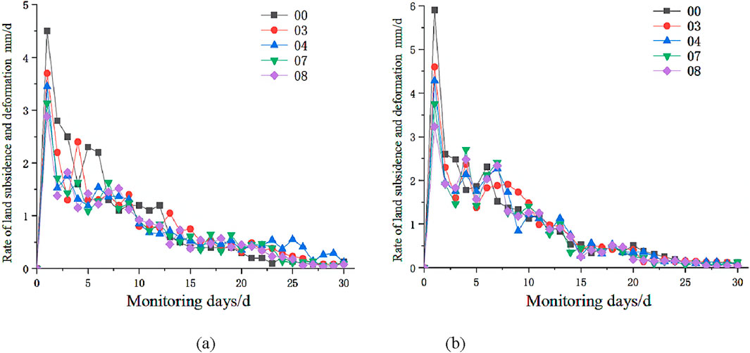
Figure 13. Surface settlement rate curves at different sections. (a) Dk195 + 000 (b) Dk195 + 050.
Figure 12 reveals that the maximum accumulated surface settlements for both monitored sections occurred at the centerline. In addition, as one moves laterally from the centerline, the accumulation of surface settlement decreases slightly, with the overall trend of cumulative surface settlement remaining consistent across all observation points. There are no obvious abrupt changes in the accumulated settlement at each observation point; rather, the deformation trend exhibits considerable activity in the early stage, slows during the middle stage, and stabilizes in the late stage.
Figure 13 depicts that there are fluctuations in the surface settlement rate at each observation point. Nonetheless, the overall trend indicates that during the early monitoring stage—coinciding within the initial tunnel excavation stage—the surface deformation rate exhibits considerable variability. In the middle stage, the deformation rate decreases with the change in the tunnel excavation deformation rate; however, there are still some fluctuations. The deformation rate becomes increasingly stable in the later monitoring stage. The maximum deformation rate of 6 mm/d occurs at the center line.
3.4.2 Analysis of vault settlement in typical sections
The settlement value of the tunnel vault serves as a direct indicator of the dynamic stress changes experienced by the surrounding rock and the supporting structure during tunnel construction. Monitoring the settlement of the vault allows for the evaluation and verification of the appropriateness of the tunnel excavation method and support systems. The vault settlement deformation curves for the sections DK195 + 000 and DK195 + 050 are illustrated in Figures 14, 15.
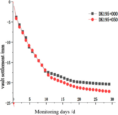
Figure 14. Vault settlement curves.
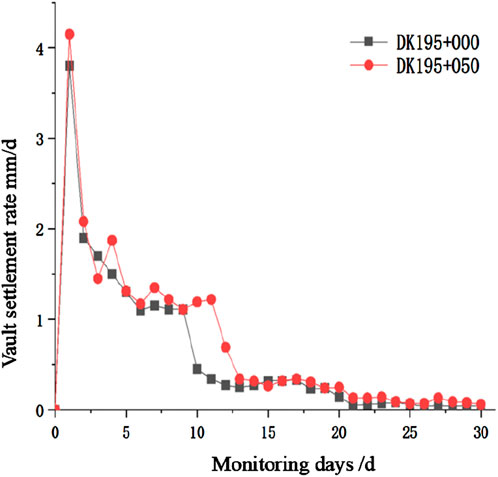
Figure 15. Vault settlement rate curves.
As shown in Figure 14, the vault settlement values for both monitoring sections exhibit a pattern characterized by significant deformation during the early stage, a reduction in deformation rate during the middle stage, and a stabilization of the deformation in the later stage. Figure 15 reveals that during the early stage of tunnel monitoring (0–5 days), the settlement rate of the vault in both sections is relatively high, displaying significant rate fluctuations. During the middle stage of monitoring (10–20 days), the settlement rate of the vault decreases significantly compared to the early stage, and the settlement rate remains basically at 0.5 mm/d. During the later stage of monitoring (20–30 days), the settlement rate approaches zero, indicating that the vault settlement stabilizes.
Therefore, the application of the supporting structure effectively controls the further release of surrounding rock stress, leading to a gradual stabilization of the surrounding rock. Additionally, during the late monitoring period, both the vault settlement and settlement rate tend to stabilize, contributing to the sustainability, safety, and efficacy of the tunnel construction process.
3.4.3 Analysis of horizontal displacement in typical sections
During the construction of shallow tunnels, it is essential not only to dynamically monitor surface settlement and vault settlement but also to assess the horizontal displacement surrounding the tunnel. Similar to vault settlement, horizontal displacement directly reflects the stress and deformation of tunnel surrounding rock. This measurement is crucial for evaluating the stability of surrounding rock during construction, the appropriateness of excavation and support methods, and the overall safety and effectiveness of the tunnel construction process. The changes in horizontal displacement at typical monitoring sections are illustrated in Figures 16, 17.
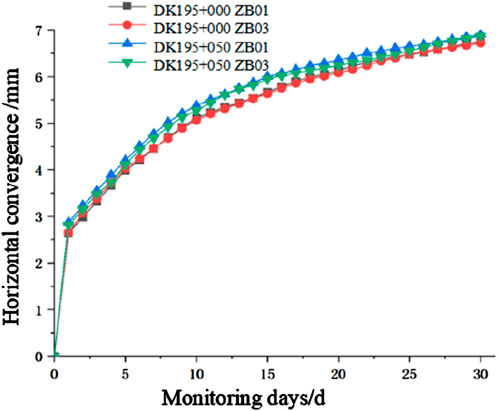
Figure 16. Horizontal displacement curves.
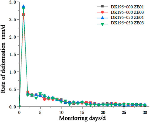
Figure 17. Horizontal displacement rate curves.
As depicted in Figure 16, during the initial excavation stage (0–3 days), the horizontal displacement increases sharply, maintaining a steady rise during 3–20 days. After day 30, the displacement stabilizes. Furthermore, Figures 13, 14, 16 indicate that the horizontal displacement in the shallow soft-plastic loess tunnel is lower than the vault settlement.
As illustrated in Figure 17, during the initial phase of excavation, both sections exhibit a relatively high convergence rate. During the early monitoring period (1–5 days), the deformation rate is approximately 0.5 mm/d. During the middle monitoring period (6–10 days), the convergence rate drops to around 0.3 mm/d. From days 11–20, this rate further decreases to about 0.1 mm/d. During the later monitoring period (21–30 days), the convergence rate stabilizes at nearly zero.
4 Conclusion
This study analyzes the deformation characteristics of the surrounding rock during the construction of a tunnel passing through the soft-plastic layers with different spatial distributions and layer thicknesses through numerical simulations and on-site monitoring. The following conclusions are drawn:
(1) A comparison of the displacement of surrounding rock in areas with different spatial distributions and thicknesses of soft-plastic loess layers reveals that the presence of soft-plastic loess increases the displacement of the surrounding rock. Notably, the distribution of soft-plastic loess exerts a more pronounced influence than its thickness. The most substantial impact is observed when the soft-plastic loess is located above the tunnel vault with a thickness of 5 m.
(2) Numerical analysis, corroborated by on-site monitoring, indicates that the advanced pipe roof support is an effective deformation control technology during the construction of tunnels covered by soft-plastic loess layers.
(3) The deformation characteristic curves of the surrounding rock and the on-site monitoring curves confirm that the deformation process occurs in three distinct stages: rapid deformation at the beginning of excavation, slow deformation following the closure of the primary support, and stable deformation after the construction of the secondary lining. Therefore, the early excavation stage represents a critical period for deformation control. While implementing advanced support measures, it is essential to enhance monitoring efforts.
Data availability statement
The data used to support the findings of this study are available from the corresponding author upon request.
Author contributions
YY: Methodology, Writing – original draft. LL: Writing – original draft, Data curation, Investigation, Writing – review and editing. YL: Writing – original draft, Data curation. HZ: Project administration, Writing – original draft. CG: Writing – original draft, Project administration.
Funding
The author(s) declare that financial support was received for the research and/or publication of this article. This research were supported by grants from Science and Technology Research and Development Plan of China Railway Corporation (Grant No. P2018G048), Science and Technology Research Project of Higher Education Institutions in Hebei Province (Grant No. QN2021219). The funders were not involved in the study design, collection, analysis, interpretation of data, the writing of this article, or the decision to submit it for publication.
Conflict of interest
Author YY was employed by The 4th Engineering Company of China Railway 12th Bureau Group Ltd., Co.
The remaining authors declare that the research was conducted in the absence of any commercial or financial relationships that could be construed as a potential conflict of interest.
Generative AI statement
The author(s) declare that no Generative AI was used in the creation of this manuscript.
Publisher’s note
All claims expressed in this article are solely those of the authors and do not necessarily represent those of their affiliated organizations, or those of the publisher, the editors and the reviewers. Any product that may be evaluated in this article, or claim that may be made by its manufacturer, is not guaranteed or endorsed by the publisher.
References
Anna, J., Peng, L., and Song, H. T. (2011). Shallow depth of the tunnel excavation response research based on CRD method. Procedia Eng. 15, 4852–4856. doi:10.1016/j.proeng.2011.08.905
Cai, H., Hong, R., Xu, L., Wang, C., and Rong, C. (2022). Frost heave and thawing settlement of the ground after using a freeze-sealing pipe-roof method in the construction of the Gongbei Tunnel. Tunn. Undergr. Space Technol. 125 (2), 104503. doi:10.1016/j.tust.2022.104503
Cao, H. J., Liu, Z. Q., and Wu, J. (2018). Study on construction deformation law and reserved deformation of railway loess tunnel. Railw. Stand. Des. 62 (03), 85–89. doi:10.13238/j.issn.1004-2954.201705010001
Chen, G. Y., Liu, B., Wan, M. F., Hao, Z., and Li, W. (2005). Analysis of stress monitoring of a large span highway tunnel in Zhangjialing mountain. Chin. J. Rock Mech. Eng. 2005 (S2), 5509–5515.
Chen, L. J., Ma, P. H., Zhao, J. Y., Xie, F., Yan, R., Leng, Y., et al. (2022). Effect of fracture distribution on the triaxial shear behavior of loess. Front. Earth Sci. 10, 103389. doi:10.3389/feart.2022.1087286
Cheng, X. S., and Wang, J. H. (2013). Construction methods for loss tunnels with super large cross section based on placement control of surrounding rock. Chin. J. Geotechnical Eng. 35 (S1), 82–89.
Gong, B., Jiang, Y. J., and Chen, L. J. (2019). Feasibility investigation of the mechanical behavior of methane hydrate-bearing specimens using the multiple failure method. J. Nat. Gas Sci. Eng. 69, 102915. doi:10.1016/j.jngse.2019.102915
Gong, B., Jiang, Y. J., Yan, P., and Zhang, S. (2020). Discrete element numerical simulation of mechanical properties of methane hydrate-bearing specimen considering deposit angles. J. Nat. Gas Sci. Eng. 76, 103182. doi:10.1016/j.jngse.2020.103182
Hu, S. M., Zhang, D. L., Guo, T., and Yang, X. R. (2012). Analysis on deformation characteristics of large section loss tunnel. J. China Railw. Soc. 34 (8), 117–122. doi:10.3969/j.issn.1001-8360.2012.08.018
Li, J., Tan, Z. S., and Yu, Y. (2011). Research on construction procedure for small large-span tunnel undercrossing highway. Rock Soil Mech. 32 (9), 2803–2809.
Li, J., Zhao, S., Wang, X., Hao, J., Zhi, B., Zhang, H., and Deng, B. (2021). Experimental study on consolidation characteristics of compacted loess. Adv. Civ. Eng. 2021 (5), 1–12. doi:10.1155/2021/6687858
Li, L., Shang, C., Chu, K., Zhou, Z., Song, S., Liu, Z., et al. (2021). Large scale geo mechanical model tests for stability assessment of super large cross section tunnel. Tunn. Undergr. Space Technol. 109, 103756. doi:10.1016/j.tust.2020.103756
Li, P., Xie, W. L., Pak, R., and Vanapalli, S. K. (2018). Microstructural evolution of loess soils from the loess plateau of China. Catena 173, 276–288. doi:10.1016/j.catena.2018.10.006
Liang, X. Y., Hu, S. M., and Zhang, C. H. (2013). Failure modes of surrounding rock of deep buried large section loss tunnel. Chin. J. Geotechnical Eng. 35 (S2), 559–563.
Lin, Zh., Pan, Y. G., Chen, Z. K., Chen, P. F., Xue, B. B., Wang, T. X., et al. (2022). The effect of CRD method and auxiliary construction on surface settlement in shallow-buried tunnels. Front. Earth Sci. 10, 998717. doi:10.3389/feart.2022.998717
Nakajima, S., Sanagawa, T., Matsumaru, T., and Koda, M. (2021). Recent research development and their applications on aseismic reinforcement of existing railway Earth structures. Soils Found. 62 (1), 101104. doi:10.1016/j.sandf.2021.101104
Qin, Y. W., Chen, Y. H., Lai, J. X., Qiu, J., Wang, Z., Liu, T., et al. (2024). Failures in loess slope-tunnel system: an overview of trigging sources, acting mechanism and mitigation strategies. Eng. Fail. Anal. 158, 107996. doi:10.1016/j.engfailanal.2024.107996
Qiu, M. M., Yang, G. L., and Zhang, P. R. (2021). Field test on the construction deformation characteristics for a low highway tunnel at the shallow portal section. Hydrogeology&Engineering Geol. 48 (3), 135–143. doi:10.16030/j.cnki.issn.1000-3665.202008002
Tan, Z. S., Yu, Y., Wang, M. N., and Wang, M. S. (2009). Comparative tests on section steel and steel grid for loss tunnels with large section. Chin. J. Geotechnical Eng. 31 (4), 628–633.
Tu, H. L., Zhou, H., Qiao, C. S., and Gao, Y. (2020). Excavation and kinematic analysis of a shallow large-span tunnel in an up soft/low hard rock stratum. Tunn. Undergr. space Technol. 97 (8), 103245. doi:10.1016/j.tust.2019.103245
Wang, C., and Tannant, D. D. (2004). Rock fracture around a highly stressed tunnel and the impact of a thin tunnel liner for ground control. Int. J. Rock Mechanics&Mining Sci. 41 (3), 490–502. doi:10.1016/j.ijrmms.2003.12.025
Wang, H. F. (2011). The construction technology management point of loss tunnel. Shanxi Science&Technology Commun. (6), 49–51.
Wang, X. D. (2012). Discussion on safety and swift construction of shallow buried large section loss tunnel Railway. Constr. Technol. (5), 86–90.
Wu, K., Yu, Y. L., Cui, S. S., and Zhang, Q. (2018). Construction mechanical mechanism of shallow subway tunnel Group with large span variable cross section. Tech. Geol. Eng. 36, 3879–3891. doi:10.1007/s10706-018-0579-7
Zhang, X. (2020). Research on mechanical characteristics of support structure in loess tunnel with large cross-section. Beijing: Beijing Jiaotong University.
Keywords: soft-plastic loess, loess tunnel, deformation, surrounding rock, pipe roof, support
Citation: Yang Y, Liu L, Liu Y, Zhang H and Guo C (2025) Deformation of surrounding rock in a shallow large-section tunnel passing through soft-plastic loess layer. Front. Earth Sci. 13:1605205. doi: 10.3389/feart.2025.1605205
Received: 03 April 2025; Accepted: 10 June 2025;
Published: 01 July 2025.
Edited by:
Binbin Yang, Xuchang University, ChinaCopyright © 2025 Yang, Liu, Liu, Zhang and Guo. This is an open-access article distributed under the terms of the Creative Commons Attribution License (CC BY). The use, distribution or reproduction in other forums is permitted, provided the original author(s) and the copyright owner(s) are credited and that the original publication in this journal is cited, in accordance with accepted academic practice. No use, distribution or reproduction is permitted which does not comply with these terms.
*Correspondence: Liu Liu, TGl1bGl1QGhlanR4eS5lZHUuY24=